sensor FORD F250 2013 User Guide
[x] Cancel search | Manufacturer: FORD, Model Year: 2013, Model line: F250, Model: FORD F250 2013Pages: 577, PDF Size: 7.74 MB
Page 181 of 577
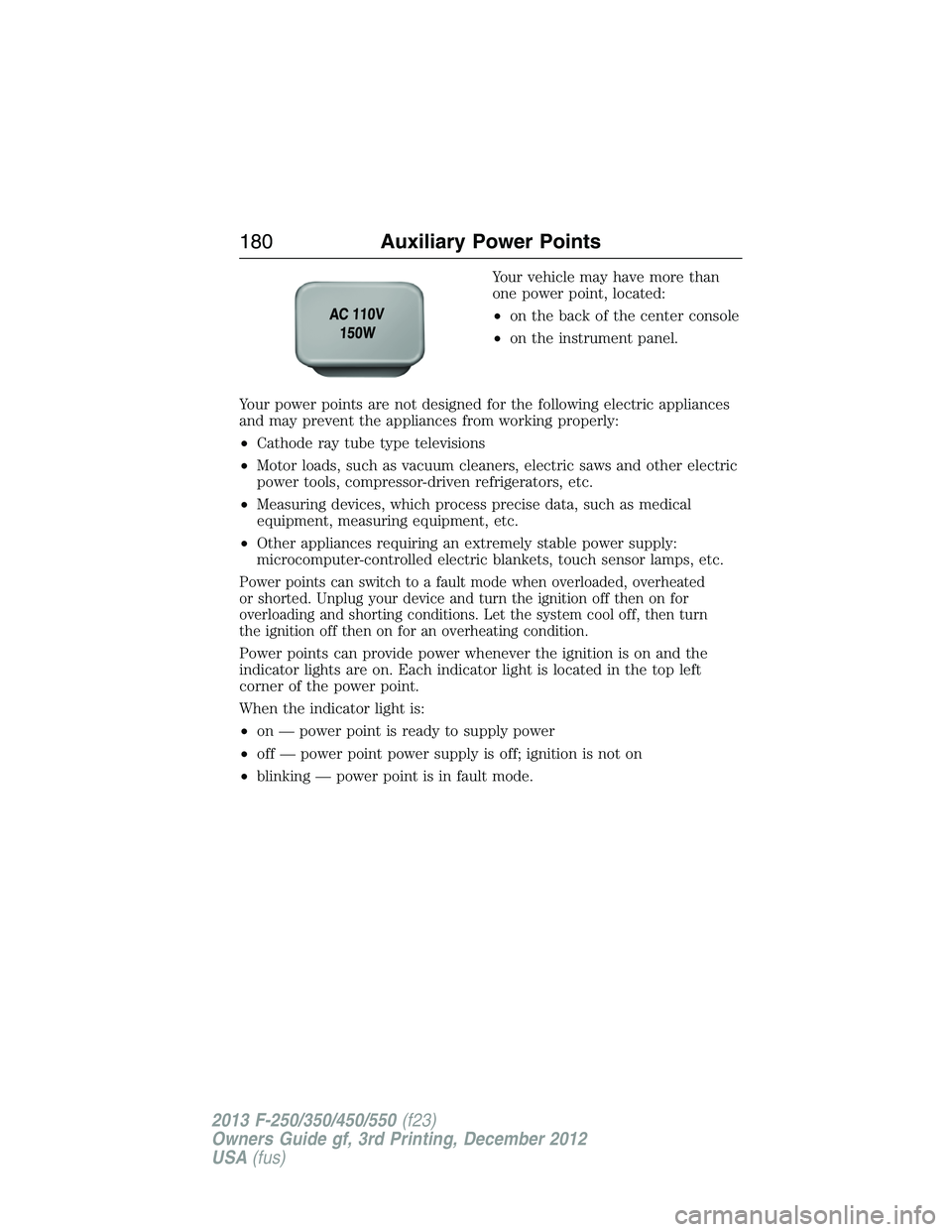
Your vehicle may have more than
one power point, located:
•on the back of the center console
•on the instrument panel.
Your power points are not designed for the following electric appliances
and may prevent the appliances from working properly:
•Cathode ray tube type televisions
•Motor loads, such as vacuum cleaners, electric saws and other electric
power tools, compressor-driven refrigerators, etc.
•Measuring devices, which process precise data, such as medical
equipment, measuring equipment, etc.
•Other appliances requiring an extremely stable power supply:
microcomputer-controlled electric blankets, touch sensor lamps, etc.
Power points can switch to a fault mode when overloaded, overheated
or shorted. Unplug your device and turn the ignition off then on for
overloading and shorting conditions. Let the system cool off, then turn
the ignition off then on for an overheating condition.
Power points can provide power whenever the ignition is on and the
indicator lights are on. Each indicator light is located in the top left
corner of the power point.
When the indicator light is:
•on — power point is ready to supply power
•off — power point power supply is off; ignition is not on
•blinking — power point is in fault mode.
180Auxiliary Power Points
2013 F-250/350/450/550(f23)
Owners Guide gf, 3rd Printing, December 2012
USA(fus)
Page 209 of 577
HILL START ASSIST
WARNING:The hill start assist feature does not replace the
parking brake. When you leave the vehicle, always apply the
parking brake and shift the transmission into P (Park).
WARNING:You must remain in the vehicle once you have
activated the hill start assist feature.
WARNING:During all times, you are responsible for controlling
the vehicle, supervising the hill start assist system and
intervening, if required.
WARNING:If the engine is revved excessively, or if a
malfunction is detected when the hill start assist feature is
active, the hill start assist feature will be deactivated.
Hill start assist keeps your vehicle stationary long enough to move your
foot from the brake pedal to the accelerator pedal when your vehicle is
on a slope.
The brakes are released automatically once the engine has developed
sufficient drive to prevent the vehicle from rolling down the slope. This
is an advantage when pulling away on a slope, (for example from a car
park ramp, traffic lights or when reversing uphill into a parking space).
Using Hill Start Assist
1. Press the brake pedal to bring the vehicle to a complete standstill.
Keep the brake pedal pressed.
2. If the sensors detect that the vehicle is on a slope, the hill start assist
feature will be activated automatically.
3. When you remove your foot from the brake pedal, the vehicle will
remain on the slope without rolling away for approximately two or three
seconds. This hold time will automatically be extended if you are in the
process of driving off.
4. Drive off in the normal manner. The brakes will be released
automatically.
208Transmission
2013 F-250/350/450/550(f23)
Owners Guide gf, 3rd Printing, December 2012
USA(fus)
Page 228 of 577

PRINCIPLES OF OPERATION
WARNING:Vehicle modifications involving braking system,
aftermarket roof racks, suspension, steering system, tire
construction or wheel and tire size may change the handling
characteristics of the vehicle and may adversely affect the performance
of the AdvanceTrac® system. In addition, installing any stereo
loudspeakers may interfere with and adversely affect the AdvanceTrac®
system. Install any aftermarket stereo loudspeaker as far as possible
from the front center console, the tunnel, and the front seats in order
to minimize the risk of interfering with the AdvanceTrac® sensors.
Reducing the effectiveness of the AdvanceTrac® system could lead to
an increased risk of loss of vehicle control, vehicle rollover, personal
injury and death.
WARNING:Remember that even advanced technology cannot
defy the laws of physics. It’s always possible to lose control of a
vehicle due to inappropriate driver input for the conditions. Aggressive
driving on any road condition can cause you to lose control of your
vehicle increasing the risk of personal injury or property damage.
Activation of the AdvanceTrac® system is an indication that at least
some of the tires have exceeded their ability to grip the road; this could
reduce the operator’s ability to control the vehicle potentially resulting
in a loss of vehicle control, vehicle rollover, personal injury and death.
If your AdvanceTrac® system activates, SLOW DOWN.
Stability Control227
2013 F-250/350/450/550(f23)
Owners Guide gf, 3rd Printing, December 2012
USA(fus)
Page 233 of 577
SENSING SYSTEM (IF EQUIPPED)
WARNING:To help avoid personal injury, please read and
understand the limitations of the system as contained in this
section. Sensing is only an aid for some (generally large and fixed)
objects when moving in reverse on a flat surface at parking speeds.
Traffic control systems, inclement weather, air brakes, and external
motors and fans may also affect the function of the sensing system;
this may include reduced performance or a false activation.
WARNING:To help avoid personal injury, always use caution
when in R (Reverse) and when using the sensing system.
WARNING:This system is not designed to prevent contact with
small or moving objects. The system is designed to provide a
warning to assist the driver in detecting large stationary objects to
avoid damaging the vehicle. The system may not detect smaller objects,
particularly those close to the ground.
WARNING:Certain add-on devices such as large trailer hitches,
bike or surfboard racks and any device that may block the normal
detection zone of the system, may create false beeps.
Note:Keep the sensors (located on the bumper/fascia) free from snow,
ice and large accumulations of dirt. If the sensors are covered, the
system’s accuracy can be affected. Do not clean the sensors with sharp
objects.
Note:If your vehicle sustains damage to the bumper/fascia, leaving it
misaligned or bent, the sensing zone may be altered causing inaccurate
measurement of obstacles or false alarms.
Note:If your vehicle is equipped with MyKey®, it is possible to prevent
turning the sensing system off. Refer to theMyKey®chapter.
Note:If your vehicle is equipped with a fully integrated electronic
trailer brake controller (TBC) and a trailer with electric trailer brakes is
connected to your vehicle, the RSS will be disabled. When the vehicle is
shifted into reverse, the message center display will remain in the Rear
Park Aid Off selection. For more information on the TBC, refer to the
Towingchapter.
232Parking Aids
2013 F-250/350/450/550(f23)
Owners Guide gf, 3rd Printing, December 2012
USA(fus)
Page 234 of 577
The sensing system warns the driver of obstacles within a certain range
of the bumper area. The system turns on automatically whenever the
ignition is switched on.
When receiving a detection warning, the radio volume is reduced to a
predetermined level. After the warning goes away, the radio volume
returns to the previous level.
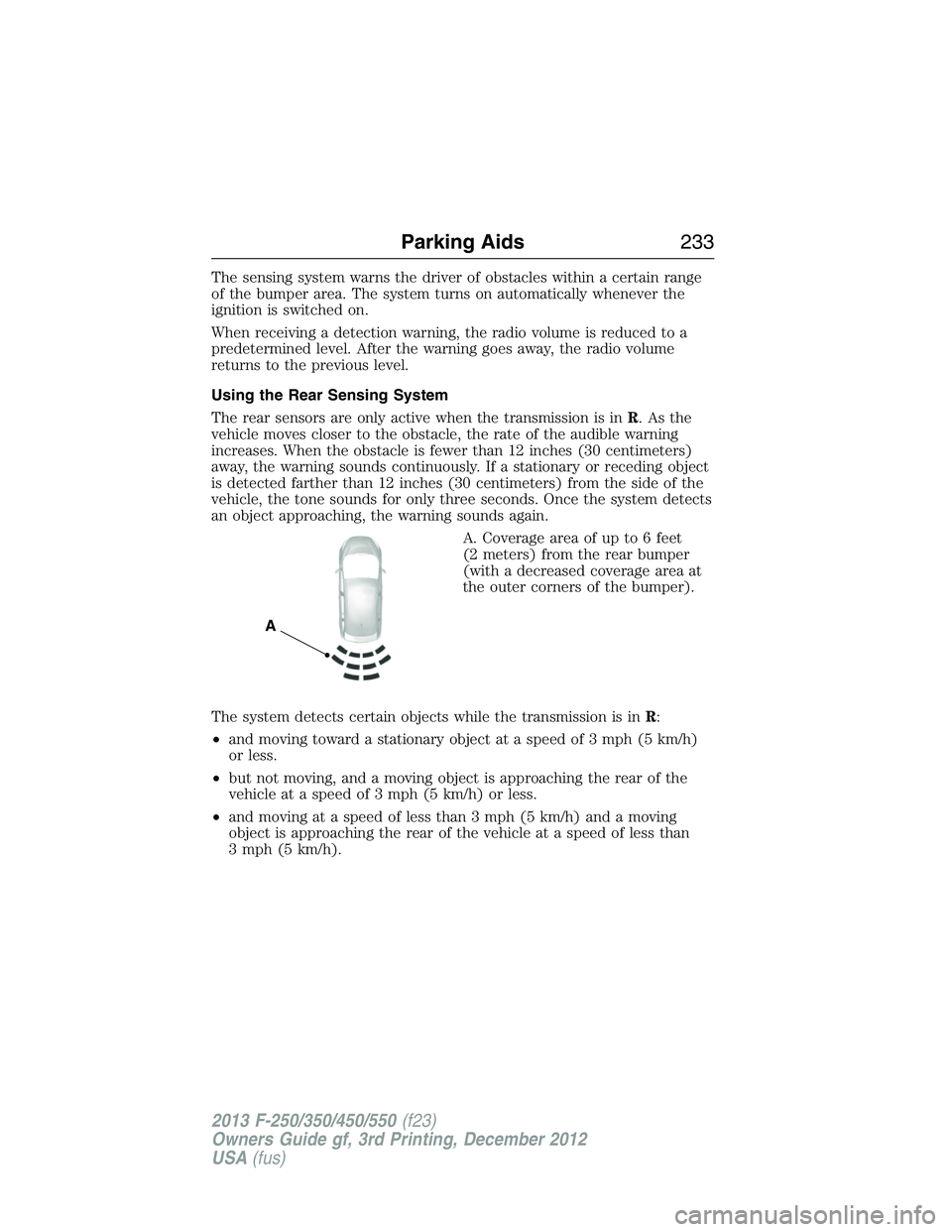
Using the Rear Sensing System
The rear sensors are only active when the transmission is inR.Asthe
vehicle moves closer to the obstacle, the rate of the audible warning
increases. When the obstacle is fewer than 12 inches (30 centimeters)
away, the warning sounds continuously. If a stationary or receding object
is detected farther than 12 inches (30 centimeters) from the side of the
vehicle, the tone sounds for only three seconds. Once the system detects
an object approaching, the warning sounds again.
A. Coverage area of up to 6 feet
(2 meters) from the rear bumper
(with a decreased coverage area at
the outer corners of the bumper).
The system detects certain objects while the transmission is inR:
•and moving toward a stationary object at a speed of 3 mph (5 km/h)
or less.
•but not moving, and a moving object is approaching the rear of the
vehicle at a speed of 3 mph (5 km/h) or less.
•and moving at a speed of less than 3 mph (5 km/h) and a moving
object is approaching the rear of the vehicle at a speed of less than
3 mph (5 km/h).
A
Parking Aids233
2013 F-250/350/450/550(f23)
Owners Guide gf, 3rd Printing, December 2012
USA(fus)
Page 275 of 577
Snowplowing with your Air Bag Equipped Vehicle
WARNING:Do not attempt to service, repair, or modify the air
bag supplemental restraint system (SRS) or its fuses. See your
Ford or Lincoln Mercury dealer.
WARNING:Additional equipment such as snowplow equipment
may effect the performance of the air bag sensors increasing the
risk of injury. Please refer to theBody Builders Layout Bookfor
instructions about the appropriate installation of additional equipment.
WARNING:All occupants of the vehicle, including the driver,
should always properly wear their safety belts, even when an air
bag supplemental restraint system (SRS) is provided.
Your vehicle is equipped with a driver and passenger air bag
supplemental restraint system. The supplemental restrain system is
designed to activate in certain frontal and offset frontal collisions when
the vehicle sustains sufficient longitudinal deceleration.
Careless or high speed driving while plowing snow which results in
sufficient vehicle decelerations can deploy the air bag. Such driving also
increases the risk of accidents.
Never remove or defeat the tripping mechanisms designed into the snow
removal equipment by its manufacturer. Doing so may cause damage to
the vehicle and the snow removal equipment as well as possible air bag
deployment.
274Driving Hints
2013 F-250/350/450/550(f23)
Owners Guide gf, 3rd Printing, December 2012
USA(fus)
Page 324 of 577
AIR FILTER CHECK
Refer toScheduled Maintenance Informationfor the appropriate
intervals for changing the air filter element.
When changing the air filter element, use only the Motorcraft® air filter
element listed. Refer to theMotorcraft® Part Numbers.
The following procedure is for vehicles equipped with a gasoline engine.
If your vehicle is equipped with a diesel engine, refer to the diesel
supplement.
Note:Do not start your engine with the air cleaner removed and do not
remove it while the engine is running.
Note:Failure to use the correct air filter element may result in severe
engine damage. The customer warranty may be void for any damage to
the engine if the correct air filter element is not used.
Changing the Air Filter Element
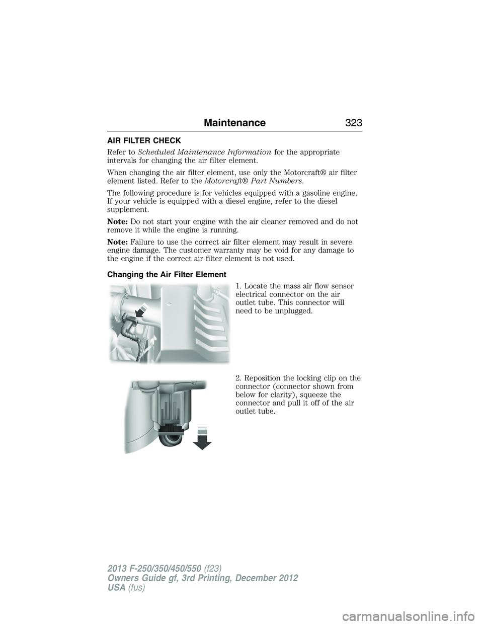
1. Locate the mass air flow sensor
electrical connector on the air
outlet tube. This connector will
need to be unplugged.
2. Reposition the locking clip on the
connector (connector shown from
below for clarity), squeeze the
connector and pull it off of the air
outlet tube.
Maintenance323
2013 F-250/350/450/550(f23)
Owners Guide gf, 3rd Printing, December 2012
USA(fus)
Page 326 of 577
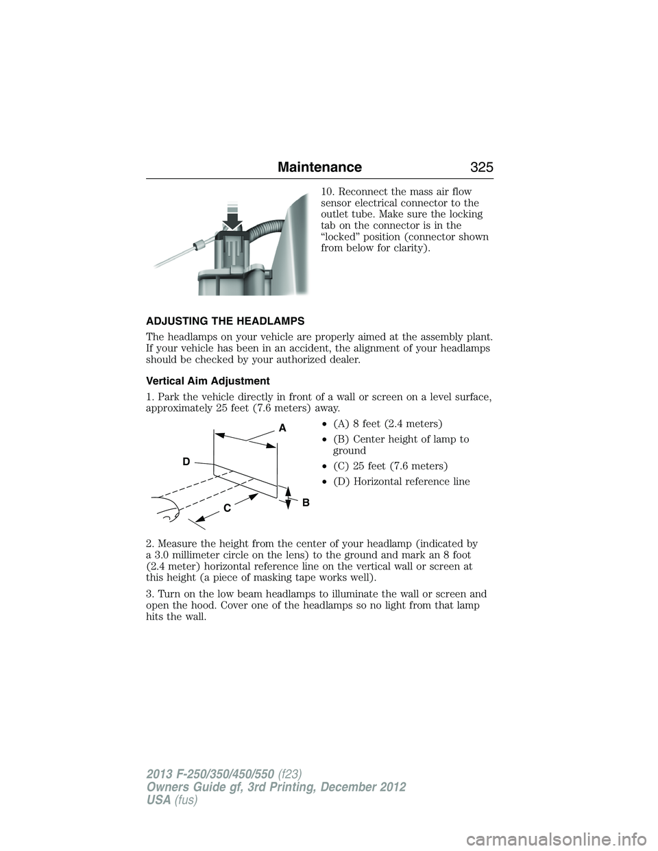
10. Reconnect the mass air flow
sensor electrical connector to the
outlet tube. Make sure the locking
tab on the connector is in the
“locked” position (connector shown
from below for clarity).
ADJUSTING THE HEADLAMPS
The headlamps on your vehicle are properly aimed at the assembly plant.
If your vehicle has been in an accident, the alignment of your headlamps
should be checked by your authorized dealer.
Vertical Aim Adjustment
1. Park the vehicle directly in front of a wall or screen on a level surface,
approximately 25 feet (7.6 meters) away.
•(A) 8 feet (2.4 meters)
•(B) Center height of lamp to
ground
•(C) 25 feet (7.6 meters)
•(D) Horizontal reference line
2. Measure the height from the center of your headlamp (indicated by
a 3.0 millimeter circle on the lens) to the ground and mark an 8 foot
(2.4 meter) horizontal reference line on the vertical wall or screen at
this height (a piece of masking tape works well).
3. Turn on the low beam headlamps to illuminate the wall or screen and
open the hood. Cover one of the headlamps so no light from that lamp
hits the wall.
C
A
B
D
Maintenance325
2013 F-250/350/450/550(f23)
Owners Guide gf, 3rd Printing, December 2012
USA(fus)
Page 361 of 577
WARNING:To reduce the risk of serious injury, when mounting
replacement tires and wheels, you should not exceed the
maximum pressure indicated on the sidewall of the tire to set the beads
without additional precautions listed below. If the beads do not seat at
the maximum pressure indicated, re-lubricate and try again.
When inflating the tire for mounting pressures up to 20 psi (138 kPa)
greater than the maximum pressure on the tire sidewall, take the
following precautions to protect the person mounting the tire:
1. Make sure that you have the correct tire and wheel size.
2. Lubricate the tire bead and wheel bead seat area again.
3. Stand at a minimum of 12 feet (3.66 meters) away from the tire
wheel assembly.
4. Use both eye and ear protection.
For a mounting pressure more than 20 psi (138 kPa) greater than
the maximum pressure, an authorized dealer or other tire service
professional should do the mounting.
Always inflate steel carcass tires with a remote air fill with the person
inflating standing at a minimum of 12 feet (3.66 meters) away from the
tire wheel assembly.
Your vehicle is equipped with tires designed to provide a safe ride and
handling capability.
Important:Remember to replace the wheel valve stems when the road
tires are replaced on your vehicle.
The two front tires or two rear tires should generally be replaced as a pair.
The tire pressure sensors mounted in the wheels are not designed to be
used in aftermarket wheels.
The use of wheels or tires not recommended by Ford Motor Company
may affect the operation of your tire pressure monitoring system
(if equipped).
If the tire pressure monitoring system indicator is flashing, the system is
malfunctioning. Your replacement tire might be incompatible with your
tire pressure monitoring system, or some component of the system may
be damaged(if equipped).
Safety Practices
WARNING:If your vehicle is stuck in snow, mud, or sand, do not
rapidly spin the tires. Spinning the tires can tear the tire and cause
an explosion. A tire can explode in as little as three to five seconds.
360Wheels and Tires
2013 F-250/350/450/550(f23)
Owners Guide gf, 3rd Printing, December 2012
USA(fus)
Page 363 of 577
Tire Rotation
WARNING:If the tire label shows different tire pressures for
the front and rear tires and the vehicle is equipped with a tire
pressure monitoring system, then the settings for the system sensors
need to be updated. Always perform the system reset procedure after
tire rotation. If the system is not reset, it may not provide a low tire
pressure warning when necessary. See the TPMS reset procedure in
this chapter.
Note:If your tires show uneven wear ask an authorized dealer to check
for and correct any wheel misalignment, tire imbalance or mechanical
problem involved before tire rotation.
Note:Your vehicle may be equipped with a dissimilar spare tire and
wheel assembly. A dissimilar spare tire and wheel assembly is defined as
a spare tire or wheel that is different in brand, size or appearance from
the road tires and wheels. If you have a dissimilar spare tire and wheel
assembly, it is intended for temporary use only and should not be used
in a tire rotation.
Note:After having your tires rotated, inflation pressure must be checked
and adjusted to the vehicle requirements.
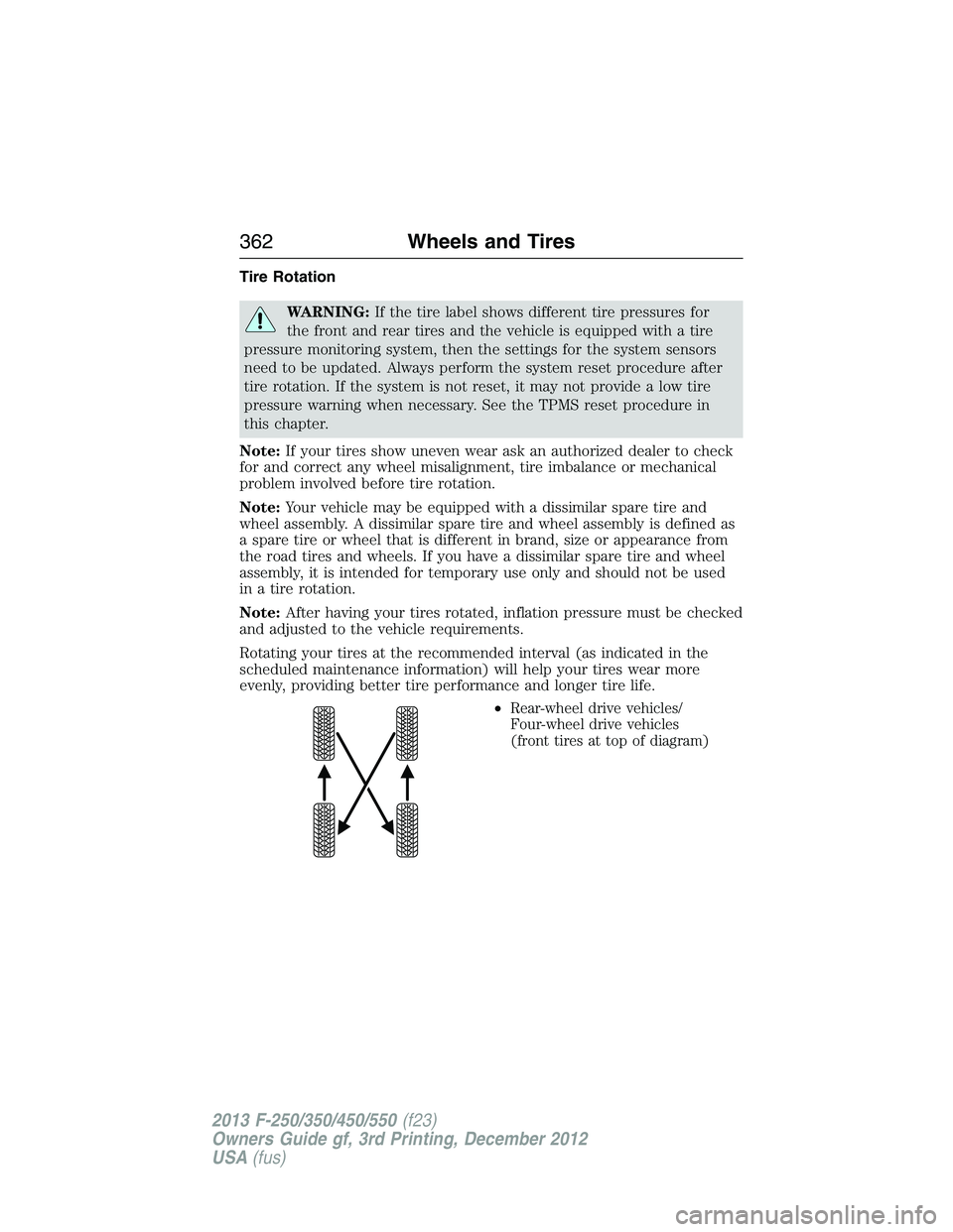
Rotating your tires at the recommended interval (as indicated in the
scheduled maintenance information) will help your tires wear more
evenly, providing better tire performance and longer tire life.
•
Rear-wheel drive vehicles/
Four-wheel drive vehicles
(front tires at top of diagram)
362Wheels and Tires
2013 F-250/350/450/550(f23)
Owners Guide gf, 3rd Printing, December 2012
USA(fus)