FORD F250 2013 Owners Manual
Manufacturer: FORD, Model Year: 2013, Model line: F250, Model: FORD F250 2013Pages: 577, PDF Size: 7.74 MB
Page 381 of 577
The following steps apply to F–350 Dual Rear Wheel, F-450 and F-550
vehicles only:
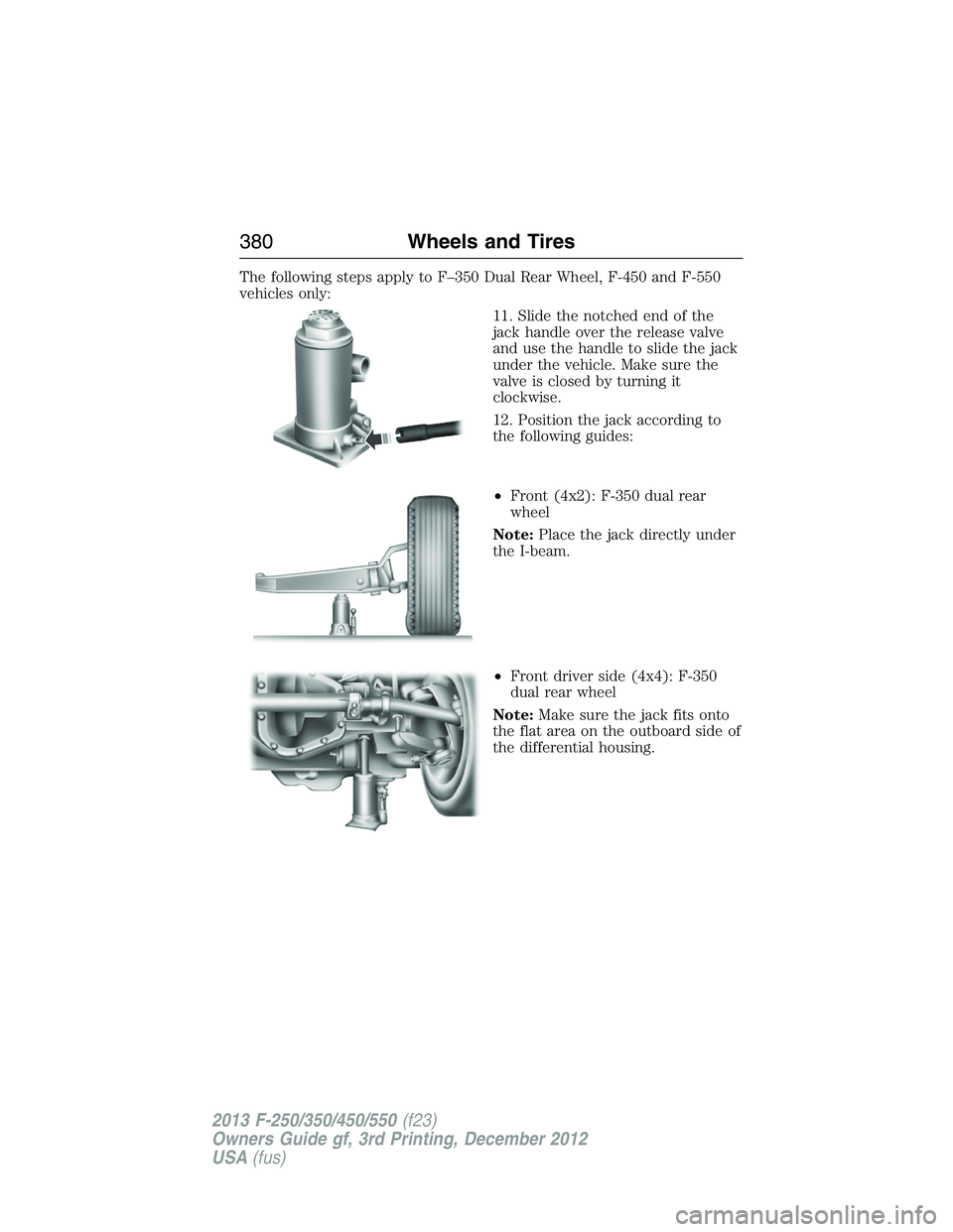
11. Slide the notched end of the
jack handle over the release valve
and use the handle to slide the jack
under the vehicle. Make sure the
valve is closed by turning it
clockwise.
12. Position the jack according to
the following guides:
•Front (4x2): F-350 dual rear
wheel
Note:Place the jack directly under
the I-beam.
•Front driver side (4x4): F-350
dual rear wheel
Note:Make sure the jack fits onto
the flat area on the outboard side of
the differential housing.
380Wheels and Tires
2013 F-250/350/450/550(f23)
Owners Guide gf, 3rd Printing, December 2012
USA(fus)
Page 382 of 577
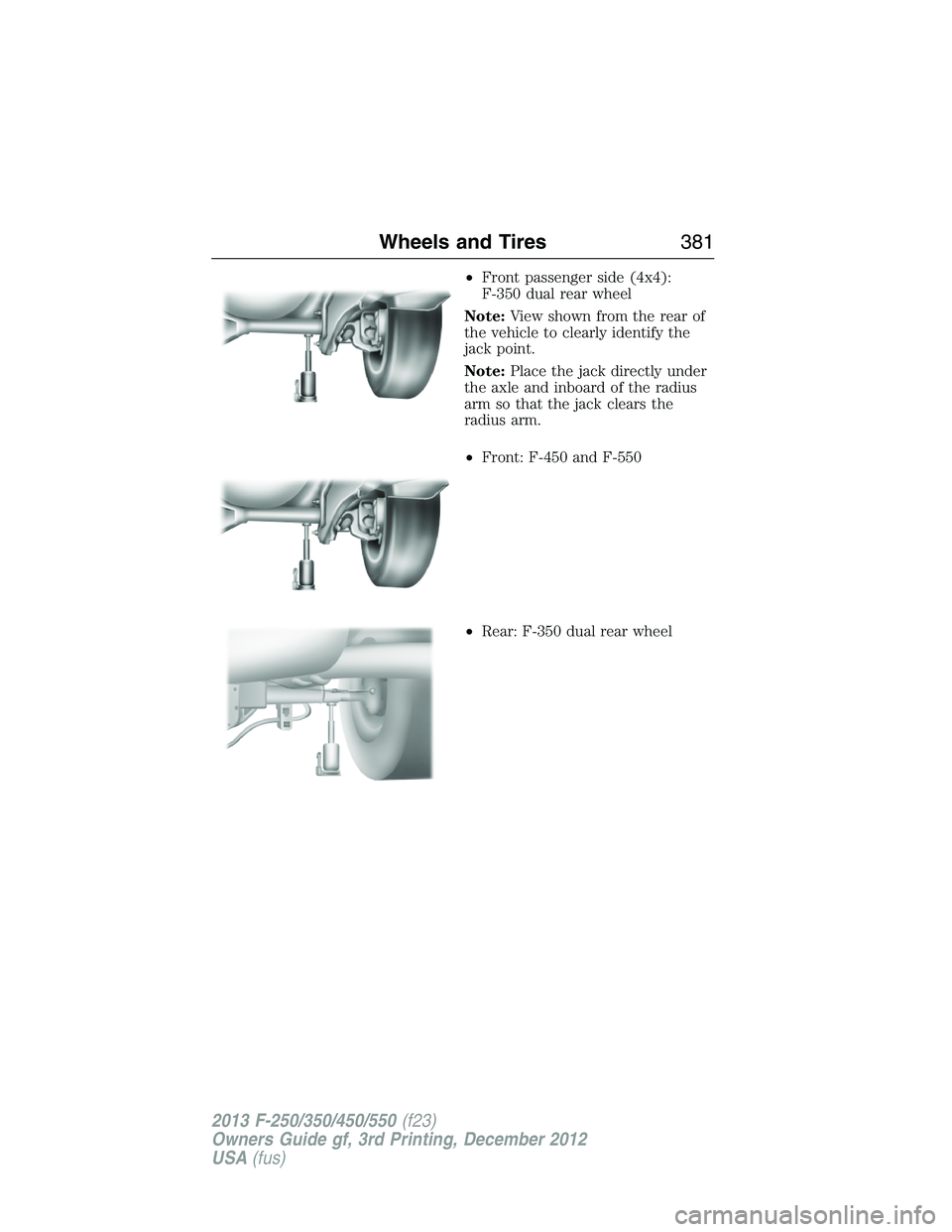
•Front passenger side (4x4):
F-350 dual rear wheel
Note:View shown from the rear of
the vehicle to clearly identify the
jack point.
Note:Place the jack directly under
the axle and inboard of the radius
arm so that the jack clears the
radius arm.
•Front: F-450 and F-550
•Rear: F-350 dual rear wheel
Wheels and Tires381
2013 F-250/350/450/550(f23)
Owners Guide gf, 3rd Printing, December 2012
USA(fus)
Page 383 of 577
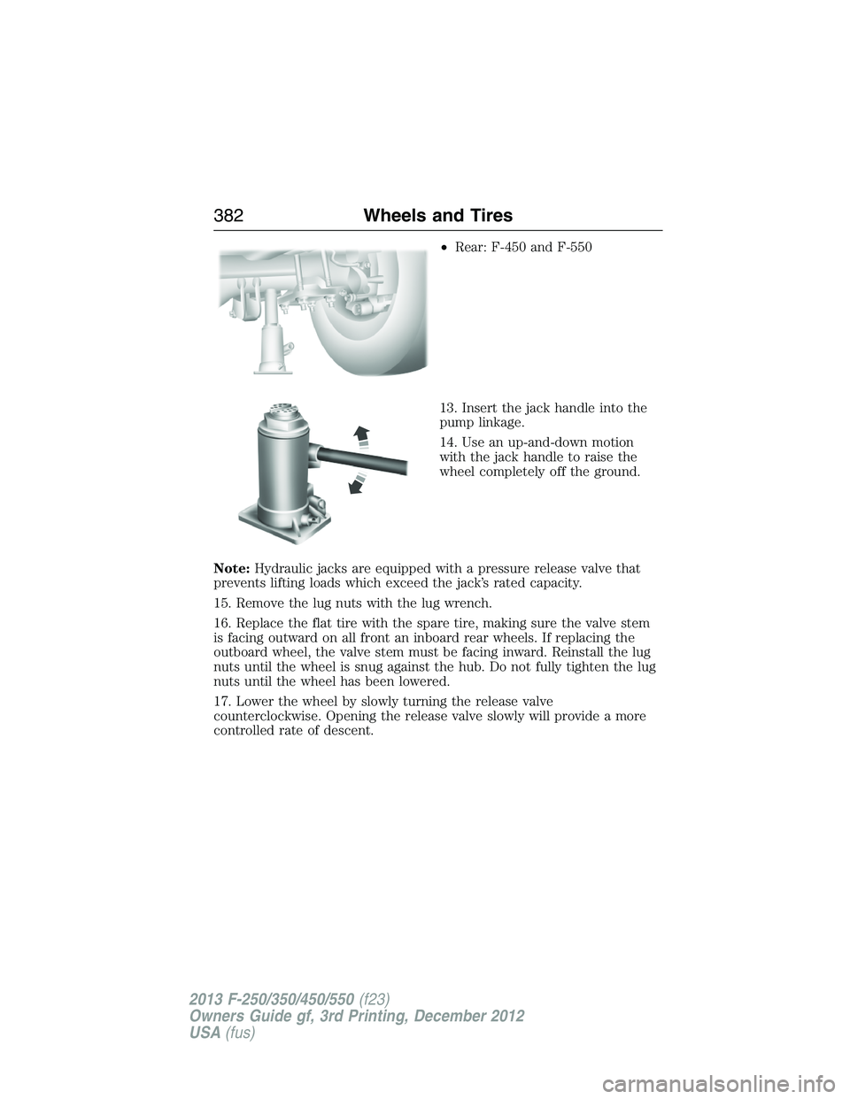
•Rear: F-450 and F-550
13. Insert the jack handle into the
pump linkage.
14. Use an up-and-down motion
with the jack handle to raise the
wheel completely off the ground.
Note:Hydraulic jacks are equipped with a pressure release valve that
prevents lifting loads which exceed the jack’s rated capacity.
15. Remove the lug nuts with the lug wrench.
16. Replace the flat tire with the spare tire, making sure the valve stem
is facing outward on all front an inboard rear wheels. If replacing the
outboard wheel, the valve stem must be facing inward. Reinstall the lug
nuts until the wheel is snug against the hub. Do not fully tighten the lug
nuts until the wheel has been lowered.
17. Lower the wheel by slowly turning the release valve
counterclockwise. Opening the release valve slowly will provide a more
controlled rate of descent.
382Wheels and Tires
2013 F-250/350/450/550(f23)
Owners Guide gf, 3rd Printing, December 2012
USA(fus)
Page 384 of 577
Note:The following steps apply to all vehicles:
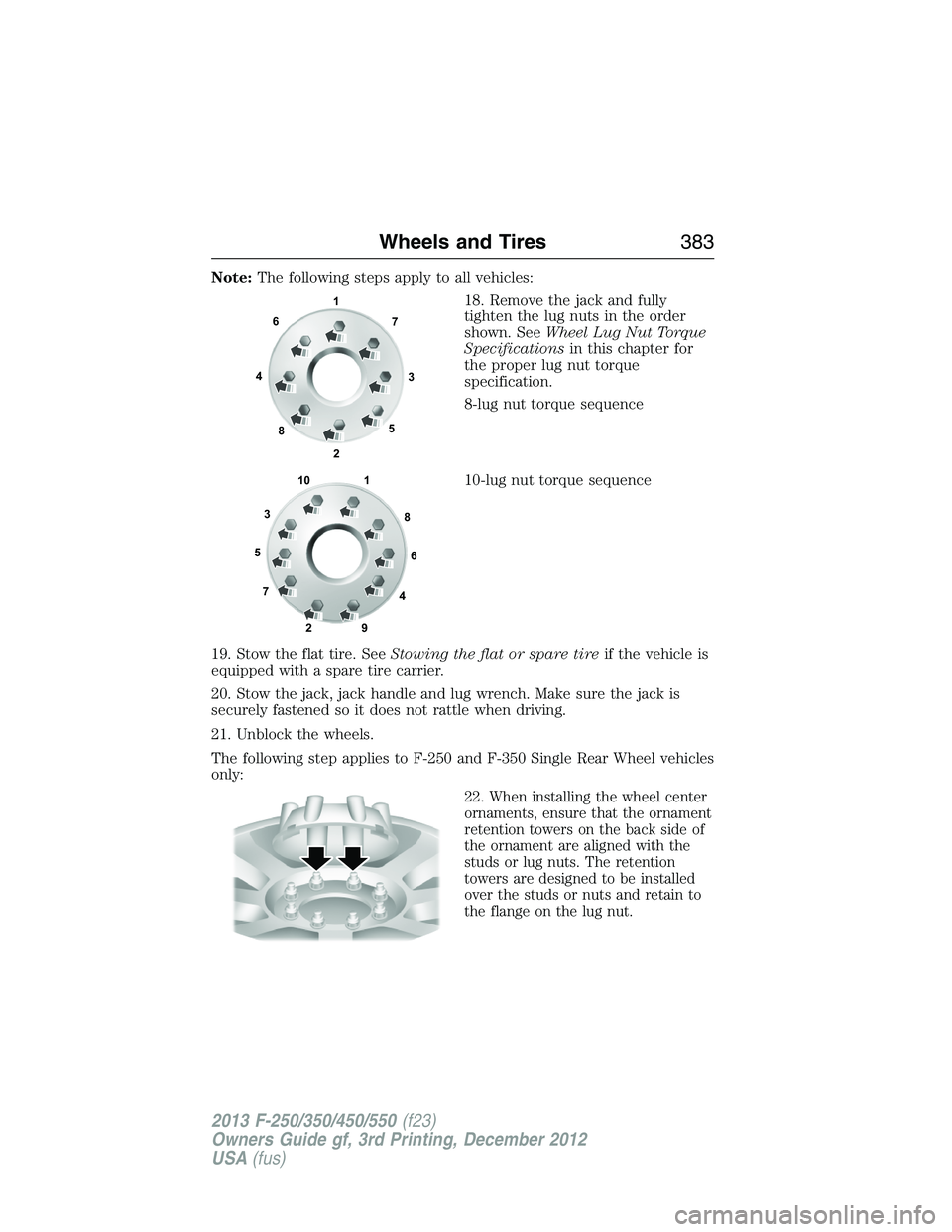
18. Remove the jack and fully
tighten the lug nuts in the order
shown. SeeWheel Lug Nut Torque
Specificationsin this chapter for
the proper lug nut torque
specification.
8-lug nut torque sequence
10-lug nut torque sequence
19. Stow the flat tire. SeeStowing the flat or spare tireif the vehicle is
equipped with a spare tire carrier.
20. Stow the jack, jack handle and lug wrench. Make sure the jack is
securely fastened so it does not rattle when driving.
21. Unblock the wheels.
The following step applies to F-250 and F-350 Single Rear Wheel vehicles
only:
22.
When installing the wheel center
ornaments, ensure that the ornament
retention towers on the back side of
the ornament are aligned with the
studs or lug nuts. The retention
towers are designed to be installed
over the studs or nuts and retain to
the flange on the lug nut.
1
3 4
27 6
5
8
1
2 3
4 5
6
78
9 10
Wheels and Tires383
2013 F-250/350/450/550(f23)
Owners Guide gf, 3rd Printing, December 2012
USA(fus)
Page 385 of 577
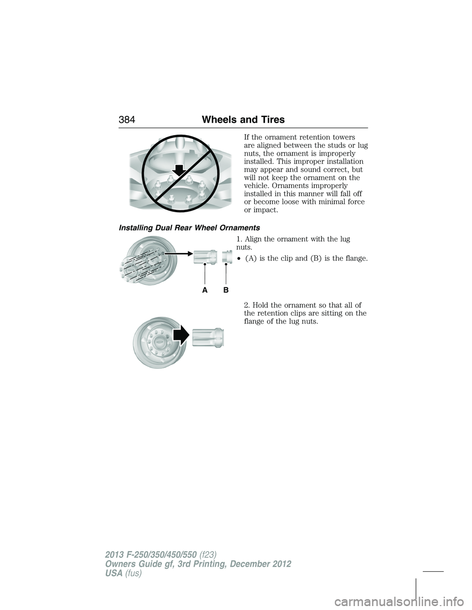
If the ornament retention towers
are aligned between the studs or lug
nuts, the ornament is improperly
installed. This improper installation
may appear and sound correct, but
will not keep the ornament on the
vehicle. Ornaments improperly
installed in this manner will fall off
or become loose with minimal force
or impact.
Installing Dual Rear Wheel Ornaments
1.
Align the ornament with the lug
nuts.
•(A) is the clip and (B) is the flange.
2. Hold the ornament so that all of
the retention clips are sitting on the
flange of the lug nuts.
AB
384Wheels and Tires
2013 F-250/350/450/550(f23)
Owners Guide gf, 3rd Printing, December 2012
USA(fus)
Page 386 of 577
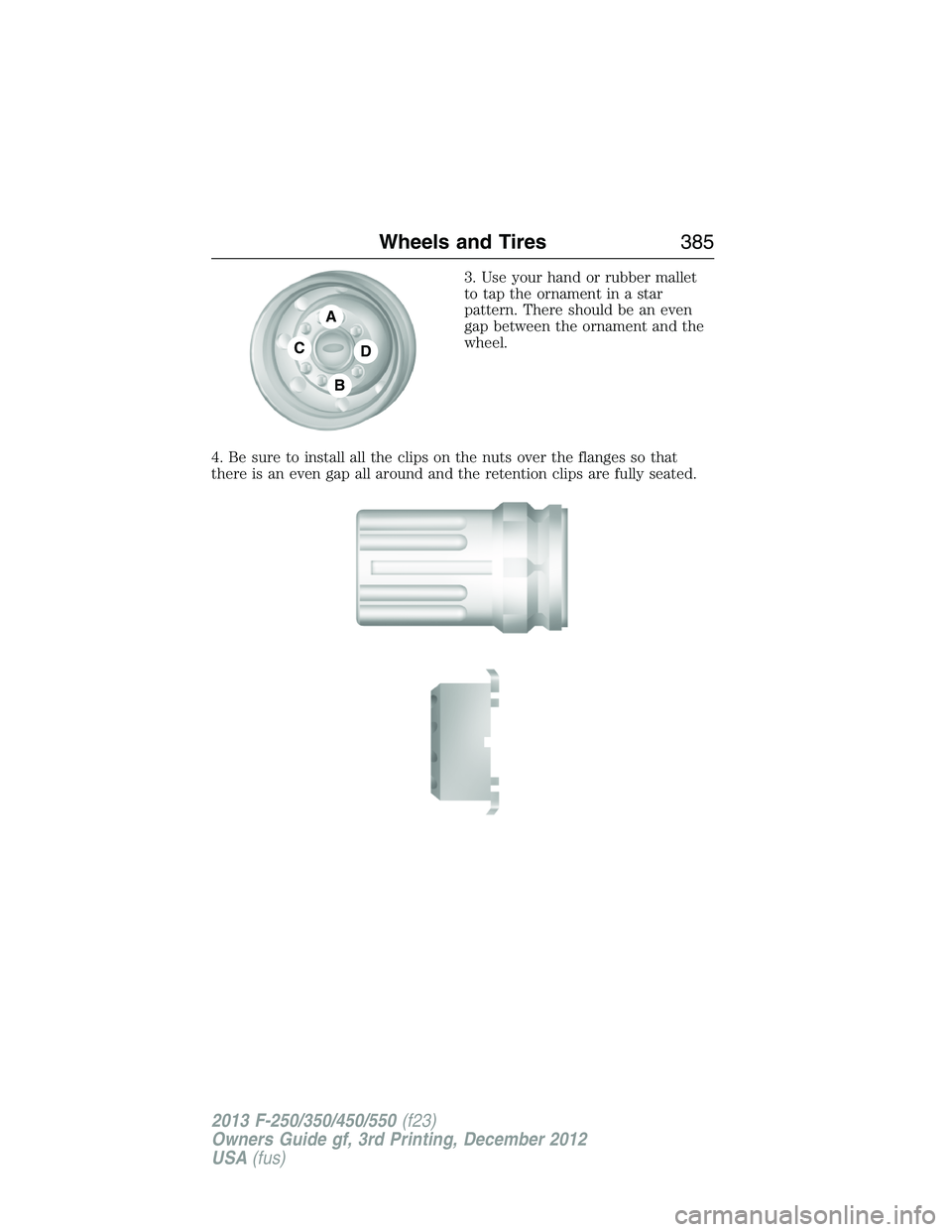
3. Use your hand or rubber mallet
to tap the ornament in a star
pattern. There should be an even
gap between the ornament and the
wheel.
4. Be sure to install all the clips on the nuts over the flanges so that
there is an even gap all around and the retention clips are fully seated.
A
C
B
D
Wheels and Tires385
2013 F-250/350/450/550(f23)
Owners Guide gf, 3rd Printing, December 2012
USA(fus)
Page 387 of 577
Stowing the flat/spare tire
Note:Failure to follow spare tire stowage instructions may result in
failure of cable or loss of spare tire.
Note:
If you are stowing a tire that requires reattaching it to the vehicle
with a tether, perform these steps first, then proceed with the steps
following.
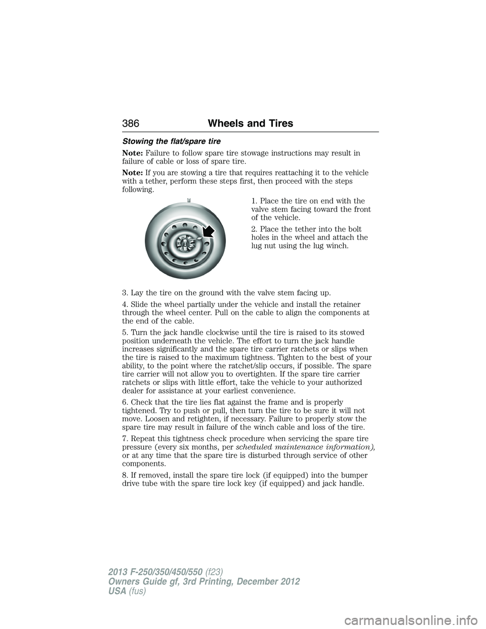
1. Place the tire on end with the
valve stem facing toward the front
of the vehicle.
2. Place the tether into the bolt
holes in the wheel and attach the
lug nut using the lug winch.
3. Lay the tire on the ground with the valve stem facing up.
4. Slide the wheel partially under the vehicle and install the retainer
through the wheel center. Pull on the cable to align the components at
the end of the cable.
5. Turn the jack handle clockwise until the tire is raised to its stowed
position underneath the vehicle. The effort to turn the jack handle
increases significantly and the spare tire carrier ratchets or slips when
the tire is raised to the maximum tightness. Tighten to the best of your
ability, to the point where the ratchet/slip occurs, if possible. The spare
tire carrier will not allow you to overtighten. If the spare tire carrier
ratchets or slips with little effort, take the vehicle to your authorized
dealer for assistance at your earliest convenience.
6. Check that the tire lies flat against the frame and is properly
tightened. Try to push or pull, then turn the tire to be sure it will not
move. Loosen and retighten, if necessary. Failure to properly stow the
spare tire may result in failure of the winch cable and loss of the tire.
7. Repeat this tightness check procedure when servicing the spare tire
pressure (every six months, perscheduled maintenance information),
or at any time that the spare tire is disturbed through service of other
components.
8. If removed, install the spare tire lock (if equipped) into the bumper
drive tube with the spare tire lock key (if equipped) and jack handle.
386Wheels and Tires
2013 F-250/350/450/550(f23)
Owners Guide gf, 3rd Printing, December 2012
USA(fus)
Page 388 of 577
TECHNICAL SPECIFICATIONS
Wheel Lug Nut Torque Specifications
WARNING:When a wheel is installed, always remove any
corrosion, dirt or foreign materials present on the mounting
surfaces of the wheel or the surface of the wheel hub, brake drum or
brake disc that contacts the wheel. Make sure that any fasteners that
attach the rotor to the hub are secured so they do not interfere with
the mounting surfaces of the wheel. Installing wheels without correct
metal-to-metal contact at the wheel mounting surfaces can cause the
wheel nuts to loosen and the wheel to come off while the vehicle is in
motion, resulting in loss of control.
On vehicles equipped with single rear wheels, retighten the lug nuts to
the specified torque at 100 miles (160 kilometers) after any wheel
disturbance (such as tire rotation, changing a flat tire, wheel removal).
On vehicles equipped with dual rear wheels, retighten the wheel lug nuts
to the specified torque at 100 miles (160 kilometers), and again at
500 miles (800 kilometers) of new vehicle operation and after any wheel
disturbance (such as tire rotation, changing a flat tire, wheel removal).
Wheels and Tires387
2013 F-250/350/450/550(f23)
Owners Guide gf, 3rd Printing, December 2012
USA(fus)
Page 389 of 577
Bolt size Wheel lug nut torque*
ft-lb N•m
M14 x 1.5 165 224
* Torque specifications are for nut and bolt threads free of dirt and
rust. Use only Ford recommended replacement fasteners.
It is important to follow the proper wheel mounting and lug nut torque
procedures.
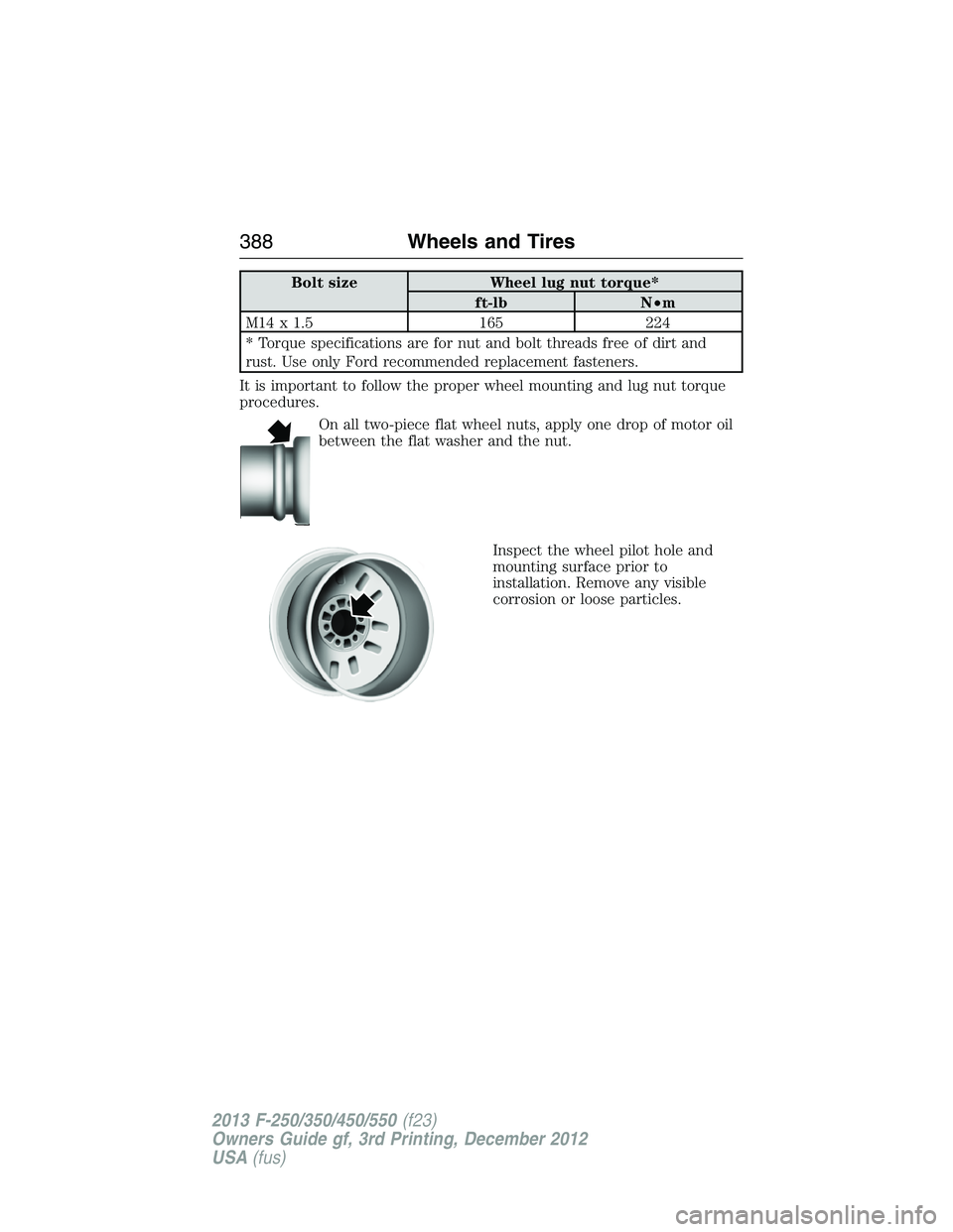
On all two-piece flat wheel nuts, apply one drop of motor oil
between the flat washer and the nut.
Inspect the wheel pilot hole and
mounting surface prior to
installation. Remove any visible
corrosion or loose particles.
388Wheels and Tires
2013 F-250/350/450/550(f23)
Owners Guide gf, 3rd Printing, December 2012
USA(fus)
Page 390 of 577
ENGINE SPECIFICATIONS
Engine 6.2L V8 engine 6.8L V10 engine
Cubic inches 378 413
Required fuelMinimum 87 octane or
Ethanol (E85)Minimum 87 octane
Firing order 1-5–4–8–6–3–7–2 1-6-5-10-2-7-3-8-4-9
Spark plug gap0.041–0.047 inch
(1.04–1.20 mm)0.039–0.043 inch
(1.0–1.1 mm)
Ignition system Coil on plug Coil on plug
Compression ratio 9.8:1 9.2:1
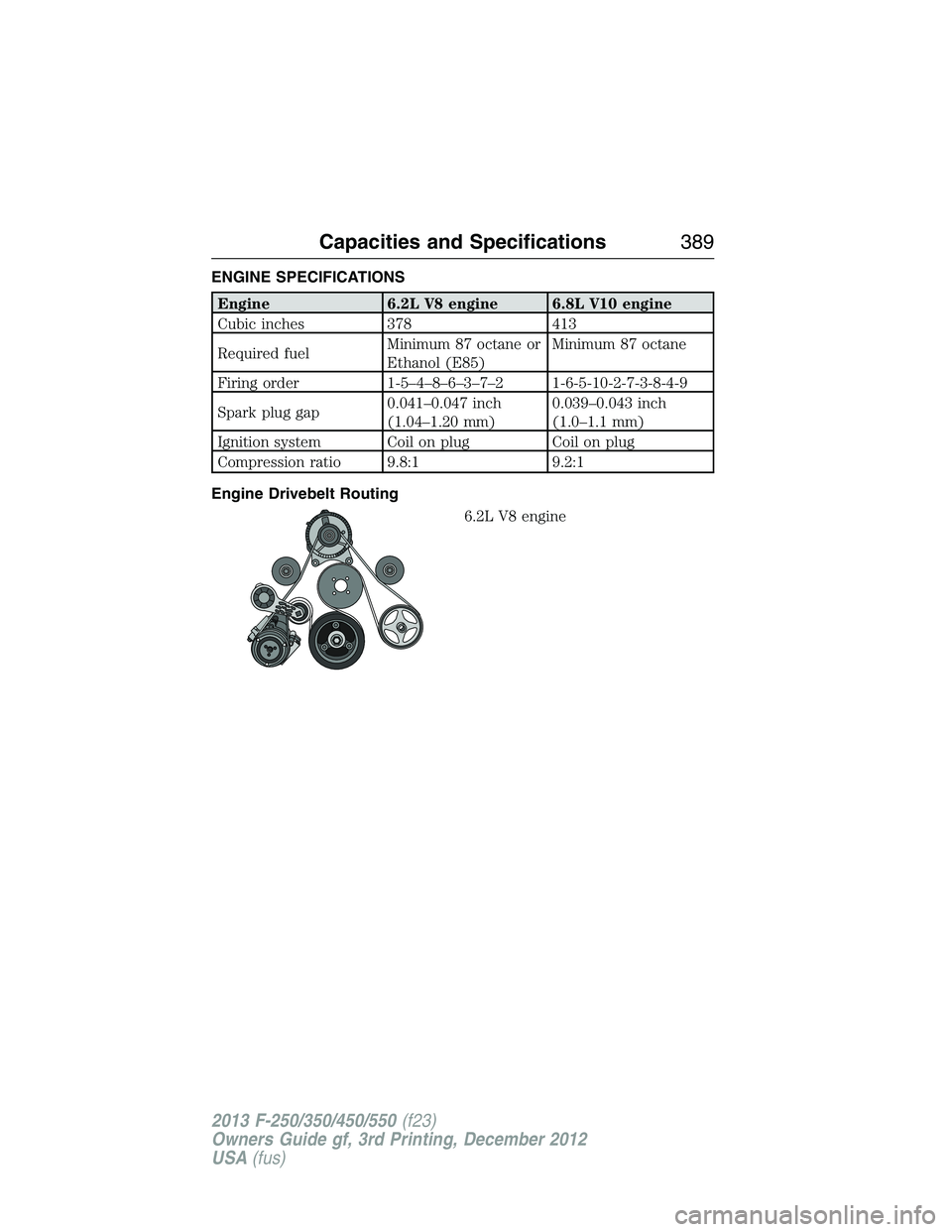
Engine Drivebelt Routing
6.2L V8 engine
Capacities and Specifications389
2013 F-250/350/450/550(f23)
Owners Guide gf, 3rd Printing, December 2012
USA(fus)