FORD F250 2014 Owners Manual
Manufacturer: FORD, Model Year: 2014, Model line: F250, Model: FORD F250 2014Pages: 460, PDF Size: 5.33 MB
Page 221 of 460
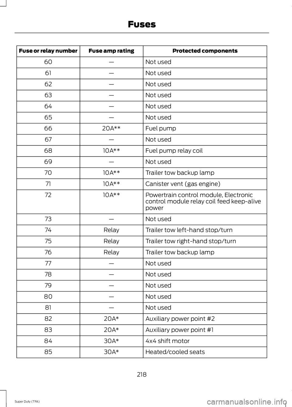
Protected components
Fuse amp rating
Fuse or relay number
Not used
—
60
Not used
—
61
Not used
—
62
Not used
—
63
Not used
—
64
Not used
—
65
Fuel pump
20A**
66
Not used
—
67
Fuel pump relay coil
10A**
68
Not used
—
69
Trailer tow backup lamp
10A**
70
Canister vent (gas engine)
10A**
71
Powertrain control module, Electronic
control module relay coil feed keep-alive
power
10A**
72
Not used
—
73
Trailer tow left-hand stop/turn
Relay
74
Trailer tow right-hand stop/turn
Relay
75
Trailer tow backup lamp
Relay
76
Not used
—
77
Not used
—
78
Not used
—
79
Not used
—
80
Not used
—
81
Auxiliary power point #2
20A*
82
Auxiliary power point #1
20A*
83
4x4 shift motor
30A*
84
Heated/cooled seats
30A*
85
218
Super Duty (TFA) Fuses
Page 222 of 460
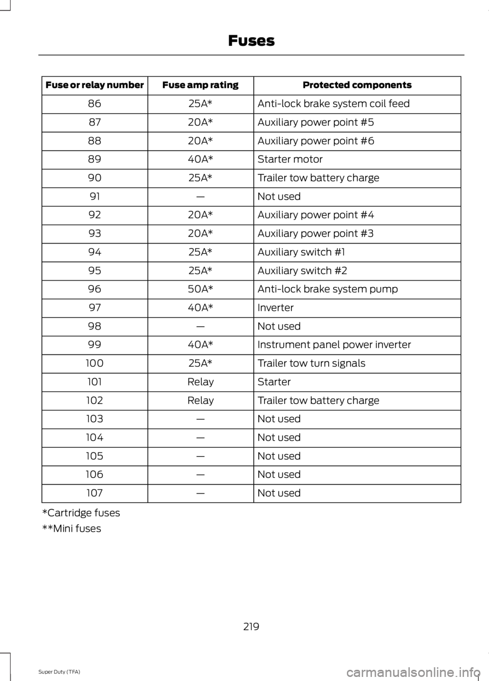
Protected components
Fuse amp rating
Fuse or relay number
Anti-lock brake system coil feed
25A*
86
Auxiliary power point #5
20A*
87
Auxiliary power point #6
20A*
88
Starter motor
40A*
89
Trailer tow battery charge
25A*
90
Not used
—
91
Auxiliary power point #4
20A*
92
Auxiliary power point #3
20A*
93
Auxiliary switch #1
25A*
94
Auxiliary switch #2
25A*
95
Anti-lock brake system pump
50A*
96
Inverter
40A*
97
Not used
—
98
Instrument panel power inverter
40A*
99
Trailer tow turn signals
25A*
100
Starter
Relay
101
Trailer tow battery charge
Relay
102
Not used
—
103
Not used
—
104
Not used
—
105
Not used
—
106
Not used
—
107
*Cartridge fuses
**Mini fuses
219
Super Duty (TFA) Fuses
Page 223 of 460
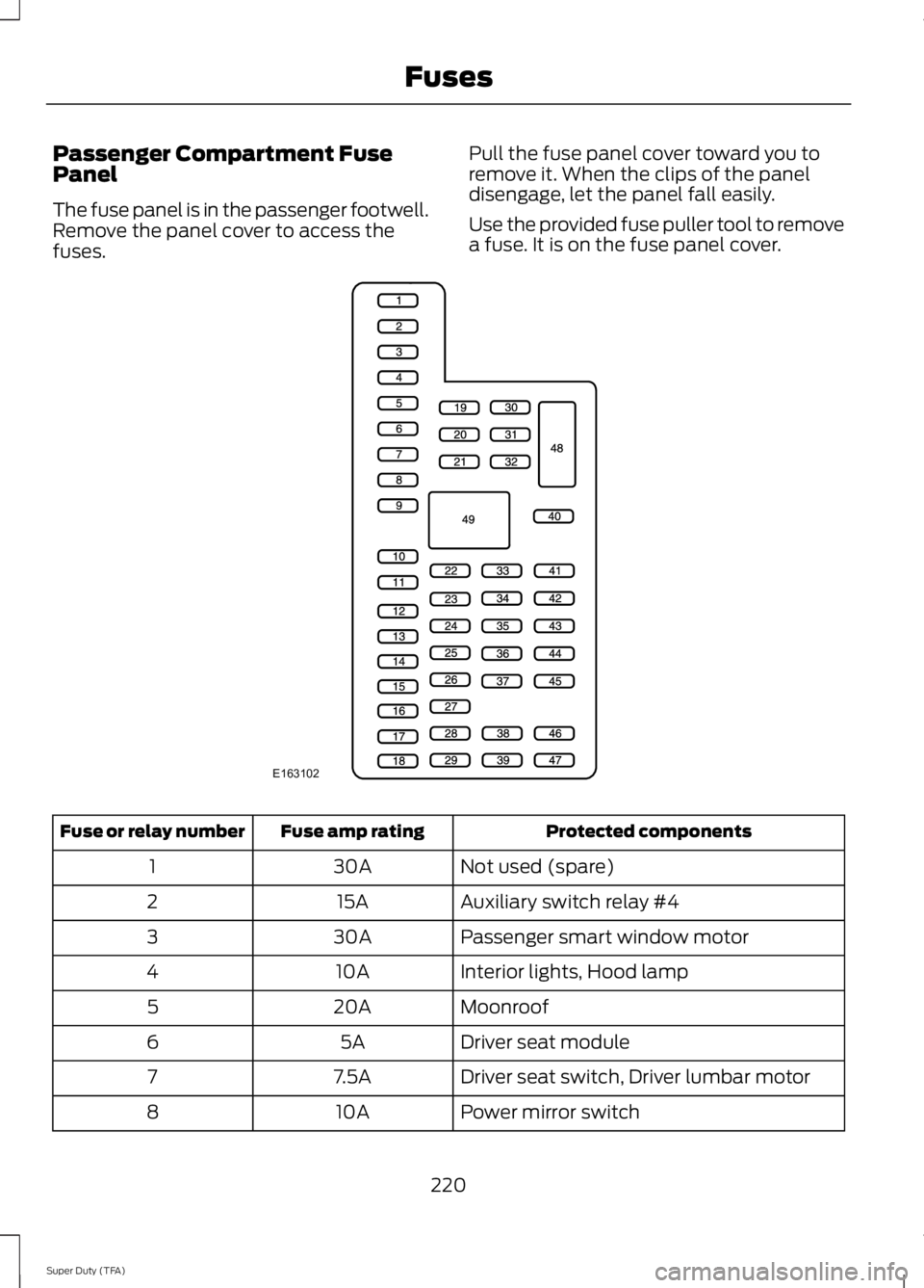
Passenger Compartment Fuse
Panel
The fuse panel is in the passenger footwell.
Remove the panel cover to access the
fuses.
Pull the fuse panel cover toward you to
remove it. When the clips of the panel
disengage, let the panel fall easily.
Use the provided fuse puller tool to remove
a fuse. It is on the fuse panel cover. Protected components
Fuse amp rating
Fuse or relay number
Not used (spare)
30A
1
Auxiliary switch relay #4
15A
2
Passenger smart window motor
30A
3
Interior lights, Hood lamp
10A
4
Moonroof
20A
5
Driver seat module
5A
6
Driver seat switch, Driver lumbar motor
7.5A
7
Power mirror switch
10A
8
220
Super Duty (TFA) FusesE163102
Page 224 of 460
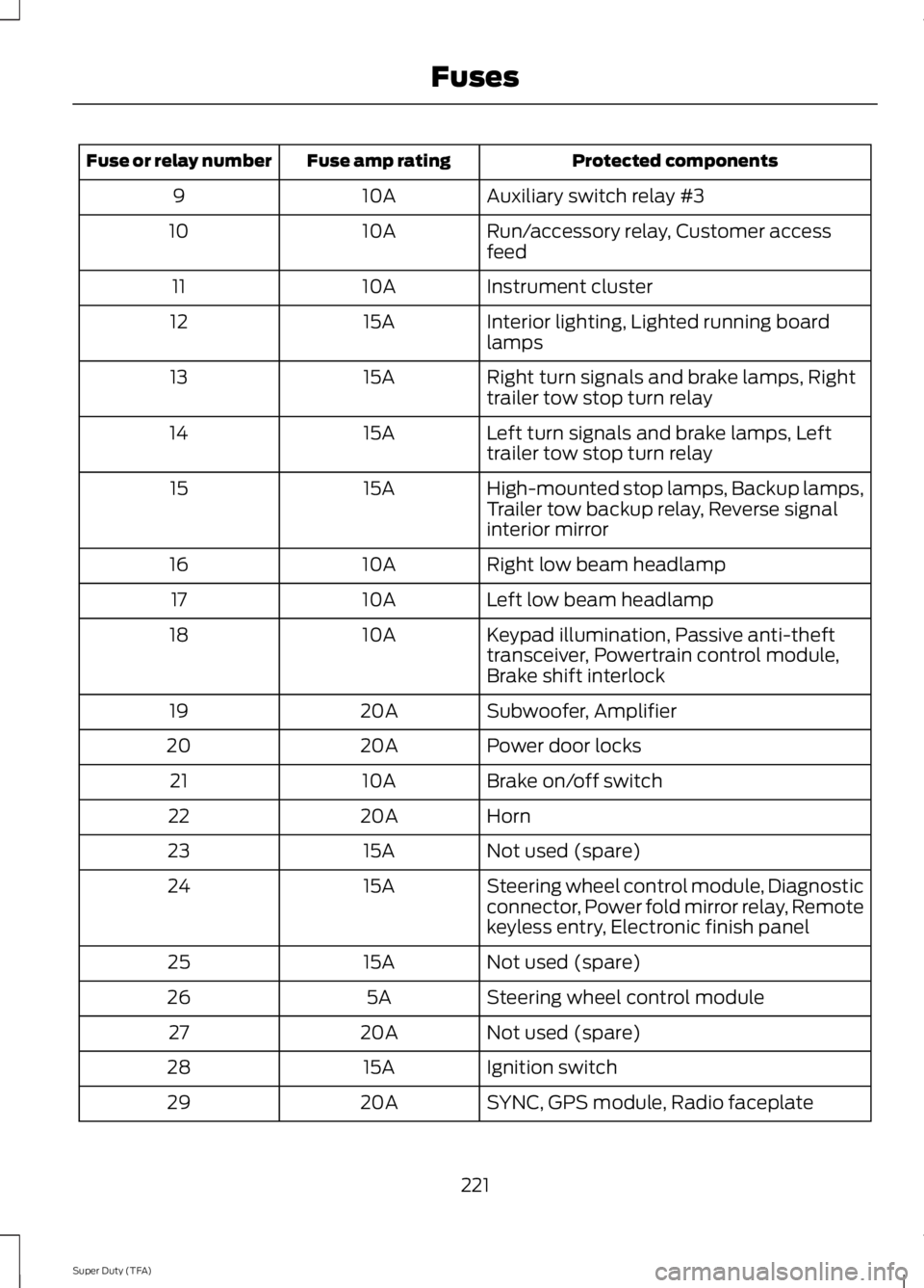
Protected components
Fuse amp rating
Fuse or relay number
Auxiliary switch relay #3
10A
9
Run/accessory relay, Customer access
feed
10A
10
Instrument cluster
10A
11
Interior lighting, Lighted running board
lamps
15A
12
Right turn signals and brake lamps, Right
trailer tow stop turn relay
15A
13
Left turn signals and brake lamps, Left
trailer tow stop turn relay
15A
14
High-mounted stop lamps, Backup lamps,
Trailer tow backup relay, Reverse signal
interior mirror
15A
15
Right low beam headlamp
10A
16
Left low beam headlamp
10A
17
Keypad illumination, Passive anti-theft
transceiver, Powertrain control module,
Brake shift interlock
10A
18
Subwoofer, Amplifier
20A
19
Power door locks
20A
20
Brake on/off switch
10A
21
Horn
20A
22
Not used (spare)
15A
23
Steering wheel control module, Diagnostic
connector, Power fold mirror relay, Remote
keyless entry, Electronic finish panel
15A
24
Not used (spare)
15A
25
Steering wheel control module
5A
26
Not used (spare)
20A
27
Ignition switch
15A
28
SYNC, GPS module, Radio faceplate
20A
29
221
Super Duty (TFA) Fuses
Page 225 of 460
Protected components
Fuse amp rating
Fuse or relay number
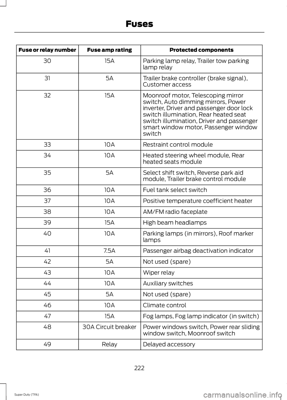
Parking lamp relay, Trailer tow parking
lamp relay
15A
30
Trailer brake controller (brake signal),
Customer access
5A
31
Moonroof motor, Telescoping mirror
switch, Auto dimming mirrors, Power
inverter, Driver and passenger door lock
switch illumination, Rear heated seat
switch illumination, Driver and passenger
smart window motor, Passenger window
switch
15A
32
Restraint control module
10A
33
Heated steering wheel module, Rear
heated seats module
10A
34
Select shift switch, Reverse park aid
module, Trailer brake control module
5A
35
Fuel tank select switch
10A
36
Positive temperature coefficient heater
10A
37
AM/FM radio faceplate
10A
38
High beam headlamps
15A
39
Parking lamps (in mirrors), Roof marker
lamps
10A
40
Passenger airbag deactivation indicator
7.5A
41
Not used (spare)
5A
42
Wiper relay
10A
43
Auxiliary switches
10A
44
Not used (spare)
5A
45
Climate control
10A
46
Fog lamps, Fog lamp indicator (in switch)
15A
47
Power windows switch, Power rear sliding
window switch, Moonroof switch
30A Circuit breaker
48
Delayed accessory
Relay
49
222
Super Duty (TFA) Fuses
Page 226 of 460
GENERAL INFORMATION
Have your vehicle serviced regularly to help
maintain its roadworthiness and resale
value. There is a large network of Ford
authorized dealers that are there to help
you with their professional servicing
expertise. We believe that their specially
trained technicians are best qualified to
service your vehicle properly and expertly.
They are supported by a wide range of
highly specialized tools developed
specifically for servicing your vehicle.
To help you service your vehicle, we
provide scheduled maintenance
information which makes tracking routine
service easy. See Scheduled
Maintenance (page 430).
If your vehicle requires professional service,
your authorized dealer can provide the
necessary parts and service. Check your
warranty information to find out which
parts and services are covered.
Use only recommended fuels, lubricants,
fluids and service parts conforming to
specifications. Motorcraft® parts are
designed and built to provide the best
performance in your vehicle.
Precautions
• Do not work on a hot engine.
• Make sure that nothing gets caught in
moving parts.
• Do not work on a vehicle with the
engine running in an enclosed space,
unless you are sure you have enough
ventilation.
• Keep all open flames and other burning
material (such as cigarettes) away
from the battery and all fuel related
parts. Working with the Engine Off
1. Set the parking brake and shift to
P
(Park).
2. Turn off the engine and remove the key
(if equipped).
3. Block the wheels.
Working with the Engine On WARNING
To reduce the risk of vehicle damage
and/or personal burn injuries, do not
start your engine with the air cleaner
removed and do not remove it while the
engine is running. 1. Set the parking brake and shift to
P
(Park).
2. Block the wheels
OPENING AND CLOSING THE
HOOD 1.
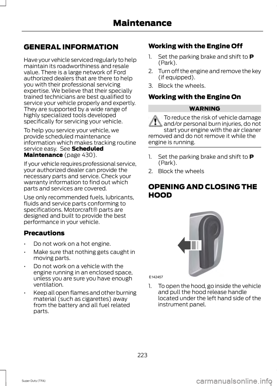
To open the hood, go inside the vehicle
and pull the hood release handle
located under the left hand side of the
instrument panel.
223
Super Duty (TFA) MaintenanceE142457
Page 227 of 460
2. Go to the front of the vehicle and
locate the secondary release lever,
which is located under the front of the
hood, to your right of the center of the
vehicle (driver's side), toward the
headlight.
3. Release the hood latch by pushing the secondary release lever to your left,
toward the center of the vehicle.
4. Raise the hood. 5.
To close the hood, lower the hood and
allow it to drop the last 8 to 11 inches
(20 to 30 centimeters).
Note: Make sure that the hood is closed
properly.
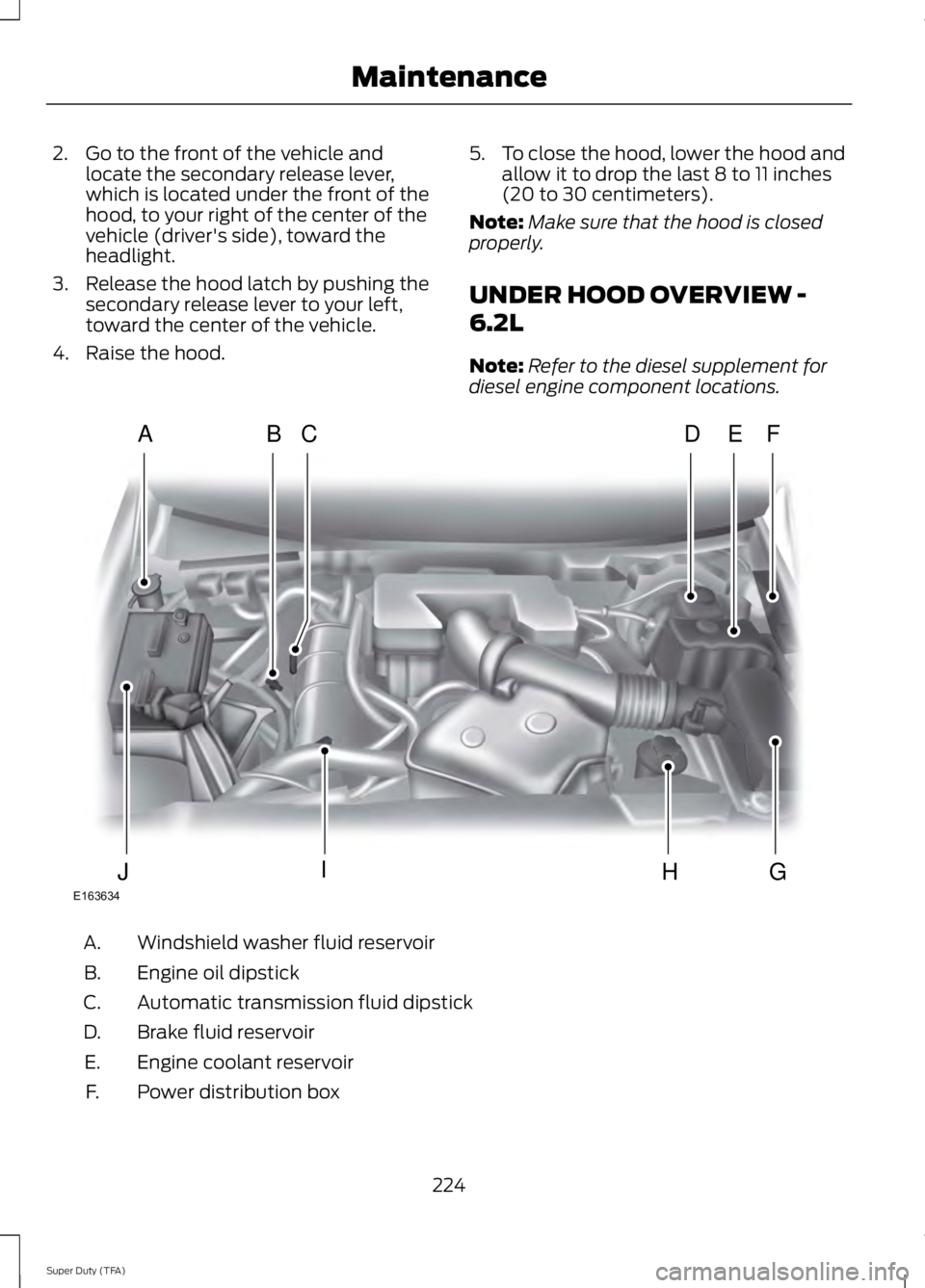
UNDER HOOD OVERVIEW -
6.2L
Note: Refer to the diesel supplement for
diesel engine component locations. Windshield washer fluid reservoir
A.
Engine oil dipstick
B.
Automatic transmission fluid dipstick
C.
Brake fluid reservoir
D.
Engine coolant reservoir
E.
Power distribution box
F.
224
Super Duty (TFA) MaintenanceE163634
ADFEBC
GHIJ
Page 228 of 460
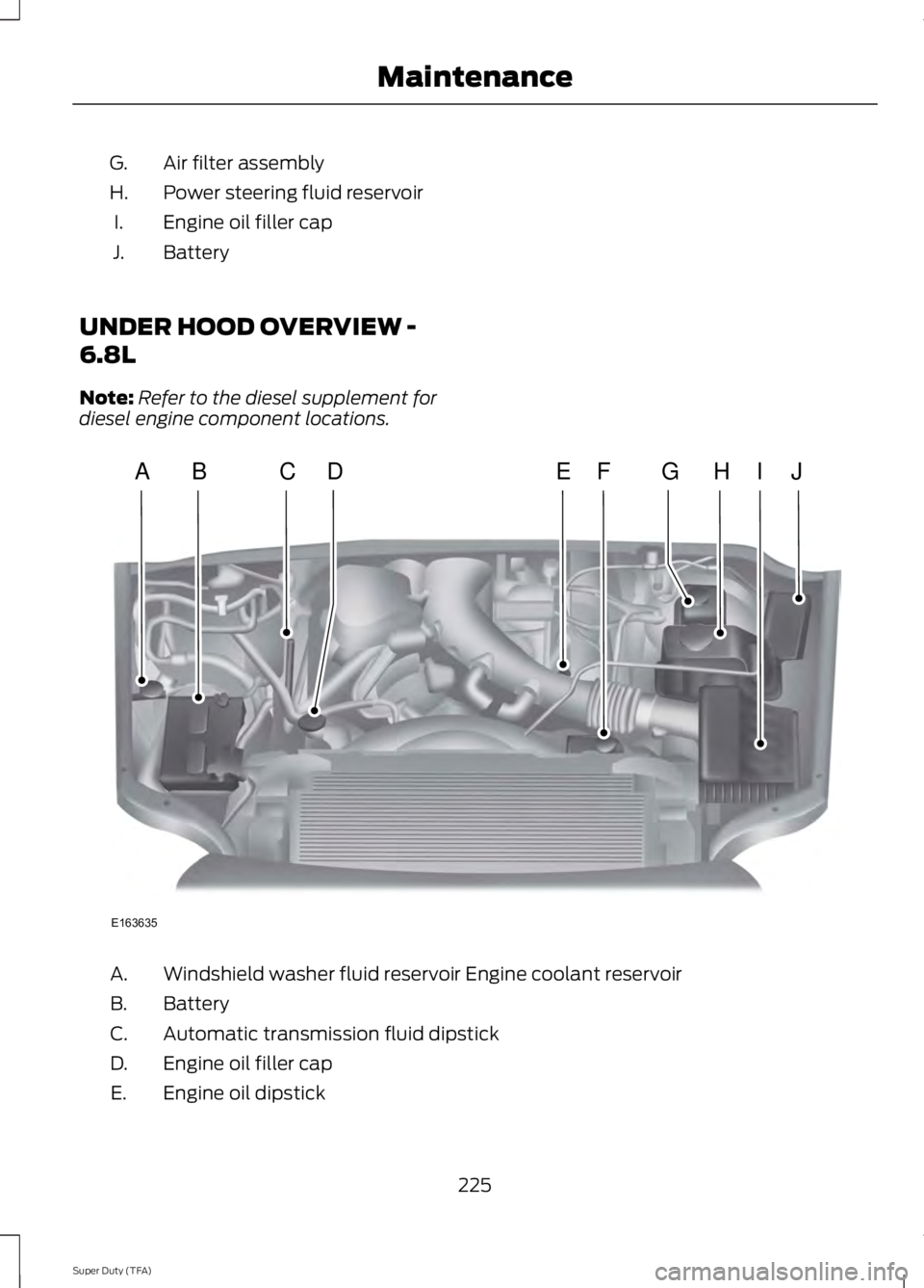
Air filter assembly
G.
Power steering fluid reservoir
H.
Engine oil filler cap
I.
Battery
J.
UNDER HOOD OVERVIEW -
6.8L
Note: Refer to the diesel supplement for
diesel engine component locations. Windshield washer fluid reservoir Engine coolant reservoir
A.
Battery
B.
Automatic transmission fluid dipstick
C.
Engine oil filler cap
D.
Engine oil dipstick
E.
225
Super Duty (TFA) MaintenanceE163635
ABCEHIJFDG
Page 229 of 460
Power steering fluid reservoir
F.
Brake fluid reservoir
G.
Engine coolant reservoir
H.
Air filter assembly
I.
Power distribution box
J.
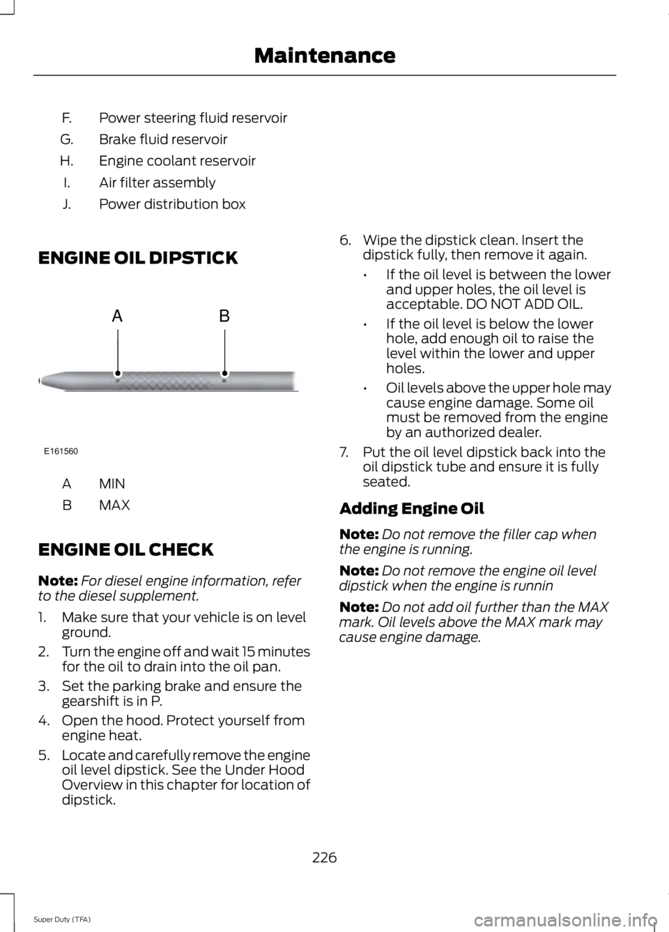
ENGINE OIL DIPSTICK MINA
MAX
B
ENGINE OIL CHECK
Note: For diesel engine information, refer
to the diesel supplement.
1. Make sure that your vehicle is on level ground.
2. Turn the engine off and wait 15 minutes
for the oil to drain into the oil pan.
3. Set the parking brake and ensure the gearshift is in P.
4. Open the hood. Protect yourself from engine heat.
5. Locate and carefully remove the engine
oil level dipstick. See the Under Hood
Overview in this chapter for location of
dipstick. 6. Wipe the dipstick clean. Insert the
dipstick fully, then remove it again.
•If the oil level is between the lower
and upper holes, the oil level is
acceptable. DO NOT ADD OIL.
• If the oil level is below the lower
hole, add enough oil to raise the
level within the lower and upper
holes.
• Oil levels above the upper hole may
cause engine damage. Some oil
must be removed from the engine
by an authorized dealer.
7. Put the oil level dipstick back into the oil dipstick tube and ensure it is fully
seated.
Adding Engine Oil
Note: Do not remove the filler cap when
the engine is running.
Note: Do not remove the engine oil level
dipstick when the engine is runnin
Note: Do not add oil further than the MAX
mark. Oil levels above the MAX mark may
cause engine damage.
226
Super Duty (TFA) MaintenanceE161560
AB
Page 230 of 460
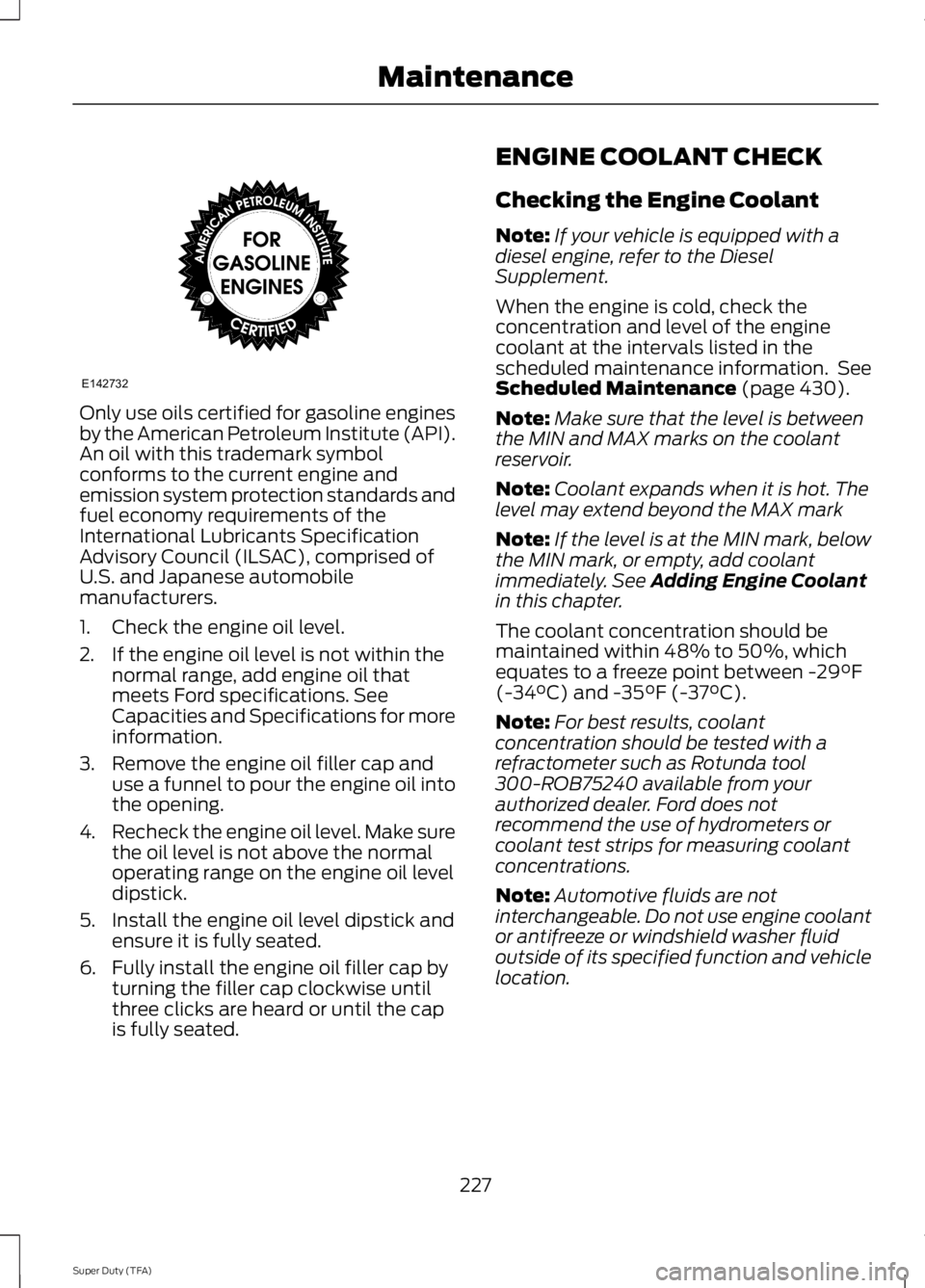
Only use oils certified for gasoline engines
by the American Petroleum Institute (API).
An oil with this trademark symbol
conforms to the current engine and
emission system protection standards and
fuel economy requirements of the
International Lubricants Specification
Advisory Council (ILSAC), comprised of
U.S. and Japanese automobile
manufacturers.
1. Check the engine oil level.
2. If the engine oil level is not within the
normal range, add engine oil that
meets Ford specifications. See
Capacities and Specifications for more
information.
3. Remove the engine oil filler cap and use a funnel to pour the engine oil into
the opening.
4. Recheck the engine oil level. Make sure
the oil level is not above the normal
operating range on the engine oil level
dipstick.
5. Install the engine oil level dipstick and ensure it is fully seated.
6. Fully install the engine oil filler cap by turning the filler cap clockwise until
three clicks are heard or until the cap
is fully seated. ENGINE COOLANT CHECK
Checking the Engine Coolant
Note:
If your vehicle is equipped with a
diesel engine, refer to the Diesel
Supplement.
When the engine is cold, check the
concentration and level of the engine
coolant at the intervals listed in the
scheduled maintenance information. See
Scheduled Maintenance (page 430).
Note: Make sure that the level is between
the MIN and MAX marks on the coolant
reservoir.
Note: Coolant expands when it is hot. The
level may extend beyond the MAX mark
Note: If the level is at the MIN mark, below
the MIN mark, or empty, add coolant
immediately. See
Adding Engine Coolant
in this chapter.
The coolant concentration should be
maintained within 48% to 50%, which
equates to a freeze point between
-29°F
(-34°C) and -35°F (-37°C).
Note: For best results, coolant
concentration should be tested with a
refractometer such as Rotunda tool
300-ROB75240 available from your
authorized dealer. Ford does not
recommend the use of hydrometers or
coolant test strips for measuring coolant
concentrations.
Note: Automotive fluids are not
interchangeable. Do not use engine coolant
or antifreeze or windshield washer fluid
outside of its specified function and vehicle
location.
227
Super Duty (TFA) MaintenanceE142732