key FORD F250 2014 Service Manual
[x] Cancel search | Manufacturer: FORD, Model Year: 2014, Model line: F250, Model: FORD F250 2014Pages: 460, PDF Size: 5.33 MB
Page 166 of 460
PRINCIPLE OF OPERATION
The traction control system helps avoid
drive wheel spin and loss of traction.
If your vehicle begins to slide, the system
applies the brakes to individual wheels
and, when needed, reduces engine power
at the same time. If the wheels spin when
accelerating on slippery or loose surfaces,
the system reduces engine power in order
to increase traction.
USING TRACTION CONTROL
(Dual rear wheel vehicles only)
In certain situations (for example, stuck in
snow or mud), it may be beneficial to turn
the traction control system off. This allows
the wheels to spin with full engine power.
Turn the traction control system off by
pressing the stability control button
located on the instrument panel.
If you cannot turn the system off, see the
MyKey chapter for more information.
Placing your vehicle into four-wheel drive
mode automatically disables traction
control. Traction control operation will
resume when you place your vehicle back
into two-wheel drive mode.
Engine only traction control
(Dual rear wheel vehicles only)
Traction control system
Stability control OFF
indicator
Button functions
Enabled
Not illuminated
Default at start-up
Disabled
Illuminated
Button pressed momentarily
Enabled
Not illuminated
Button pressed again after
deactivation
Disabled
Illuminated
Transfer case switched to
4WD*
*Engaging 4WD automatically disables the traction control system.
163
Super Duty (TFA) Traction ControlE162724
Page 173 of 460
PARKING AID (IF EQUIPPED)
WARNINGS
To help avoid personal injury, please
read and understand the limitations
of the system as contained in this
section. Sensing is only an aid for some
(generally large and fixed) objects when
moving in reverse on a flat surface at
parking speeds. Traffic control systems,
inclement weather, air brakes, and external
motors and fans may also affect the
function of the sensing system; this may
include reduced performance or a false
activation. To help avoid personal injury, always
use caution when in R (Reverse) and
when using the sensing system.
This system is not designed to
prevent contact with small or moving
objects. The system is designed to
provide a warning to assist the driver in
detecting large stationary objects to avoid
damaging the vehicle. The system may not
detect smaller objects, particularly those
close to the ground. Certain add-on devices such as large
trailer hitches, bike or surfboard racks
and any device that may block the
normal detection zone of the system, may
create false beeps. Note:
Keep the sensors, located on the
bumper or fascia, free from snow, ice and
large accumulations of dirt. If the sensors
are covered, the system ’s accuracy can be
affected. Do not clean the sensors with
sharp objects.
Note: If your vehicle sustains damage to
the bumper or fascia, leaving it misaligned
or bent, the sensing zone may be altered
causing inaccurate measurement of
obstacles or false alarms. Note:
If your vehicle is equipped with
MyKey ™, it is possible to prevent turning
the sensing system off. See MyKey ™
(page
50).
Note: If your vehicle is equipped with a fully
integrated electronic trailer brake controller
(TBC) and a trailer with electric trailer
brakes is connected to your vehicle, the RSS
will be disabled. When the vehicle is shifted
into reverse, the information display will
remain in the Rear Park Aid Off selection.
For more information on the TBC, See
Trailer Sway Control
(page 188).
The sensing system warns the driver of
obstacles within a certain range of the
bumper area. The system turns on
automatically whenever the ignition is
switched on.
When receiving a detection warning, the
radio volume is reduced to a
predetermined level. After the warning
goes away, the radio volume returns to the
previous level.
Rear Sensing System
The rear sensors are only active when the
transmission is in R (Reverse). As the
vehicle moves closer to the obstacle, the
rate of the audible warning increases.
When the obstacle is fewer than 12 inches
(30 centimeters) away, the warning
sounds continuously. If a stationary or
receding object is detected farther than 12
inches (30 centimeters) from the side of
the vehicle, the tone sounds for only three
seconds. Once the system detects an
object approaching, the warning sounds
again.
170
Super Duty (TFA) Parking Aids
Page 186 of 460
be: 635 kilograms - (2 x 99
kilograms) - (12 x 45 kilograms) =
635 - 198 - 540 = -103 kilograms.
You will need to reduce the load
weight by at least 240 pounds
(104 kilograms). If you remove
three 100-pound (45-kilogram)
cement bags, then the load
calculation would be:1400 - (2 x
220) - (9 x 100) = 1400 - 440 -
900 = 60 pounds. Now you have
the load capacity to transport the
cement and your friend home. In
metric units, the calculation would
be: 635 kilograms - (2 x 99
kilograms) - (9 x 45 kilograms) =
635 - 198 - 405 = 32 kilograms.
The above calculations also
assume that the loads are
positioned in your vehicle in a
manner that does not overload
the Front or the Rear Gross Axle
Weight Rating specified for your
vehicle on the Safety Compliance
Certification Label. The label shall
be affixed to either the door hinge
pillar, door-latch post, or the door
edge that meets the door-latch
post, next to the driver's seating
position.
Special Loading Instructions
for Owners of Pick-up Trucks
and Utility-type Vehicles WARNING
Loaded vehicles may handle
differently than unloaded
vehicles. Extra precautions, such
as slower speeds and increased
stopping distance, should be
taken when driving a heavily
loaded vehicle. Your vehicle can haul more cargo
and people than most passenger
cars. Depending upon the type
and placement of the load,
hauling cargo and people may
raise the center of gravity of the
vehicle.
TAILGATE
Tailgate Lock
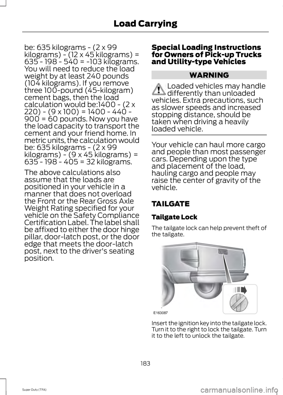
The tailgate lock can help prevent theft of
the tailgate.
Insert the ignition key into the tailgate lock.
Turn it to the right to lock the tailgate. Turn
it to the left to unlock the tailgate.
183
Super Duty (TFA) Load CarryingE163087
Page 207 of 460
ROADSIDE ASSISTANCE
Vehicles Sold In The U.S.: Getting
Roadside Assistance
To fully assist you should you have a
vehicle concern, Ford Motor Company
offers a complimentary roadside
assistance program. This program is
separate from the New Vehicle Limited
Warranty. The service is available:
•
24 hours, seven days a week.
• for the coverage period listed on the
Roadside Assistance Card included in
your Owner's Manual portfolio.
Roadside assistance will cover:
• a flat tire change with a good spare, if
provided with the vehicle (except
vehicles that have been supplied with
a tire inflation kit).
• battery jump start.
• lock-out assistance (key replacement
cost is the customer's responsibility).
• fuel delivery — Independent Service
Contractors, if not prohibited by state,
local or municipal law, shall deliver up
to 2.0 gallons (7.5 liters) of gasoline or
5.0 gallons (18.9 liters) of diesel fuel
to a disabled vehicle. Fuel delivery
service is limited to two no-charge
occurrences within a 12-month period.
• winch out — available within 100 feet
(30.5 meters) of a paved or county
maintained road, no recoveries.
• towing — Ford and Lincoln eligible
vehicles towed to an authorized dealer
within 35 miles (56.3 kilometers) of the
disablement location or to the nearest
authorized dealer. If a member
requests to be towed to an authorized
dealer more than 35 miles (56.3
kilometers) from the disablement
location, the member shall be
responsible for any mileage costs in
excess of 35 miles (56.3 kilometers). Trailers shall be covered up to $200 if the
disabled eligible vehicle requires service at
the nearest authorized dealer. If the trailer
is disabled, but the towing vehicle is
operational, the trailer does not qualify for
any roadside services.
Vehicles Sold In The U.S. : Using
Roadside Assistance
Complete the roadside assistance
identification card and place it in your
wallet for quick reference. This card is
found in the owner's information portfolio
in the glove compartment.
U.S. Ford vehicle customers who require
Roadside Assistance, call 1-800-241-3673.
If you need to arrange roadside assistance
for yourself, Ford Motor Company will
reimburse a reasonable amount for towing
to the nearest dealership within 35 miles
(56.3 kilometers). To obtain
reimbursement information, U.S. Ford
vehicle customers call 1-800-241-3673.
Customers will be asked to submit their
original receipts.
Vehicles Sold In Canada : Getting
Roadside Assistance
Canadian customers who require roadside
assistance, call 1-800-665-2006.
Vehicles Sold In Canada : Using
Roadside Assistance
For your convenience, you may complete
the roadside assistance identification card
found in the centerfold of your warranty
guide and retain for future reference.
Canadian roadside coverage and benefits
may differ from the U.S. coverage. If you
require more information, please refer to
the coverage section of your warranty
guide, call us in Canada at
1-800-665-2006, or visit our website at
www.ford.ca.
204
Super Duty (TFA) Roadside Emergencies
Page 208 of 460
HAZARD WARNING FLASHERS
Note:
The hazard warning flashers will
operate when the ignition is in any position
or if the key is not in the ignition. If used
when the engine is not running, the battery
will lose charge. As a result, there may be
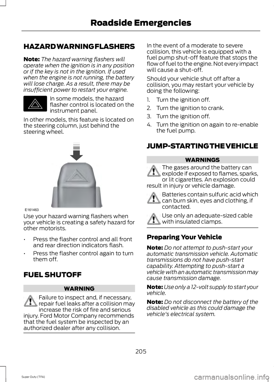
insufficient power to restart your engine. In some models, the hazard
flasher control is located on the
instrument panel.
In other models, this feature is located on
the steering column, just behind the
steering wheel. Use your hazard warning flashers when
your vehicle is creating a safety hazard for
other motorists.
•
Press the flasher control and all front
and rear direction indicators flash.
• Press the flasher control again to turn
them off.
FUEL SHUTOFF WARNING
Failure to inspect and, if necessary,
repair fuel leaks after a collision may
increase the risk of fire and serious
injury. Ford Motor Company recommends
that the fuel system be inspected by an
authorized dealer after any collision. In the event of a moderate to severe
collision, this vehicle is equipped with a
fuel pump shut-off feature that stops the
flow of fuel to the engine. Not every impact
will cause a shut-off.
Should your vehicle shut off after a
collision, you may restart your vehicle by
doing the following:
1. Turn the ignition off.
2. Turn the ignition to crank.
3. Turn the ignition off.
4.
Turn the ignition on again to re-enable
the fuel pump.
JUMP-STARTING THE VEHICLE WARNINGS
The gases around the battery can
explode if exposed to flames, sparks,
or lit cigarettes. An explosion could
result in injury or vehicle damage. Batteries contain sulfuric acid which
can burn skin, eyes and clothing, if
contacted.
Use only an adequate-sized cable
with insulated clamps.
Preparing Your Vehicle
Note:
Do not attempt to push-start your
automatic transmission vehicle. Automatic
transmissions do not have push-start
capability. Attempting to push-start a
vehicle with an automatic transmission may
cause transmission damage.
Note: Use only a 12-volt supply to start your
vehicle.
Note: Do not disconnect the battery of the
disabled vehicle as this could damage the
vehicle's electrical system.
205
Super Duty (TFA) Roadside EmergenciesE142663 E161463
Page 224 of 460
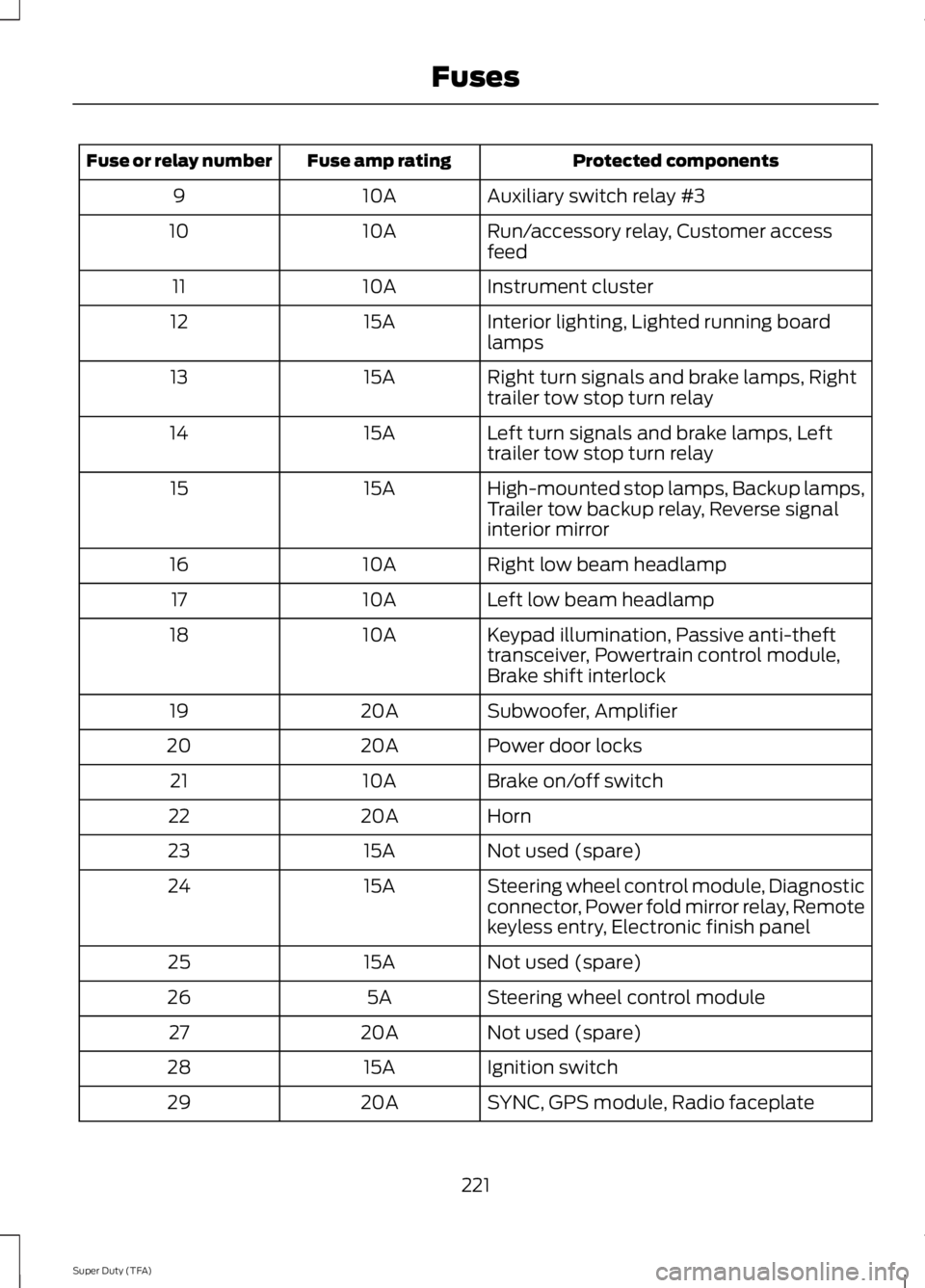
Protected components
Fuse amp rating
Fuse or relay number
Auxiliary switch relay #3
10A
9
Run/accessory relay, Customer access
feed
10A
10
Instrument cluster
10A
11
Interior lighting, Lighted running board
lamps
15A
12
Right turn signals and brake lamps, Right
trailer tow stop turn relay
15A
13
Left turn signals and brake lamps, Left
trailer tow stop turn relay
15A
14
High-mounted stop lamps, Backup lamps,
Trailer tow backup relay, Reverse signal
interior mirror
15A
15
Right low beam headlamp
10A
16
Left low beam headlamp
10A
17
Keypad illumination, Passive anti-theft
transceiver, Powertrain control module,
Brake shift interlock
10A
18
Subwoofer, Amplifier
20A
19
Power door locks
20A
20
Brake on/off switch
10A
21
Horn
20A
22
Not used (spare)
15A
23
Steering wheel control module, Diagnostic
connector, Power fold mirror relay, Remote
keyless entry, Electronic finish panel
15A
24
Not used (spare)
15A
25
Steering wheel control module
5A
26
Not used (spare)
20A
27
Ignition switch
15A
28
SYNC, GPS module, Radio faceplate
20A
29
221
Super Duty (TFA) Fuses
Page 226 of 460
GENERAL INFORMATION
Have your vehicle serviced regularly to help
maintain its roadworthiness and resale
value. There is a large network of Ford
authorized dealers that are there to help
you with their professional servicing
expertise. We believe that their specially
trained technicians are best qualified to
service your vehicle properly and expertly.
They are supported by a wide range of
highly specialized tools developed
specifically for servicing your vehicle.
To help you service your vehicle, we
provide scheduled maintenance
information which makes tracking routine
service easy. See Scheduled
Maintenance (page 430).
If your vehicle requires professional service,
your authorized dealer can provide the
necessary parts and service. Check your
warranty information to find out which
parts and services are covered.
Use only recommended fuels, lubricants,
fluids and service parts conforming to
specifications. Motorcraft® parts are
designed and built to provide the best
performance in your vehicle.
Precautions
• Do not work on a hot engine.
• Make sure that nothing gets caught in
moving parts.
• Do not work on a vehicle with the
engine running in an enclosed space,
unless you are sure you have enough
ventilation.
• Keep all open flames and other burning
material (such as cigarettes) away
from the battery and all fuel related
parts. Working with the Engine Off
1. Set the parking brake and shift to
P
(Park).
2. Turn off the engine and remove the key
(if equipped).
3. Block the wheels.
Working with the Engine On WARNING
To reduce the risk of vehicle damage
and/or personal burn injuries, do not
start your engine with the air cleaner
removed and do not remove it while the
engine is running. 1. Set the parking brake and shift to
P
(Park).
2. Block the wheels
OPENING AND CLOSING THE
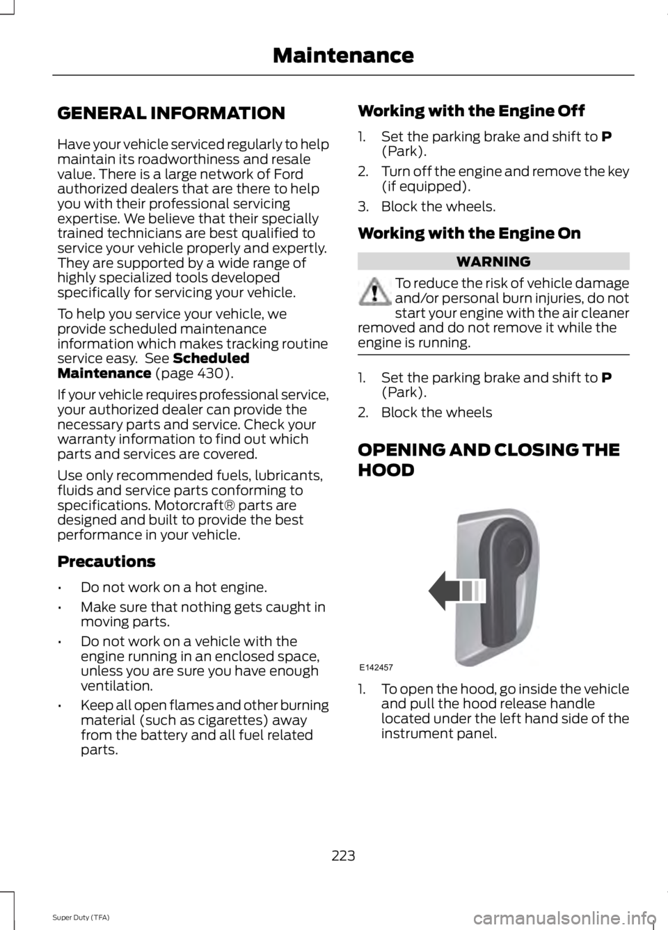
HOOD 1.
To open the hood, go inside the vehicle
and pull the hood release handle
located under the left hand side of the
instrument panel.
223
Super Duty (TFA) MaintenanceE142457
Page 240 of 460
control fan, heated steering wheel, audio
and navigation system. A message may be
shown in the information displays to alert
the driver that battery protection actions
are active. These messages are only for
notification that an action is taking place,
and not intended to indicate an electrical
problem or that the battery requires
replacement.
Electrical accessory installation
To ensure proper operation of the BMS,
any electrical devices that are added to
the vehicle should not have their ground
connection made directly at the negative
battery post. A connection at the negative
battery post can cause inaccurate
measurements of the battery condition
and potential incorrect system operation.
Note:
Electrical or electronic accessories
added to the vehicle by the dealer or the
owner may adversely affect battery
performance and durability, and may also
affect the performance of other electrical
systems in the vehicle.
When a battery replacement is required,
the battery should only be replaced with
a Ford recommended replacement battery
which matches the electrical requirements
of the vehicle. After battery replacement,
or in some cases after charging the battery
with the external charger, the BMS requires
eight hours of vehicle sleep time (key off
with doors closed) to relearn the new
battery state of charge. Prior to relearning
the state of charge, the BMS may disable
electrical features (to protect the battery)
earlier than normal. CHECKING THE WIPER
BLADES Run the tip of your fingers over the edge of
the blade to check for roughness.
Clean the wiper blades with washer fluid
or water applied with a soft sponge or
cloth.
CHANGING THE WIPER
BLADES
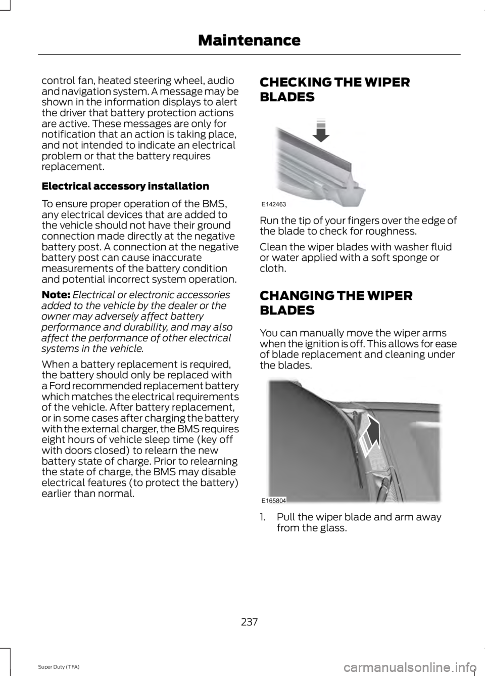
You can manually move the wiper arms
when the ignition is off. This allows for ease
of blade replacement and cleaning under
the blades.
1. Pull the wiper blade and arm away
from the glass.
237
Super Duty (TFA) MaintenanceE142463 E165804
Page 281 of 460
•
To reduce the chances of interference
from another vehicle, perform the
system reset procedure at least three
feet (one meter) away from another
Ford Motor Company vehicle
undergoing the system reset procedure
at the same time.
• Do not wait more than two minutes
between resetting each tire sensor or
the system will time-out and the entire
procedure will have to be repeated on
all four wheels.
• A double horn will sound indicating the
need to repeat the procedure.
Performing the System Reset Procedure
Read the entire procedure before
attempting.
1. Drive the vehicle above 20 mph (32 km/h) for at least two minutes, then
park in a safe location where you can
easily get to all four tires and have
access to an air pump.
2. Place the ignition in the off position and
keep the key in the ignition.
3. Cycle the ignition to the on position with the engine off.
4. Turn the hazard flashers on then off three times. You must accomplish this
within 10 seconds. If the reset mode
has been entered successfully, the horn
will sound once, the system indicator
will flash and a message is shown in
the information display. If this does not
occur, please try again starting at Step
2. If after repeated attempts to enter
the reset mode, the horn does not
sound, the system indicator does not
flash and no message is shown in the
information display, seek service from
your authorized dealer. 5. Train the tire pressure monitoring
system sensors in the tires using the
following system reset sequence
starting with the left front tire in the
following clockwise order: Left front
(driver's side front tire), Right front
(passenger's side front tire), Right rear
(passenger's side rear tire), Left rear
(driver's side rear tire)
6. Remove the valve cap from the valve stem on the left front tire. Decrease the
air pressure until the horn sounds.
Note: The single horn chirp confirms
that the sensor identification code has
been learned by the module for this
position. If a double horn is heard, the
reset procedure was unsuccessful, and
you must repeat it.
7. Remove the valve cap from the valve stem on the right front tire. Decrease
the air pressure until the horn sounds.
8. Remove the valve cap from the valve stem on the right rear tire. Decrease the
air pressure until the horn sounds.
9. Remove the valve cap from the valve stem on the left rear tire. Decrease the
air pressure until the horn sounds.
Training is complete after the horn
sounds for the last tire trained (driver's
side rear tire), the system indicator
stops flashing, and a message is shown
in the information display.
10. Turn the ignition off. If two short horn
beeps are heard, the reset procedure
was unsuccessful and you must
repeat it. If after repeating the
procedure and two short beeps are
heard when the ignition is turned to
off, seek assistance from your
authorized dealer.
278
Super Duty (TFA) Wheels and Tires
Page 284 of 460
Location
Tool
SuperCab: Under rear bench seat onpassenger side
Regular cab: Fastened to floor behind driver seat
Jack handle, lug wrench, lug wrench exten-
sion (only available on dual rear wheel
vehicles) and wheel chock (only available
on single rear wheel vehicles equipped with a diesel engine) SuperCab: Fastened to floor under rear seat
Crew Cab: Fastened to floor behind rear seat at driver side
In the glove box
Key and spare tire lock
Removing the Spare Tire (With
Spare Tire Carrier Only)
The following tools are required to remove
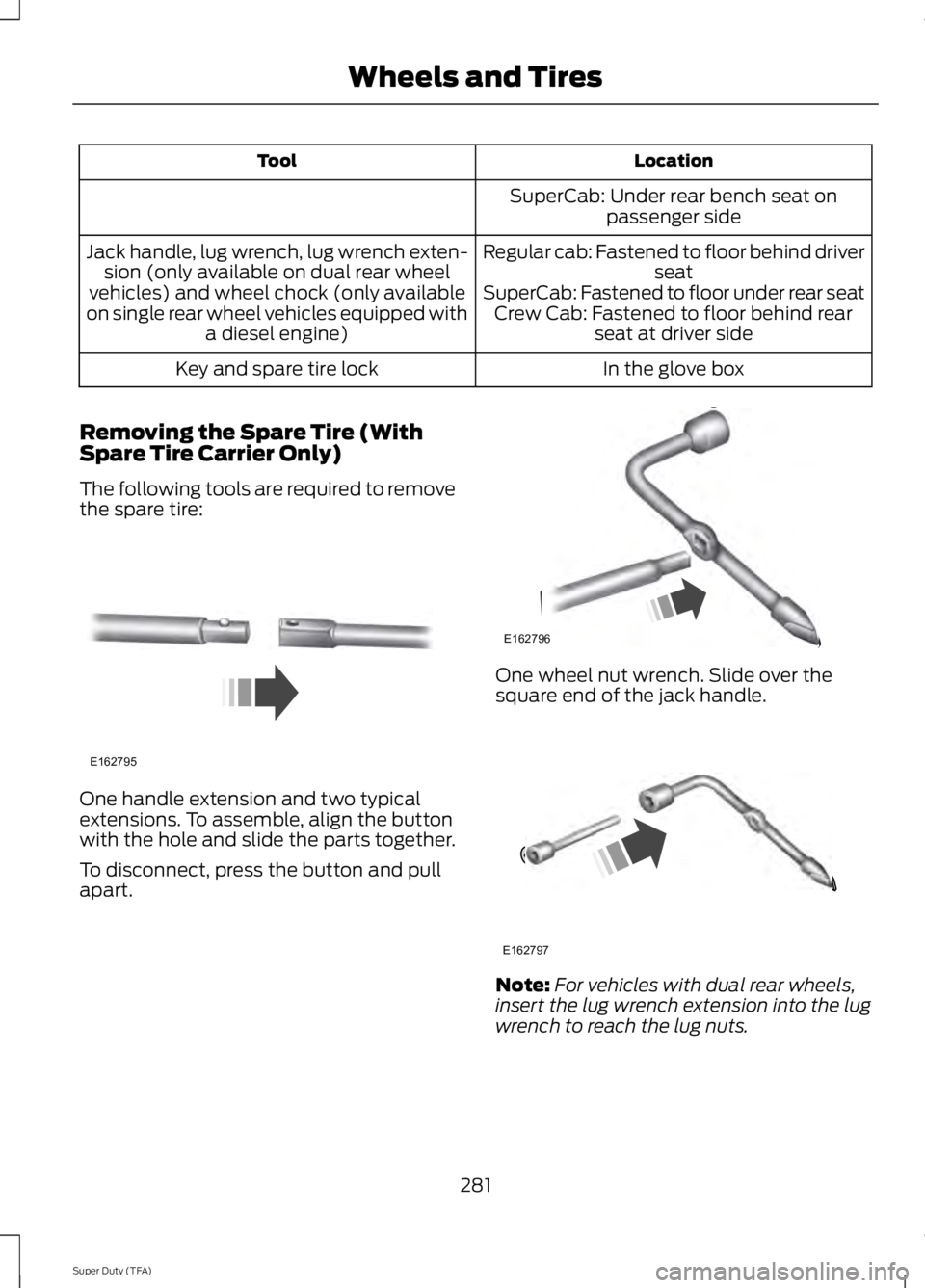
the spare tire: One handle extension and two typical
extensions. To assemble, align the button
with the hole and slide the parts together.
To disconnect, press the button and pull
apart. One wheel nut wrench. Slide over the
square end of the jack handle.
Note:
For vehicles with dual rear wheels,
insert the lug wrench extension into the lug
wrench to reach the lug nuts.
281
Super Duty (TFA) Wheels and TiresE162795 E162796 E162797