transmission fluid FORD F250 2016 Owners Manual
[x] Cancel search | Manufacturer: FORD, Model Year: 2016, Model line: F250, Model: FORD F250 2016Pages: 507, PDF Size: 6.81 MB
Page 7 of 507
Reporting Safety Defects (U.S.
Only)..............................................................221
Reporting Safety Defects (Canada Only).............................................................222
Fuses
Fuse Specification Chart...........................223
Changing a Fuse............................................231
Maintenance
General Information
....................................232
Opening and Closing the Hood..............232
Under Hood Overview - 6.2L...................233
Under Hood Overview - 6.8L..................234
Engine Oil Dipstick......................................235
Engine Oil Check
..........................................235
Oil Change Indicator Reset......................236
Engine Coolant Check
...............................236
Automatic Transmission Fluid Check...........................................................240
Transfer Case Fluid Check........................243
Brake Fluid Check........................................244
Power Steering Fluid Check....................244
Washer Fluid Check
....................................244
Fuel Filter........................................................244
Changing the 12V Battery.........................245
Checking the Wiper Blades
......................247
Changing the Wiper Blades
.....................247
Adjusting the Headlamps.........................247
Removing a Headlamp.............................249
Changing a Bulb..........................................249
Bulb Specification Chart
...........................252
Changing the Engine Air Filter................254
Vehicle Care
General Information...................................256
Cleaning Products.......................................256
Cleaning the Exterior
..................................256
Waxing
..............................................................257
Cleaning the Engine....................................257 Cleaning the Windows and Wiper
Blades..........................................................258
Cleaning the Interior
...................................258
Cleaning the Instrument Panel and Instrument Cluster Lens
.......................259
Cleaning Leather Seats.............................259
Repairing Minor Paint Damage...............261
Cleaning the Alloy Wheels........................261
Vehicle Storage.............................................261
Wheels and Tires
General Information
...................................264
Tire Care..........................................................267
Using Snow Chains
.....................................284
Tire Pressure Monitoring System..........284
Changing a Road Wheel...........................290
Technical Specifications
............................301
Capacities and Specific- ations
Engine Specifications
................................303
Motorcraft Parts
..........................................304
Vehicle Identification Number...............305
Vehicle Certification Label
......................306
Transmission Code Designation...........306
Capacities and Specifications -
6.2L
V8..................................................................307
Capacities and Specifications -
6.8L
Triton-30V - V10........................................311
Audio System
General Information
.....................................317
Audio Unit - Vehicles With: AM/FM.......318
Audio Unit - Vehicles With: AM/FM/CD/ SYNC.............................................................319
Audio Unit - Vehicles With: AM/FM/CD/ Touchscreen Display
..............................322
Digital Radio..................................................323
Satellite Radio
..............................................325
USB Port
.........................................................328
Media Hub
......................................................328
4
Super Duty (TFA) Canada/United States of America, enUSA, First Printing Table of Contents
Page 85 of 507
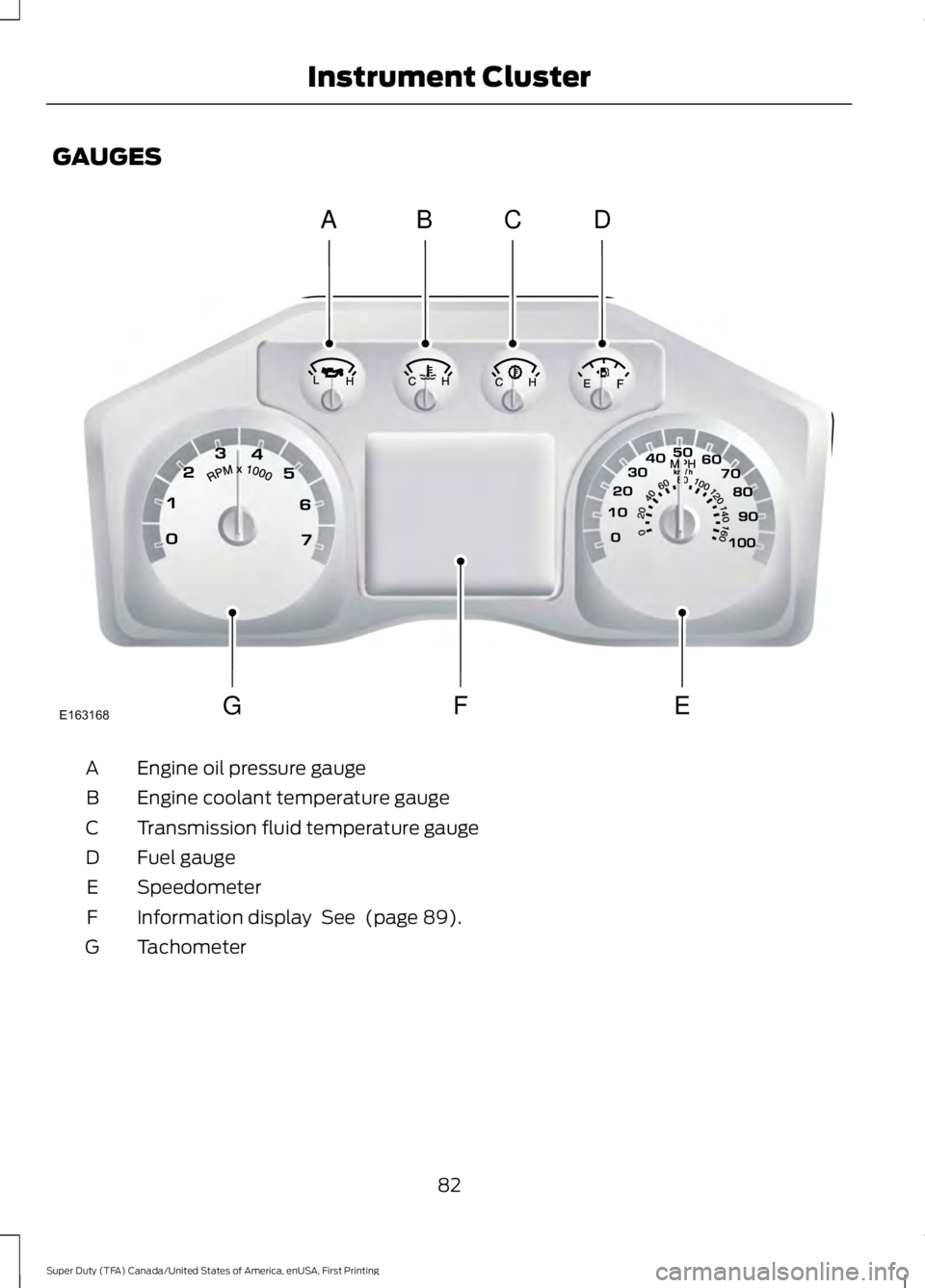
GAUGES
Engine oil pressure gauge
A
Engine coolant temperature gauge
B
Transmission fluid temperature gauge
C
Fuel gauge
D
Speedometer
E
Information display See (page 89).
F
Tachometer
G
82
Super Duty (TFA) Canada/United States of America, enUSA, First Printing Instrument ClusterABCD
GFEE163168
Page 86 of 507
Engine Oil Pressure Gauge
Indicates engine oil pressure. The needle
should stay in the normal operating range
(between L and H). If the needle falls
below the normal range, stop the vehicle,
turn off the engine and check the engine
oil level. Add oil if needed. If the oil level is
correct, have your vehicle checked by your
authorized dealer.
Engine Coolant Temperature
Gauge
WARNING
Never remove the coolant reservoir
cap while the engine is running or hot.
Indicates engine coolant temperature. At
normal operating temperature, the level
indicator will be in the normal range. If the
engine coolant temperature exceeds the
normal range, stop the vehicle as soon as
safely possible, switch off the engine and
let the engine cool.
Transmission Fluid Temperature
Gauge
Indicates transmission fluid temperature.
At normal operating temperature, the level
indicator will be in the normal range. If the
transmission fluid temperature exceeds
the normal range, stop the vehicle as soon
as safely possible and verify the airflow is
not restricted such as snow or debris
blocking airflow through the grill. Also,
higher than normal operating temperature
can be caused by special operation
conditions (i.e. snowplowing, towing or
off-road use). Refer to Special operating
conditions in the scheduled maintenance
information for instructions. Operating the transmission for extended periods of time
with the gauge in the higher than normal
area may cause internal transmission
damage. Altering the severity of the driving
conditions is recommended to lower the
transmission temperature into the normal
range. If the gauge continues to show high
temperatures, see your authorized dealer.
Fuel Gauge
Note:
The fuel gauge may vary slightly
when your vehicle is moving or on a gradient.
Switch the ignition on. The fuel gauge will
indicate approximately how much fuel is
left in the fuel tank. The arrow adjacent to
the fuel pump symbol indicates on which
side of your vehicle the fuel filler door is
located.
The needle should move toward F when
you refuel your vehicle. If the needle points
to E after adding fuel, this indicates your
vehicle needs service soon.
After refueling some variability in needle
position is normal:
• It may take a short time for the needle
to reach F after leaving the gas station.
This is normal and depends upon the
slope of pavement at the gas station.
• The fuel amount dispensed into the
tank is a little less or more than the
gauge indicated. This is normal and
depends upon the slope of pavement
at the gas station.
• If the gas station nozzle shuts off
before the tank is full, try a different
gas pump nozzle.
Low Fuel Reminder
A low fuel reminder triggers when the fuel
gauge needle is at 1/16th.
83
Super Duty (TFA) Canada/United States of America, enUSA, First Printing Instrument Cluster
Page 90 of 507
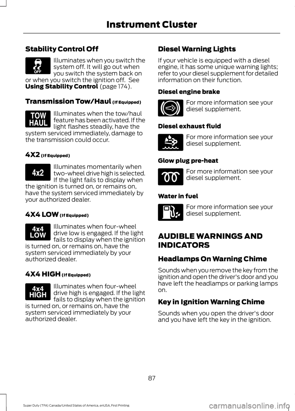
Stability Control Off
Illuminates when you switch the
system off. It will go out when
you switch the system back on
or when you switch the ignition off. See
Using Stability Control (page 174).
Transmission Tow/Haul
(If Equipped) Illuminates when the tow/haul
feature has been activated. If the
light flashes steadily, have the
system serviced immediately, damage to
the transmission could occur.
4X2
(If Equipped) Illuminates momentarily when
two-wheel drive high is selected.
If the light fails to display when
the ignition is turned on, or remains on,
have the system serviced immediately by
your authorized dealer.
4X4 LOW
(If Equipped) Illuminates when four-wheel
drive low is engaged. If the light
fails to display when the ignition
is turned on, or remains on, have the
system serviced immediately by your
authorized dealer.
4X4 HIGH
(If Equipped) Illuminates when four-wheel
drive high is engaged. If the light
fails to display when the ignition
is turned on, or remains on, have the
system serviced immediately by your
authorized dealer. Diesel Warning Lights
If your vehicle is equipped with a diesel
engine, it has some unique warning lights;
refer to your diesel supplement for detailed
information on their function.
Diesel engine brake For more information see your
diesel supplement.
Diesel exhaust fluid For more information see your
diesel supplement.
Glow plug pre-heat For more information see your
diesel supplement.
Water in fuel For more information see your
diesel supplement.
AUDIBLE WARNINGS AND
INDICATORS
Headlamps On Warning Chime
Sounds when you remove the key from the
ignition and open the driver's door and you
have left the headlamps or parking lamps
on.
Key in Ignition Warning Chime
Sounds when you open the driver's door
and you have left the key in the ignition.
87
Super Duty (TFA) Canada/United States of America, enUSA, First Printing Instrument Cluster E161509 E163173 E163174 E163175 E171217 E163176
Page 159 of 507
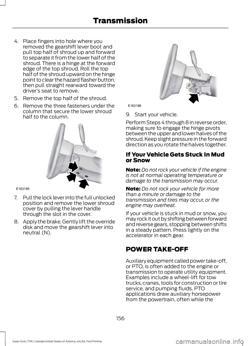
4. Place fingers into hole where you
removed the gearshift lever boot and
pull top half of shroud up and forward
to separate it from the lower half of the
shroud. There is a hinge at the forward
edge of the top shroud. Roll the top
half of the shroud upward on the hinge
point to clear the hazard flasher button,
then pull straight rearward toward the
driver ’s seat to remove.
5. Remove the top half of the shroud.
6. Remove the three fasteners under the column that secure the lower shroud
half to the column. 7.
Pull the lock lever into the full unlocked
position and remove the lower shroud
cover by pulling the lever handle
through the slot in the cover.
8. Apply the brake. Gently lift the override
disk and move the gearshift lever into
neutral (N). 9. Start your vehicle.
Perform Steps 4 through 8 in reverse order,
making sure to engage the hinge pivots
between the upper and lower halves of the
shroud. Keep slight pressure in the forward
direction as you rotate the halves together.
If Your Vehicle Gets Stuck In Mud
or Snow
Note:
Do not rock your vehicle if the engine
is not at normal operating temperature or
damage to the transmission may occur.
Note: Do not rock your vehicle for more
than a minute or damage to the
transmission and tires may occur, or the
engine may overheat.
If your vehicle is stuck in mud or snow, you
may rock it out by shifting between forward
and reverse gears, stopping between shifts
in a steady pattern. Press lightly on the
accelerator in each gear.
POWER TAKE-OFF
Auxiliary equipment called power take-off,
or PTO, is often added to the engine or
transmission to operate utility equipment.
Examples include a wheel-lift for tow
trucks, cranes, tools for construction or tire
service, and pumping fluids. PTO
applications draw auxiliary horsepower
from the powertrain, often while the
156
Super Duty (TFA) Canada/United States of America, enUSA, First Printing TransmissionE163185 E163186
Page 213 of 507
•
The tire air pressures recommended
for general driving are on the vehicle ’s
Safety Certification Label. The
maximum cold inflation pressure for
the tire and associated load rating is
on the tire sidewall. Tire air pressure
may require re-adjustment within these
pressure limits to accommodate the
additional weight of the snowplow
installation.
• Federal and some local regulations
require additional exterior lamps for
snowplow-equipped vehicles. Consult
your authorized dealer for additional
information.
Operating the Vehicle with the
Snowplow Attached
Note: Do not use your vehicle for snow
removal until you have driven at least
500 mi (800 km).
Ford recommends vehicle speed does not
exceed
45 mph (72 km/h) when
snowplowing.
The attached snowplow blade restricts
airflow to the radiator, and may cause the
engine to run at a higher temperature:
Attention to engine temperature is
especially important when outside
temperatures are above freezing. Angle
the blade to maximize airflow to the
radiator and monitor engine temperature
to determine whether a left or right angle
provides the best performance.
Follow the severe duty schedule in your
Scheduled Maintenance information for
engine oil and transmission fluid change
intervals. Snowplowing with your Airbag
Equipped Vehicle WARNINGS
Do not attempt to service, repair, or
modify the airbag supplemental
restraint system (SRS) or its fuses.
Contact an authorized dealer. Additional equipment such as
snowplow equipment may affect the
performance of the airbag sensors
increasing the risk of injury. Please refer to
the Body Builders Layout Book for
instructions about the appropriate
installation of additional equipment. All occupants of the vehicle,
including the driver, should always
properly wear their safety belts, even
when provided with an airbag
supplemental restraint system (SRS). Your vehicle is equipped with a driver and
passenger airbag supplemental restraint
system. The supplemental restraint system
will activate in certain frontal and offset
frontal collisions when the vehicle sustains
sufficient frontal deceleration.
Careless or high speed driving while
plowing snow that results in sufficient
vehicle decelerations can deploy the
airbag. Such driving also increases the risk
of accidents
Never remove or defeat the tripping
mechanisms designed into the snow
removal equipment by its manufacturer.
Doing so may cause damage to the vehicle
and the snow removal equipment as well
as possible airbag deployment.
Engine temperature while plowing
When driving with a plow, your engine may
run at a higher temperature than normal
because the attached snowplow blade will
restrict airflow to the radiator.
210
Super Duty (TFA) Canada/United States of America, enUSA, First Printing Driving Hints
Page 236 of 507
2. Go to the front of the vehicle and
locate the secondary release lever,
which is located under the front of the
hood, to your right of the center of the
vehicle (driver's side), toward the
headlight.
3. Release the hood latch by pushing the secondary release lever to your left,
toward the center of the vehicle.
4. Raise the hood. 5.
To close the hood, lower the hood and
allow it to drop the last 8 to 11 inches
(20 to 30 centimeters).
Note: Make sure that the hood is closed
properly.
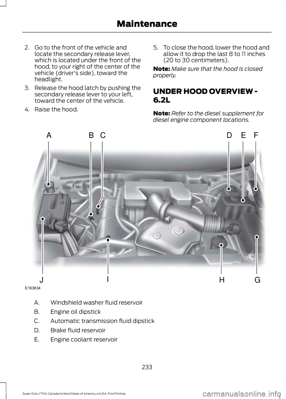
UNDER HOOD OVERVIEW -
6.2L
Note: Refer to the diesel supplement for
diesel engine component locations. Windshield washer fluid reservoir
A.
Engine oil dipstick
B.
Automatic transmission fluid dipstick
C.
Brake fluid reservoir
D.
Engine coolant reservoir
E.
233
Super Duty (TFA) Canada/United States of America, enUSA, First Printing MaintenanceE163634
ADFEBC
GHIJ
Page 237 of 507
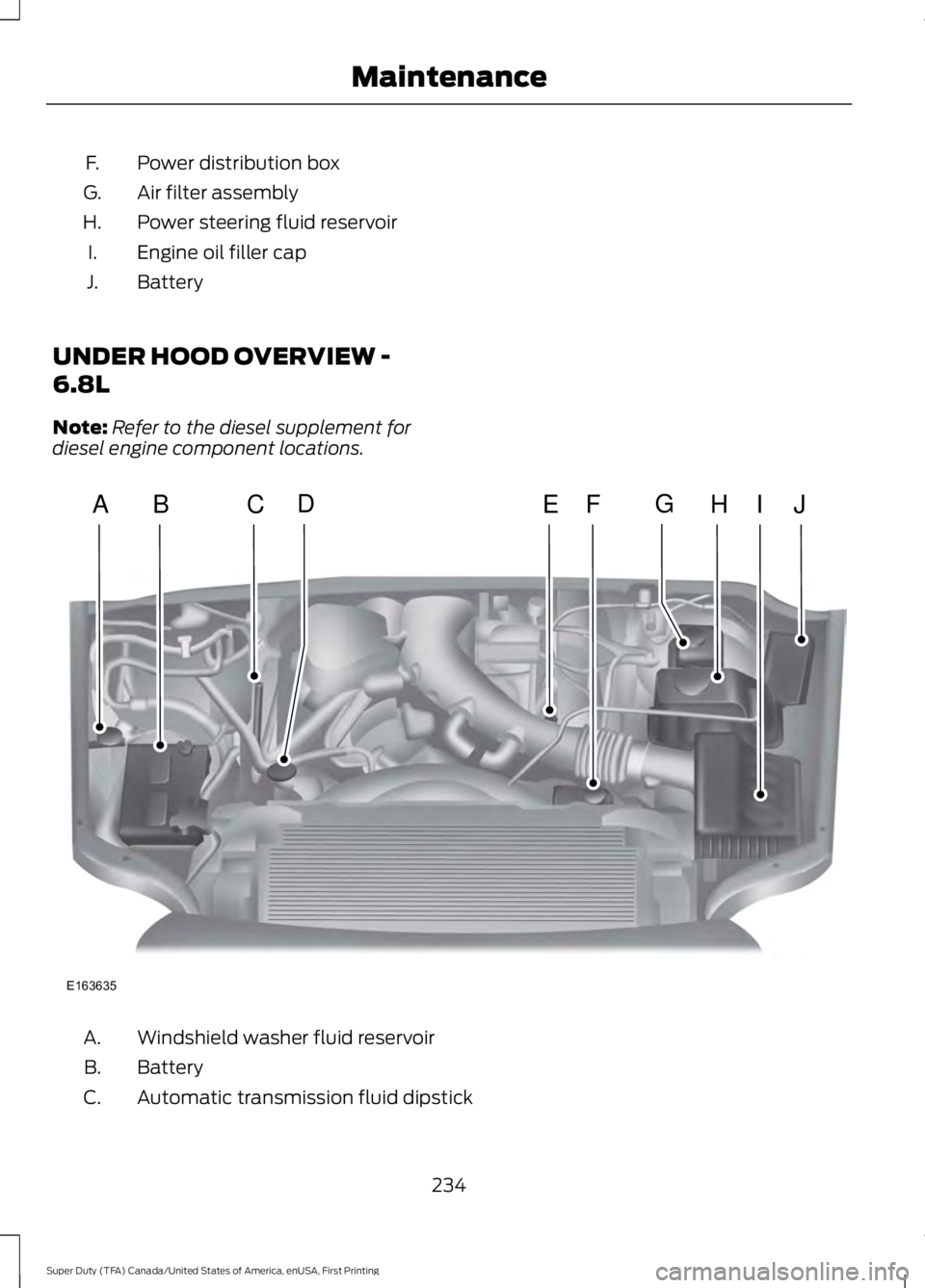
Power distribution box
F.
Air filter assembly
G.
Power steering fluid reservoir
H.
Engine oil filler cap
I.
Battery
J.
UNDER HOOD OVERVIEW -
6.8L
Note: Refer to the diesel supplement for
diesel engine component locations. Windshield washer fluid reservoir
A.
Battery
B.
Automatic transmission fluid dipstick
C.
234
Super Duty (TFA) Canada/United States of America, enUSA, First Printing MaintenanceE163635
ABCEHIJFDG
Page 243 of 507
Engine Fluid Temperature
Management (If Equipped)
WARNINGS
To reduce the risk of collision and
injury, be prepared that the vehicle
speed may reduce and the vehicle
may not be able to accelerate with full
power until the fluid temperatures reduce. Never remove the coolant reservoir
cap while the engine is running or hot.
Your vehicle has been designed to pull a
trailer, but because of the added load, the
vehicle
’s engine may temporarily reach
higher temperatures during severe
operating conditions such as ascending a
long or steep grade while pulling a trailer
in hot ambient temperatures.
At this time, you may notice your engine
coolant temperature gauge needle move
toward the H and the POWER REDUCED
TO LOWER TEMP message may appear
in the information display.
You may notice a reduction in the vehicle ’s
speed caused by reduced engine power.
In order to manage the engine fluid
temperatures, your vehicle may enter this
mode if certain high-temperature and
high-load conditions take place. The
amount of speed reduction will depend on
the vehicle loading, towing, grade, ambient
temperature, and other factors. If this
occurs, there is no need to pull off the road.
The vehicle can continue to be driven while
this message is active.
The air conditioning may turn on and off
during severe operating conditions to
protect the engine from overheating. When
the engine coolant temperature decreases
to a more normal operating temperature,
the air conditioning will turn on once again. If the engine coolant temperature gauge
moves fully into the red (hot) area, or if the
coolant temperature warning or service
engine soon messages appear in your
information display:
1. Stop your vehicle as soon as safely
possible and shift the transmission into
park (P).
2. Leave the engine running until the coolant temperature gauge needle
moves away from the H range. After
several minutes, if this does not
happen, follow the remaining steps.
3. Switch the engine off and wait for it to
cool before checking the coolant level.
4. If the coolant level is normal, you may restart your engine and continue on.
5. If the coolant is low, add coolant, restart the engine and take your vehicle
to an authorized dealer. See Adding
engine coolant in this chapter for more
information. Refer to fail-safe cooling
for additional information.
AUTOMATIC TRANSMISSION
FLUID CHECK
Have an authorized dealer check and
change the transmission fluid and filter at
the correct service interval. See
Scheduled Maintenance (page 453).
Do not use supplemental transmission
fluid additives, treatments or cleaning
agents. The use of these materials may
affect transmission operation and result
in damage to internal transmission
components.
240
Super Duty (TFA) Canada/United States of America, enUSA, First Printing Maintenance
Page 244 of 507
Checking Automatic Transmission
Fluid
For scheduled intervals of the fluid checks
and changes, See Scheduled
Maintenance (page 453). Your
transmission does not consume fluid.
However, the fluid level should be checked
if the transmission is not working properly,
i.e., if the transmission slips or shifts slowly
or if you notice some sign of fluid leakage.
Automatic transmission fluid expands
when warmed. To obtain an accurate fluid
check, drive the vehicle until it is at normal
operating temperature (approximately
19 mi (30 km)
). Verify that the
transmission fluid temperature gauge,
located on the instrument cluster, is within
normal range.
1. Drive the vehicle
19 (30 km)until it
reaches normal operating temperature.
2. Park the vehicle on a level surface and
engage the parking brake.
3. With the engine running, parking brake
engaged and your foot on the brake
pedal, move the gearshift lever through
all of the gear ranges. Allow sufficient
time for each gear to engage.
4. Latch the gearshift lever in P and leave
the engine running.
5. Remove the dipstick, wiping it clean with a clean, dry lint free rag. If
necessary, refer to the Under Hood
Overview in this chapter for the
location of the dipstick.
6. Install the dipstick making sure it is fully
seated in the filler tube.
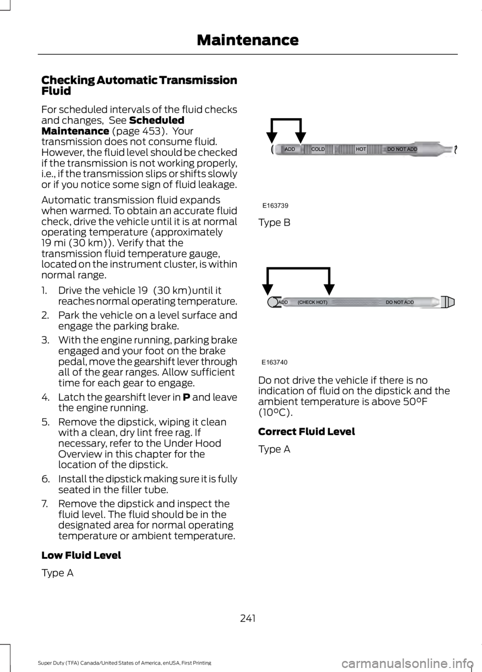
7. Remove the dipstick and inspect the fluid level. The fluid should be in the
designated area for normal operating
temperature or ambient temperature.
Low Fluid Level
Type A Type B
Do not drive the vehicle if there is no
indication of fluid on the dipstick and the
ambient temperature is above
50°F
(10°C).
Correct Fluid Level
Type A
241
Super Duty (TFA) Canada/United States of America, enUSA, First Printing MaintenanceE163739 E163740