glove box FORD F250 SUPER DUTY 2006 Owners Manual
[x] Cancel search | Manufacturer: FORD, Model Year: 2006, Model line: F250 SUPER DUTY, Model: FORD F250 SUPER DUTY 2006Pages: 312, PDF Size: 5.15 MB
Page 64 of 312

UPFITTER CONTROLS (IF EQUIPPED)
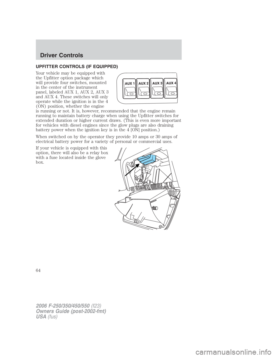
Your vehicle may be equipped with
the Upfitter option package which
will provide four switches, mounted
in the center of the instrument
panel, labeled AUX 1, AUX 2, AUX 3
and AUX 4. These switches will only
operate while the ignition is in the 4
(ON) position, whether the engine
is running or not. It is, however, recommended that the engine remain
running to maintain battery charge when using the Upfitter switches for
extended duration or higher current draws. (This is even more important
for vehicles with diesel engines since the glow plugs are also draining
battery power when the ignition key is in the 4 [ON] position.)
When switched on by the operator they provide 10 amps or 30 amps of
electrical battery power for a variety of personal or commercial uses.
If your vehicle is equipped with this
option, there will also be a relay box
with a fuse located inside the glove
box.
2006 F-250/350/450/550 (f23)
Owners Guide (post-2002-fmt)
USA (fus)Driver Controls
64
Page 65 of 312

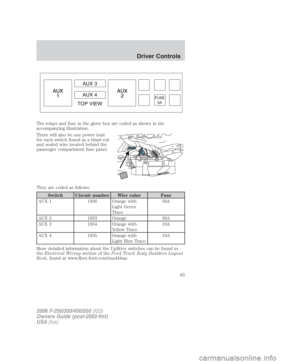
The relays and fuse in the glove box are coded as shown in the
accompanying illustration.
There will also be one power lead
for each switch found as a blunt-cut
and sealed wire located behind the
passenger compartment fuse panel.
They are coded as follows:
Switch Circuit number Wire color Fuse
AUX 1 1936 Orange with
Light Green
Trace 30A
AUX 2 1933 Orange 30A
AUX 3 1934 Orange with
Yellow Trace 10A
AUX 4 1935 Orange with
Light Blue Trace 10A
More detailed information about the Upfitter switches can be found in
the Electrical Wiring section of the Ford Truck Body Builders Layout
Book , found at www.fleet.ford.com/truckbbas.
2006 F-250/350/450/550 (f23)
Owners Guide (post-2002-fmt)
USA (fus) Driver Controls
65
Page 86 of 312

Illuminated entry
The interior lamps illuminate when the remote entry system is used to
unlock the door(s).
The illuminated entry system will turn off the interior lights if:
• the ignition switch is turned to the 4 (ON) position, or
• the remote transmitter lock control is pressed, or
• the 7 • 8 and the 9 • 0 controls on the keyless entry keypad are
pressed, or
• after 25 seconds of illumination.
The dome lamp control (if equipped) must not be set to the off position
for the illuminated entry system to operate.
The inside lights will not turn off if:
• they have been turned on with the dimmer control, or
• any door is open.
The battery saver will shut off the interior lamps 30 minutes after the
ignition has been turned to the 3 (OFF) position, 10 minutes after if the
dome lamp is off, and 30 minutes after if the dome lamp switch is left
on.
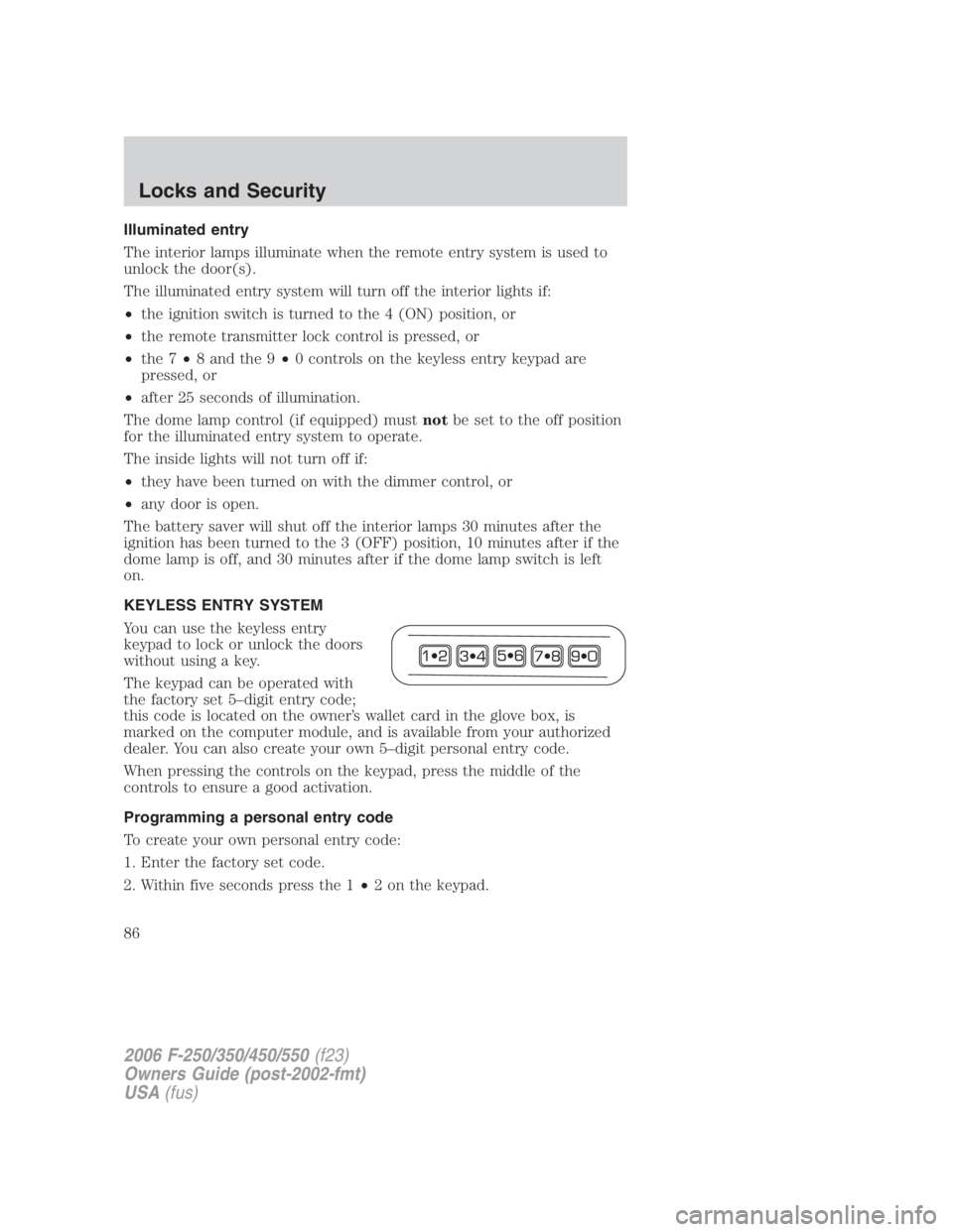
KEYLESS ENTRY SYSTEM
You can use the keyless entry
keypad to lock or unlock the doors
without using a key.
The keypad can be operated with
the factory set 5–digit entry code;
this code is located on the owner’s wallet card in the glove box, is
marked on the computer module, and is available from your authorized
dealer. You can also create your own 5–digit personal entry code.
When pressing the controls on the keypad, press the middle of the
controls to ensure a good activation.
Programming a personal entry code
To create your own personal entry code:
1. Enter the factory set code.
2. Within five seconds press the 1 • 2 on the keypad.
2006 F-250/350/450/550 (f23)
Owners Guide (post-2002-fmt)
USA (fus)Locks and Security
86
Page 217 of 312

Tool Location
Jack handle and lug
wrench Regular cab: Fastened to floor behind front seat
Super Cab: Fastened to floor under rear seat
Crew Cab: Fastened to floor behind rear seat
Key, spare tire lock In the glove box
Removing the spare tire (with spare tire carrier only)
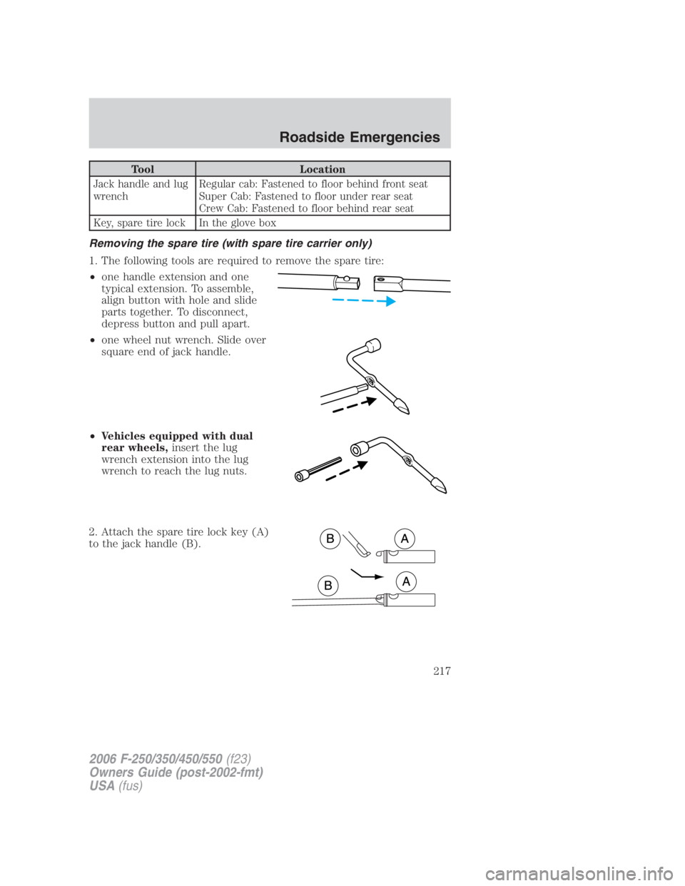
1. The following tools are required to remove the spare tire:
• one handle extension and one
typical extension. To assemble,
align button with hole and slide
parts together. To disconnect,
depress button and pull apart.
• one wheel nut wrench. Slide over
square end of jack handle.
• Vehicles equipped with dual
rear wheels, insert the lug
wrench extension into the lug
wrench to reach the lug nuts.
2. Attach the spare tire lock key (A)
to the jack handle (B).
2006 F-250/350/450/550 (f23)
Owners Guide (post-2002-fmt)
USA (fus) Roadside Emergencies
217