fuel FORD F350 2008 Owner's Guide
[x] Cancel search | Manufacturer: FORD, Model Year: 2008, Model line: F350, Model: FORD F350 2008Pages: 400, PDF Size: 3.83 MB
Page 290 of 400
VEHICLE USED AS A STATIONARY POWER SOURCE
Auxiliary equipment called power take-off, or PTO, is often added to the
engine or transmission to operate utility equipment. Examples include a
wheel-lift for tow trucks, cranes, tools for construction or tire service,
and pumping fluids. PTO applications draw auxiliary horsepower from
the powertrain, often while the vehicle is stationary. In this condition,
there is limited cooling air flow through the radiator and around the
vehicle that normally occurs when a vehicle is moving. The aftermarket
PTO system installer, having the most knowledge of the final application,
is responsible for determining whether additional chassis heat protection
or powertrain cooling is required, and alerting the user to the safe and
proper operation.
Ford Super Duty Vehicles are qualified for use as a stationary power
source, within limits detailed in theFord Truck Body Builders Layout
Book,found at www.fleet.ford.com/truckbbas, and through the Ford
Truck Body Builders Advisory Service.
Gas engine vehicles are qualified for up to 10 minutes of continuous
operation as a stationary power source, due to the potential for the
normal venting of fuel vapors. For stationary PTO operation of extended
duration (beyond 10 minutes), diesel engine is recommended. Further
consult your aftermarket PTO installer, since the duration of operation
limit for the aftermarket PTO may be less than the vehicle is capable of.
DRIVING THROUGH WATER
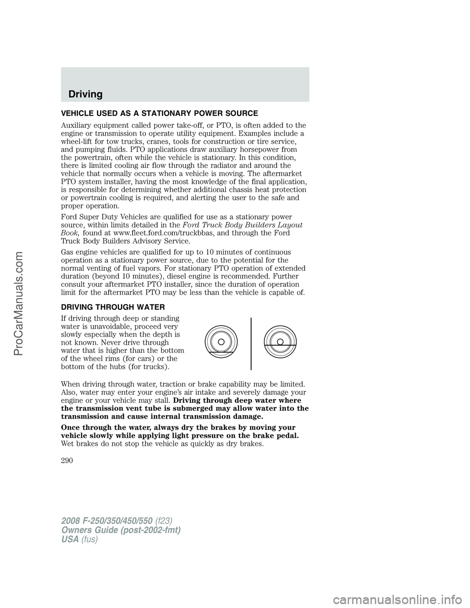
If driving through deep or standing
water is unavoidable, proceed very
slowly especially when the depth is
not known. Never drive through
water that is higher than the bottom
of the wheel rims (for cars) or the
bottom of the hubs (for trucks).
When driving through water, traction or brake capability may be limited.
Also, water may enter your engine’s air intake and severely damage your
engine or your vehicle may stall.Driving through deep water where
the transmission vent tube is submerged may allow water into the
transmission and cause internal transmission damage.
Once through the water, always dry the brakes by moving your
vehicle slowly while applying light pressure on the brake pedal.
Wet brakes do not stop the vehicle as quickly as dry brakes.
2008 F-250/350/450/550(f23)
Owners Guide (post-2002-fmt)
USA(fus)
Driving
290
ProCarManuals.com
Page 294 of 400
ROADSIDE ASSISTANCE
Getting roadside assistance
To fully assist you should you have a vehicle concern, Ford Motor
Company offers a complimentary roadside assistance program. This
program is separate from the New Vehicle Limited Warranty. The service
is available:
•24–hours, seven days a week
•for the coverage period listed on the Roadside Assistance Card
included in your Owner Guide portfolio.
Roadside assistance will cover:
•a flat tire change with a good spare (except vehicles that have been
supplied with a tire inflation kit)
•battery jump start
•lock-out assistance (key replacement cost is the customer’s
responsibility)
•fuel delivery – Independent Service Contractors, if not prohibited by
state, local or municipal law shall deliver up to 2.0 gallons (7.5L) of
gasoline or 5 gallons (18.9L) of diesel fuel to a disabled vehicle. Fuel
delivery service is limited to two no-charge occurrences within a
12-month period.
•winch out – available within 100 feet (30.5 meters) of a paved or
county maintained road, no recoveries.
•towing – Ford/Mercury/Lincoln eligible vehicle towed to an authorized
dealer within 35 miles (56.3 km) of the disablement location or to the
nearest authorized dealer. If a member requests to be towed to an
authorized dealer more than 35 miles (56.3 km) from the disablement
location, the member shall be responsible for any mileage costs in
excess of 35 miles (56.3 km).
Trailers shall be covered up to $200 if the disabled eligible vehicle
requires service at the nearest authorized dealer. If the trailer is disabled,
but the towing vehicle is operational, the trailer does not qualify for any
roadside services.
2008 F-250/350/450/550(f23)
Owners Guide (post-2002-fmt)
USA(fus)
Roadside Emergencies
294
ProCarManuals.com
Page 295 of 400
Canadian customers refer to your Customer Information Guide
for information on:
•coverage period
•exact fuel amounts
•towing of your disabled vehicle
•emergency travel expense reimbursement
•travel planning benefits
Using roadside assistance
Complete the roadside assistance identification card and place it in your
wallet for quick reference. In the United States, this card is found in the
Owner Guide portfolio in the glove compartment. In Canada, the card is
found in theCustomer Information Guidein the glove compartment.
U.S. Ford, Mercury and Lincoln vehicle customers who require Roadside
Assistance, call 1-800-241-3673.
Canadian customers who require roadside assistance, call
1-800-665-2006.
If you need to arrange roadside assistance for yourself, Ford Motor
Company will reimburse a reasonable amount for towing to the nearest
dealership within 35 miles. To obtain reimbursement information, U.S.
Ford, Mercury and Lincoln vehicle customers call 1-800-241-3673.
Customers will be asked to submit their original receipts.
Canadian customers who need to obtain reimbursement information, call
1–800–665–2006.
Roadside coverage beyond basic warranty
In the United States, you may purchase additional roadside assistance
coverage beyond this period through the Ford Auto Club by contacting
your authorized dealer or by calling 1–800–FORD–CLUB.
Similarly in Canada, for uninterrupted Roadside Assistance coverage, you
may purchase extended coverage prior to your Basic Warranty’s Roadside
Assistance expiring. For more information and enrollment, contact
1–877–294–2582 or visit our website at www.ford.ca.
2008 F-250/350/450/550(f23)
Owners Guide (post-2002-fmt)
USA(fus)
Roadside Emergencies
295
ProCarManuals.com
Page 296 of 400
HAZARD FLASHER
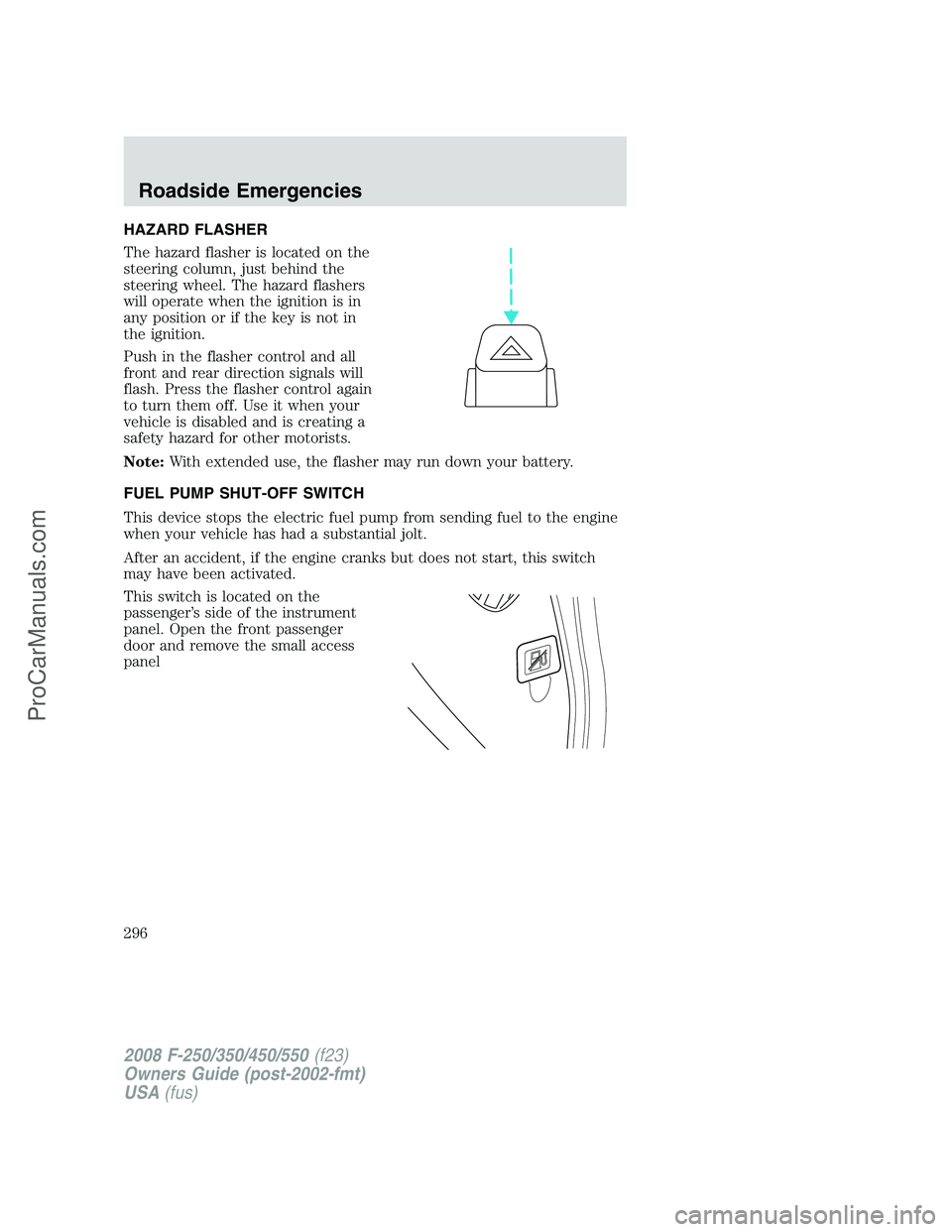
The hazard flasher is located on the
steering column, just behind the
steering wheel. The hazard flashers
will operate when the ignition is in
any position or if the key is not in
the ignition.
Push in the flasher control and all
front and rear direction signals will
flash. Press the flasher control again
to turn them off. Use it when your
vehicle is disabled and is creating a
safety hazard for other motorists.
Note:With extended use, the flasher may run down your battery.
FUEL PUMP SHUT-OFF SWITCH
This device stops the electric fuel pump from sending fuel to the engine
when your vehicle has had a substantial jolt.
After an accident, if the engine cranks but does not start, this switch
may have been activated.
This switch is located on the
passenger’s side of the instrument
panel. Open the front passenger
door and remove the small access
panel
2008 F-250/350/450/550(f23)
Owners Guide (post-2002-fmt)
USA(fus)
Roadside Emergencies
296
ProCarManuals.com
Page 297 of 400
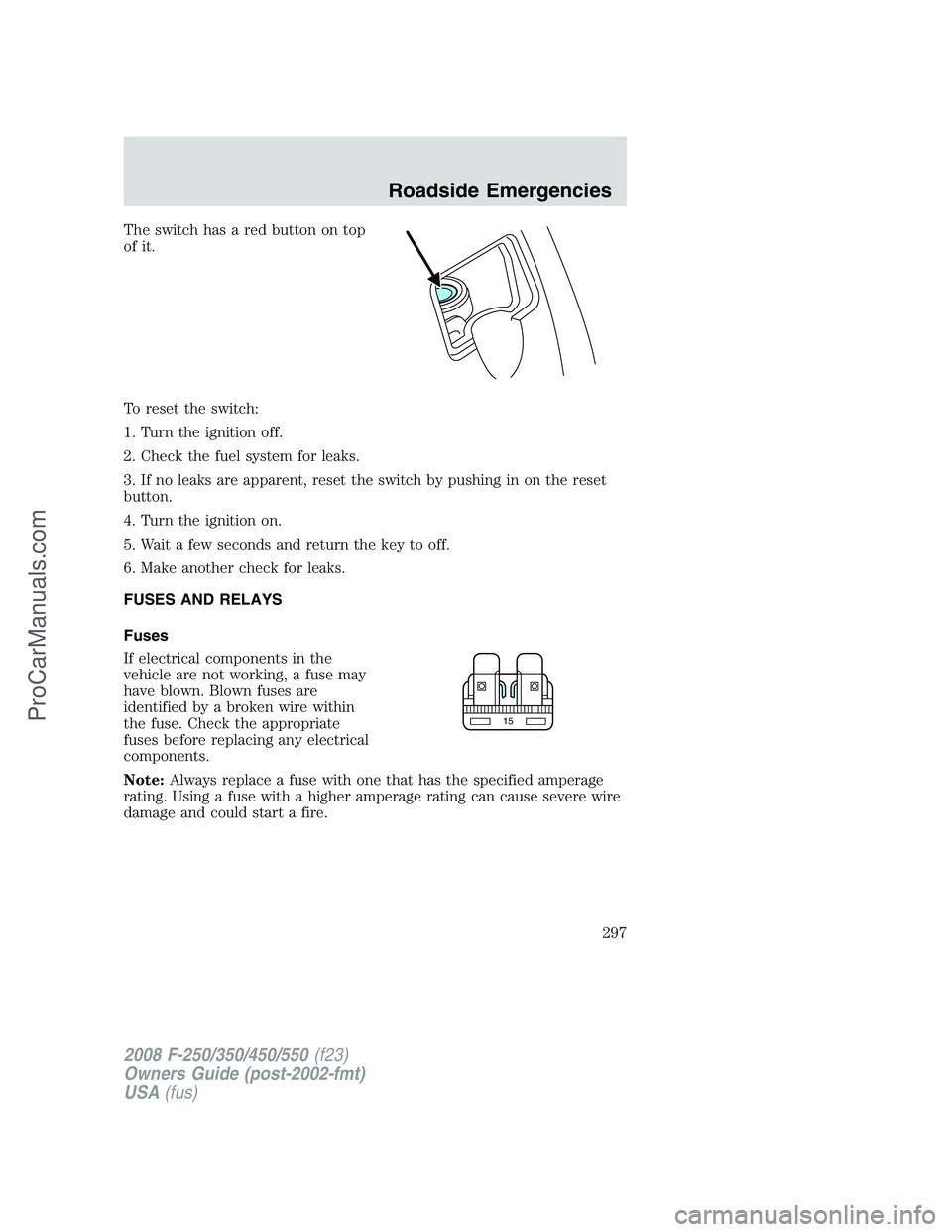
The switch has a red button on top
of it.
To reset the switch:
1. Turn the ignition off.
2. Check the fuel system for leaks.
3. If no leaks are apparent, reset the switch by pushing in on the reset
button.
4. Turn the ignition on.
5. Wait a few seconds and return the key to off.
6. Make another check for leaks.
FUSES AND RELAYS
Fuses
If electrical components in the
vehicle are not working, a fuse may
have blown. Blown fuses are
identified by a broken wire within
the fuse. Check the appropriate
fuses before replacing any electrical
components.
Note:Always replace a fuse with one that has the specified amperage
rating. Using a fuse with a higher amperage rating can cause severe wire
damage and could start a fire.
15
2008 F-250/350/450/550(f23)
Owners Guide (post-2002-fmt)
USA(fus)
Roadside Emergencies
297
ProCarManuals.com
Page 302 of 400
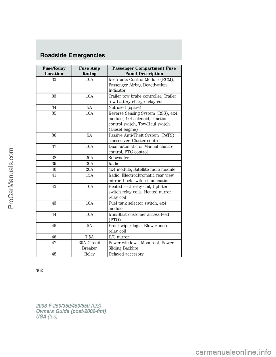
Fuse/Relay
LocationFuse Amp
RatingPassenger Compartment Fuse
Panel Description
32 10A Restraints Control Module (RCM),
Passenger Airbag Deactivation
Indicator
33 10A Trailer tow brake controller, Trailer
tow battery charge relay coil
34 5A Not used (spare)
35 10A Reverse Sensing System (RSS), 4x4
module, 4x4 solenoid, Traction
control switch, Tow/Haul switch
(Diesel engine)
36 5A Passive Anti-Theft System (PATS)
transceiver, Cluster control
37 10A Dual automatic or Manual climate
control, PTC control
38 20A Subwoofer
39 20A Radio
40 20A 4x4 module, Satellite radio module
41 15A Radio, Electrochromatic rear view
mirror, Lock switch illumination
42 10A Heated seat relay coil, Upfitter
switch relay coils, Heated mirror
relay coil
43 10A Fuel tank selector switch, 4x4
module
44 10A Run/Start customer access feed
(PTO)
45 5A Front wiper logic, Blower motor
relay coil
46 7.5A E/C mirror
47 30A Circuit
BreakerPower windows, Moonroof, Power
Sliding Backlite
48 Relay Delayed accessory
2008 F-250/350/450/550(f23)
Owners Guide (post-2002-fmt)
USA(fus)
Roadside Emergencies
302
ProCarManuals.com
Page 304 of 400

Fuse/Relay
LocationFuse Amp
RatingPower Distribution Box
Description
6 40A* ABS module (Pump)
7 30A* Upfitter auxiliary switch #1
8 30A* Upfitter auxiliary switch #2
9 40A* ABS module (Coil)
10 20A* Cigar lighter
11 20A* Instrument panel power point
12 15A** Brake On/Off (BOO) relay feed
13 5A ** Brake switch, Brake switch relay
coil, SJB module, 4x4 module
14 — Not used
15 — Not used
16 Relay A/C clutch
17 Relay Not used
18 Relay Fuel Pump Driver Module (FPDM),
Fuel injectors (Gasoline engines),
Diesel Fuel Control Module (DFCM)
(Diesel engine)
19 Relay Back-up lamps, Reverse Sensing
System (RSS), Engine compartment
fuse 63
20 Relay Trailer stop/turn (Left)
21 Relay Trailer stop/turn (Right)
22 Relay Stop lamps, Center High-Mounted
Stop Lamp (CHMSL), TBC,
Customer access
23 15A** Heater mirror
24 40A* Blower motor relay
25 — Not used
26 30A* ESOF relay lo-hi
27 50A* Glow Plug Control Module (GPCM)
#1 (Diesel engine only)
28 20A* Heated mirror relay
2008 F-250/350/450/550(f23)
Owners Guide (post-2002-fmt)
USA(fus)
Roadside Emergencies
304
ProCarManuals.com
Page 305 of 400
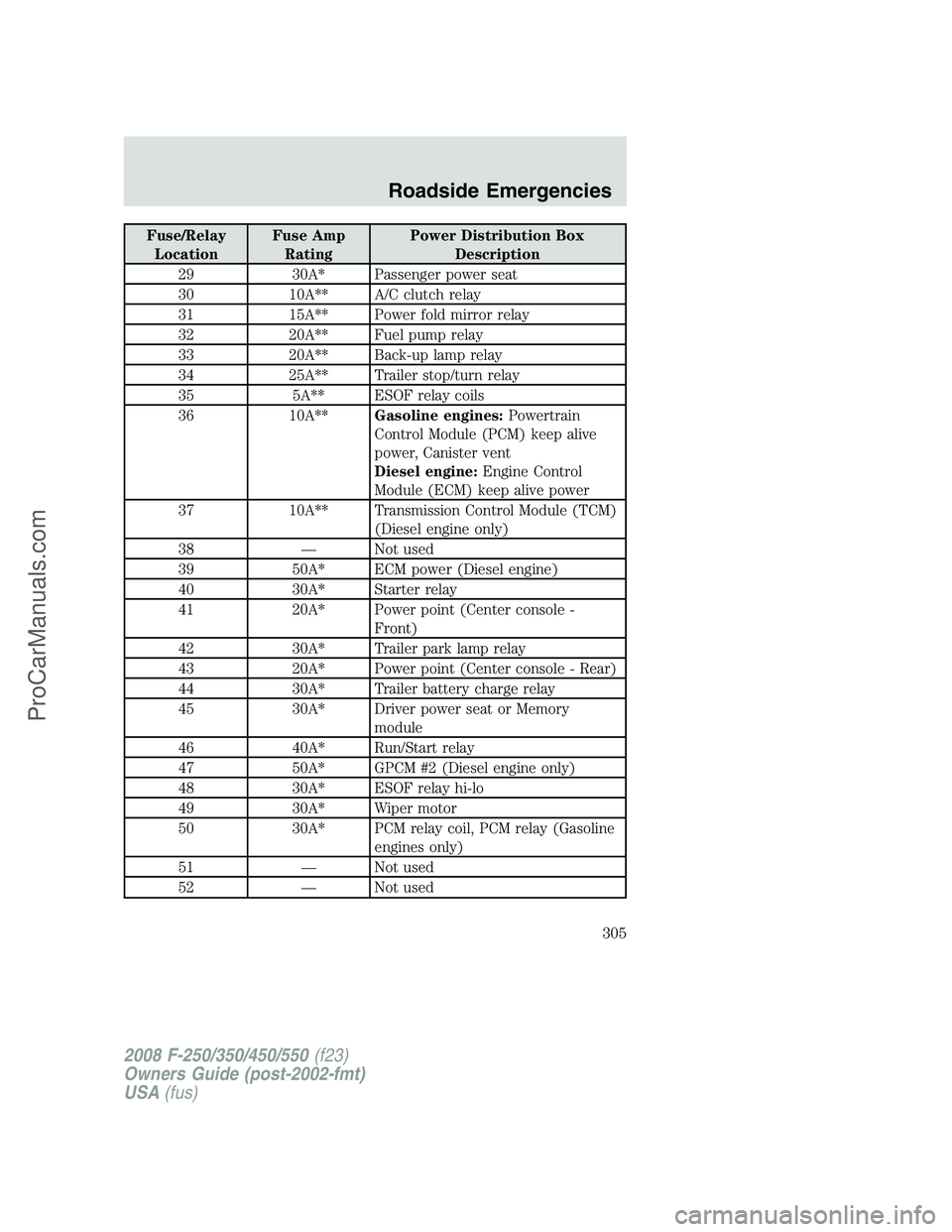
Fuse/Relay
LocationFuse Amp
RatingPower Distribution Box
Description
29 30A* Passenger power seat
30 10A** A/C clutch relay
31 15A** Power fold mirror relay
32 20A** Fuel pump relay
33 20A** Back-up lamp relay
34 25A** Trailer stop/turn relay
35 5A** ESOF relay coils
36 10A**Gasoline engines:Powertrain
Control Module (PCM) keep alive
power, Canister vent
Diesel engine:Engine Control
Module (ECM) keep alive power
37 10A** Transmission Control Module (TCM)
(Diesel engine only)
38 — Not used
39 50A* ECM power (Diesel engine)
40 30A* Starter relay
41 20A* Power point (Center console -
Front)
42 30A* Trailer park lamp relay
43 20A* Power point (Center console - Rear)
44 30A* Trailer battery charge relay
45 30A* Driver power seat or Memory
module
46 40A* Run/Start relay
47 50A* GPCM #2 (Diesel engine only)
48 30A* ESOF relay hi-lo
49 30A* Wiper motor
50 30A* PCM relay coil, PCM relay (Gasoline
engines only)
51 — Not used
52 — Not used
2008 F-250/350/450/550(f23)
Owners Guide (post-2002-fmt)
USA(fus)
Roadside Emergencies
305
ProCarManuals.com
Page 306 of 400
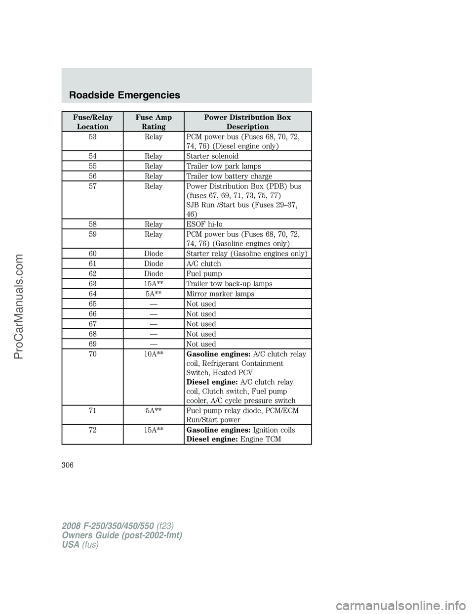
Fuse/Relay
LocationFuse Amp
RatingPower Distribution Box
Description
53 Relay PCM power bus (Fuses 68, 70, 72,
74, 76) (Diesel engine only)
54 Relay Starter solenoid
55 Relay Trailer tow park lamps
56 Relay Trailer tow battery charge
57 Relay Power Distribution Box (PDB) bus
(fuses 67, 69, 71, 73, 75, 77)
SJB Run /Start bus (Fuses 29–37,
46)
58 Relay ESOF hi-lo
59 Relay PCM power bus (Fuses 68, 70, 72,
74, 76) (Gasoline engines only)
60 Diode Starter relay (Gasoline engines only)
61 Diode A/C clutch
62 Diode Fuel pump
63 15A** Trailer tow back-up lamps
64 5A** Mirror marker lamps
65 — Not used
66 — Not used
67 — Not used
68 — Not used
69 — Not used
70 10A**Gasoline engines:A/C clutch relay
coil, Refrigerant Containment
Switch, Heated PCV
Diesel engine:A/C clutch relay
coil, Clutch switch, Fuel pump
cooler, A/C cycle pressure switch
71 5A** Fuel pump relay diode, PCM/ECM
Run/Start power
72 15A**Gasoline engines:Ignition coils
Diesel engine:Engine TCM
2008 F-250/350/450/550(f23)
Owners Guide (post-2002-fmt)
USA(fus)
Roadside Emergencies
306
ProCarManuals.com
Page 324 of 400
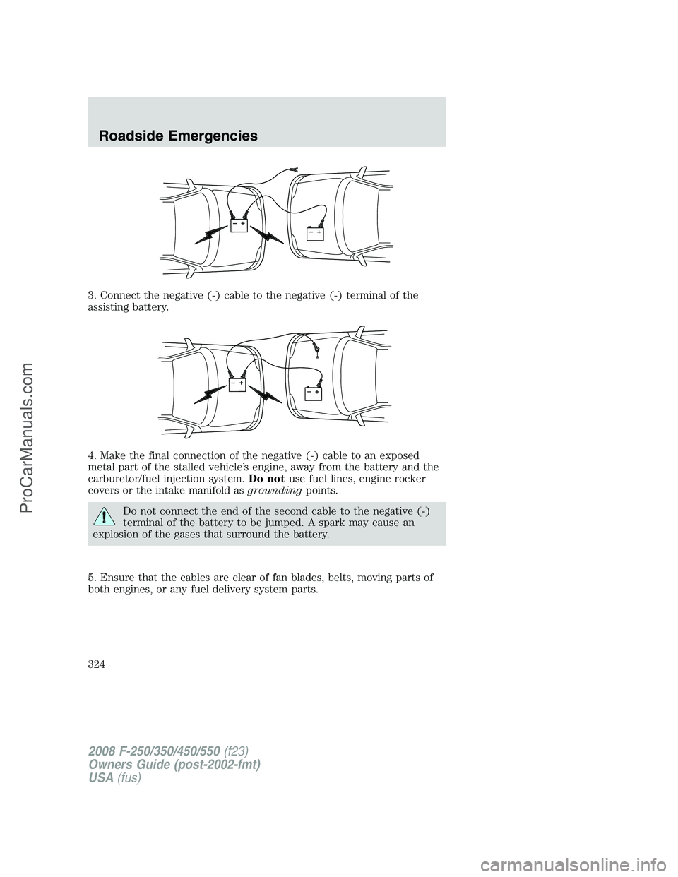
3. Connect the negative (-) cable to the negative (-) terminal of the
assisting battery.
4. Make the final connection of the negative (-) cable to an exposed
metal part of the stalled vehicle’s engine, away from the battery and the
carburetor/fuel injection system.Do notuse fuel lines, engine rocker
covers or the intake manifold asgroundingpoints.
Do not connect the end of the second cable to the negative (-)
terminal of the battery to be jumped. A spark may cause an
explosion of the gases that surround the battery.
5. Ensure that the cables are clear of fan blades, belts, moving parts of
both engines, or any fuel delivery system parts.
+–+–
+–+–
2008 F-250/350/450/550(f23)
Owners Guide (post-2002-fmt)
USA(fus)
Roadside Emergencies
324
ProCarManuals.com