display FORD F350 2008 Repair Manual
[x] Cancel search | Manufacturer: FORD, Model Year: 2008, Model line: F350, Model: FORD F350 2008Pages: 400, PDF Size: 3.83 MB
Page 139 of 400
DRAIN WATER SEPARATOR (Diesel engine only).Displayed when
the water separator has reached a predetermined capacity and needs to
be drained. Refer to your6.0 and 6.4 Liter Power Stroke Direct
Injection Turbo Diesel Owner’s Guide Supplementfor more
information.
STOP SAFELY NOW (Diesel engine only).Displayed when the
vehicle exhaust system temperature exceeds intended operating range. If
this warning occurs, the engine power is reduced and the engine will
shutdown when the vehicle speed is below 3 mph (5 km/h).Stop the
vehicle as soon as safely possibleand contact your authorized dealer.
Depending on the severity of the over-temperature condition, the vehicle
may or may not restart after cycling the ignition off. If the vehicle
restarts, there may be limited power, or there could be full function. If
the exhaust over-temperature condition reoccurs the message center will
display, STOP SAFELY NOW, the chime will sound, the engine power will
be reduced again and shut down below 3 mph (5km/h).
ENGINE TURNS OFF IN XX (Diesel engine only).Displayed when
the vehicle is in the final 30 seconds of a countdown to where the engine
will intentionally be turned off by the PCM. The diesel engine shutdown
is a (Regulatory) requirement which may be required of a particular
diesel vehicle for sale in States requiring this feature.
ENGINE TURNED OFF (Diesel engine only).Displayed after the 30
second countdown.
ENGINE WARMING PLEASE WAIT XX (Diesel engine only).
Displayed in extremely cold weather; typically around –15°F (–26°C).
The accelerator pedal will not respond to pressing; this is done so the
engine oil can be properly circulated to avoid engine damage from lack
of lubrication. A timer will begin a countdown from 30 seconds, then OK
TO DRIVE will display once the counter has reached 0 (zero) and the
accelerator pedal will respond to pressing.
OK TO DRIVE (Diesel engine only).Displayed when the time
counter has reached 0 (zero) and the engine is sufficiently warm enough
to drive in extremely cold weather (refer to the ENGINE WARMING
description mentioned previously).
DRIVE TO CLEAN EXHAUST SYSTEM (Diesel engine only).
Displayed when the engine control module detects the Diesel particulate
filter (DPF) is full of particulates and that the vehicle is not being
operated in a manner to allow automatic cleaning. The vehicle operator
has to drive the vehicle above 30 mph (48 km/h) for at least 20 minutes
to clean the DPF. This will continue to be displayed until an adequate
drive cycle is completed. This message is NORMAL.
2008 F-250/350/450/550(f23)
Owners Guide (post-2002-fmt)
USA(fus)
Driver Controls
139
ProCarManuals.com
Page 140 of 400
CLEANING EXHAUST FILTER (Diesel engine only).Displays
briefly when the vehicle has entered the cleaning mode normally; or,
displays continuously when cleaning the filter after a DRIVE TO CLEAN
EXHAUST SYSTEM message was previously displayed. This message is
NORMAL.
EXHAUST FILTER DRIVE COMPLETE (Diesel engine only).
Displayed when the vehicle has completed the adequate drive cycle to
clean the DPF. This message is NORMAL.
OIL CHANGE REQUIRED/ENGINE OIL CHANGE SOON (Diesel
engine only).Displayed when the engine oil life remaining is 5 percent
or less. When oil life left is between 5% and 0%, the ENGINE OIL
CHANGE SOON message will be displayed. When oil life left reaches 0%,
the OIL CHANGE REQUIRED message will be displayed. Refer to6.0
and 6.4 Liter Power Stroke Direct Injection Turbo Diesel Owner’s
Guide Supplement.
OIL LIFE OK (Diesel engine only).Displayed after you have changed
the oil.
TAILGATE LOCK (IF EQUIPPED)
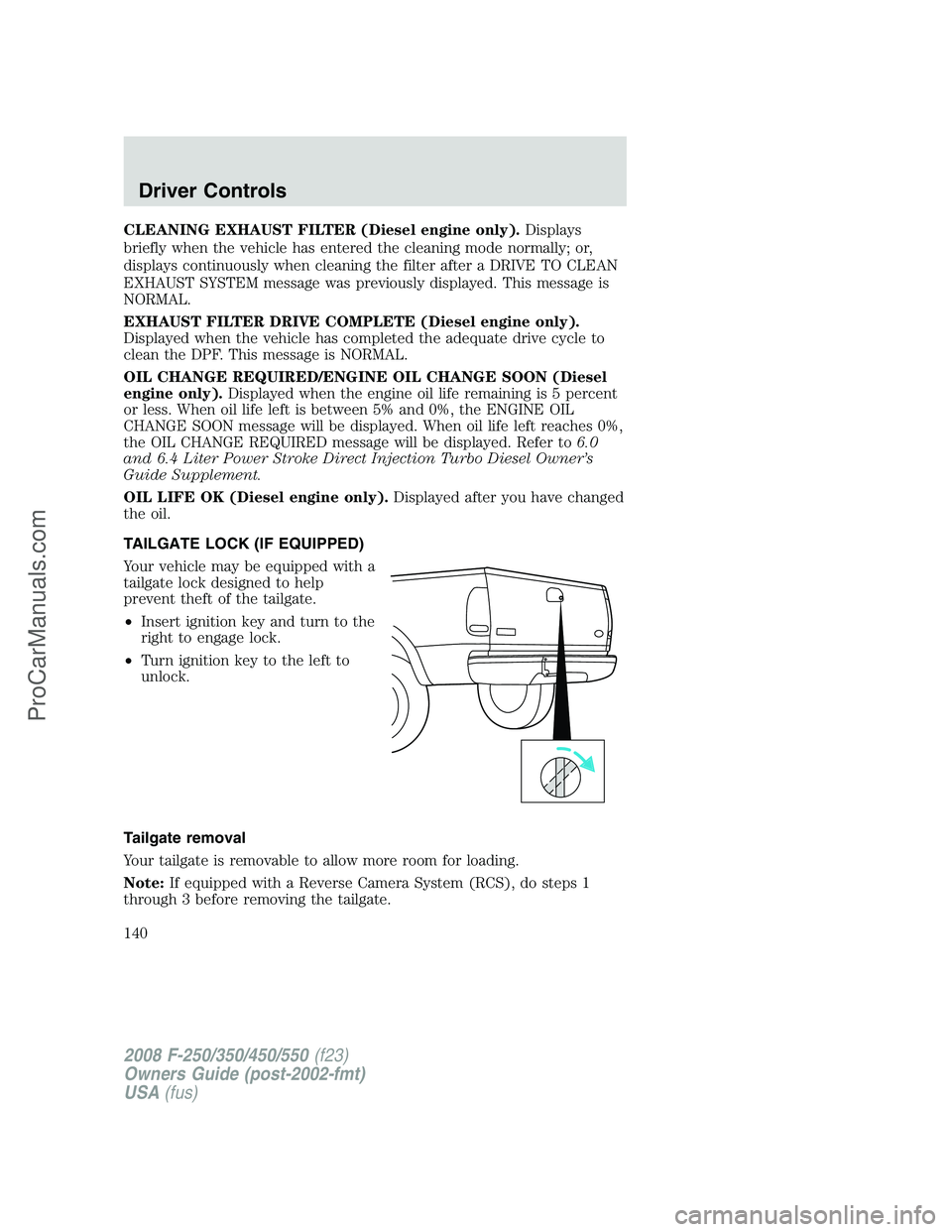
Your vehicle may be equipped with a
tailgate lock designed to help
prevent theft of the tailgate.
•Insert ignition key and turn to the
right to engage lock.
•Turn ignition key to the left to
unlock.
Tailgate removal
Your tailgate is removable to allow more room for loading.
Note:If equipped with a Reverse Camera System (RCS), do steps 1
through 3 before removing the tailgate.
2008 F-250/350/450/550(f23)
Owners Guide (post-2002-fmt)
USA(fus)
Driver Controls
140
ProCarManuals.com
Page 231 of 400
3. Press and hold the brake pedal for two (2) seconds, then release.
4. Turn the ignition to OFF/LOCK (DO NOTremove the key.)
5. Cycle the ignition from OFF/LOCK to RUN three (3) times ending in
RUN.DO NOTstart the engine.
If reset mode has been entered successfully, the horn will sound once,
the TPMS indicator will flash and the message center will displayTRAIN
LF TIRE.
If after repeated attempts to enter reset mode, the horn does not sound,
the TPMS indicator does not flash and the message center does not
display TRAIN LF TIRE, seek service from your authorized dealer.
TPMS reset sequence
The TPMS system needs to be reset starting with the left front tire in
the following clockwise order:
1. Left front tire
2. Right front tire
3. Right rear tire
4. Left rear tire
2008 F-250/350/450/550(f23)
Owners Guide (post-2002-fmt)
USA(fus)
Tires, Wheels and Loading
231
ProCarManuals.com
Page 247 of 400
The Ford TBC has only been verified to be compatible with
trailers having electric-actuated drum brakes (one to four axles)
and not hydraulic surge or electric-over-hydraulic types. It is the
responsibility of the customer to ensure that the trailer brakes are
adjusted appropriately, functioning normally and all electric
connections are properly made.
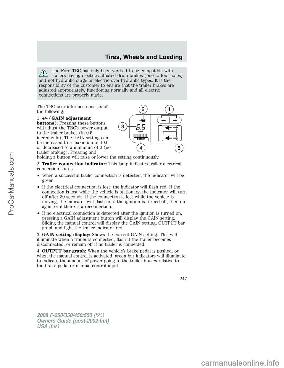
The TBC user interface consists of
the following:
1.+/- (GAIN adjustment
buttons):Pressing these buttons
will adjust the TBC’s power output
to the trailer brakes (in 0.5
increments). The GAIN setting can
be increased to a maximum of 10.0
or decreased to a minimum of 0 (no
trailer braking). Pressing and
holding a button will raise or lower the setting continuously.
2.Trailer connection indicator:This lamp indicates trailer electrical
connection status.
•When a successful trailer connection is detected, the indicator will be
green.
•If the electrical connection is lost, the indicator will flash red. If the
connection is lost while the vehicle is stationary, the indicator will turn
off after 30 seconds. If the connection is lost while the vehicle is
moving, the indicator will flash until the ignition is turned off, then on
again or if there is a reconnection.
•If no electrical connection is detected after the ignition is turned on,
pressing a GAIN adjustment button will display the GAIN setting.
Sliding the manual control will display the GAIN setting, OUTPUT bar
graph and light the trailer indicator red.
3.GAIN setting display:Shows the current GAIN setting. This will
illuminate when a trailer is connected, flash if the trailer becomes
disconnected, or remain off if no trailer is connected.
4.OUTPUT bar graph:When the vehicle’s brake pedal is pushed, or
when the manual control is activated, green bar indicators will illuminate
to indicate the amount of power going to the trailer brakes relative to
the brake pedal or manual control input.
2008 F-250/350/450/550(f23)
Owners Guide (post-2002-fmt)
USA(fus)
Tires, Wheels and Loading
247
ProCarManuals.com
Page 248 of 400
5.Manual control lever:Slide the control lever to the left to activate
power to the trailer’s electric brakes independent of the tow vehicle’s
brakes (see the followingProcedure for adjusting GAINsection for
instructions on proper use of this feature). If the manual control is
activated while the brake is also applied, the greater of the two inputs
determines the power sent to the trailer brakes.
•Stop Lamps:Activating the TBC manual control lever will illuminate
both the trailer brake lamps and the tow vehicle brake lamps except
the Center High-Mount Stop Lamp (presuming proper trailer electrical
connection). Pressing the vehicle brake pedal will also illuminate both
trailer and vehicle brake lamps.
GAIN:
The GAIN setting is used to set the TBC for the specific towing
condition and should be changed as towing conditions change. Changes
to towing conditions include trailer load, vehicle load, road conditions
and weather.
The GAIN should be set to provide the maximum trailer braking
assistance while ensuring the trailer wheels do not lock when braking.
Locked trailer wheels may lead to trailer instability.
Procedure for adjusting GAIN:
Note:This should only be performed in a traffic free environment at
speeds of approximately 20–25 mph (30–40 km/h).
1. Make sure the trailer brakes are in good working condition,
functioning normally, and properly adjusted. See your trailer dealer if
necessary.
2. Hook-up the trailer and make the electrical connections according to
the trailer manufacturer’s instructions.
3. When a trailer with electric brakes is plugged in, the trailer connection
indicator will illuminate green on the TBC and the GAIN setting display
will illuminate.
4. Use the GAIN adjustment (+/-) buttons to increase or decrease the
GAIN setting to the desired starting point. (A GAIN setting of 6.0 is a
good starting point for heavier loads.)
5. In a traffic-free environment, tow the trailer on a dry, level surface at
a speed of 20–25 mph (30–40 km/h) and squeeze the manual control
lever completely.
2008 F-250/350/450/550(f23)
Owners Guide (post-2002-fmt)
USA(fus)
Tires, Wheels and Loading
248
ProCarManuals.com
Page 249 of 400
6. If the trailer wheels lock-up (indicated by squealing tires), reduce the
GAIN setting; if the trailer wheels turn freely, increase the GAIN setting.
Repeat Steps 5 and 6 until the GAIN setting is at a point just below
trailer wheel lock-up. If towing a heavier trailer, trailer wheel lockup may
not be attainable even with the maximum GAIN setting of 10.
Explanation of instrument cluster messages:
The TBC interacts with the instrument cluster message center. These
messages, accompanied by a single chime, will be displayed when the
TBC determines a malfunction in the trailer connection, TBC system, or
in the trailer. These messages are listed below:
TRAILER DISCONNECTED (if equipped with message center) or
CHECK TRAILER (if equipped with mini message center):This
message is displayed when a trailer connection was determined and then
a disconnection, either intentionally or unintentionally, has been sensed
during a given ignition cycle. It is also displayed if a trailer fault occurs
causing the trailer to appear disconnected. This message is also
displayed during manual activation without a trailer connected.
TBC FAULT:This message is displayed in response to faults sensed by
the TBC. In the event this message is seen, please take your vehicle to
an authorized dealer for diagnosis and repair. The TBC may still function,
but performance may be degraded.
WIRING FAULT ON TRAILER:The TBC is capable of determining
certain faults in the vehicle wiring and trailer wiring/brake system. These
faults do not mean there is anything wrong with the TBC. This message
is displayed when one of the following faults has occurred:
•Short circuit on the electric brake output wire:If the TRAILER
FAULT message is displayed with no trailer connected, the problem is
with the vehicle wiring from the TBC to the 7–pin connector in the
bumper. If the message is only displayed with a trailer connected, the
problem is related to the trailer wiring; consult your trailer dealer for
assistance. This can be a short to ground (i.e., chaffed wire) or a short
to voltage (i.e., pulled pin on trailer emergency break-away battery) or
trailer brakes drawing too much current.
Note:Your TBC can be diagnosed by your authorized dealer to
determine exactly which trailer fault has occurred; however, if the fault
is with the trailer this diagnosis isnotcovered under your Ford
warranty.
Points to Remember:
•Remember to adjust gain setting before using the TBC for the first
time.
2008 F-250/350/450/550(f23)
Owners Guide (post-2002-fmt)
USA(fus)
Tires, Wheels and Loading
249
ProCarManuals.com
Page 250 of 400
•Readjust GAIN setting on the TBC (according to procedure above)
whenever road, weather and trailer or vehicle loading conditions
change from those that existed when the gain was initially set.
•The sliding lever on the TBC should be used only for manual
activation of trailer brakes to assist with proper adjustment of the
GAIN. Misuse, such as application during trailer sway, could cause
instability of trailer and/or tow vehicle.
•Avoid towing in adverse weather conditions. The TBC does not
provide anti-lock control of the trailer wheels. Trailer wheels can
lock-up on slippery surfaces, resulting in reduced stability of trailer
and tow vehicle.
•The TBC interacts with the brake system of the vehicle, including
ABS, in order to reduce the likelihood of trailer wheel lockup.
Therefore, if these systems are not functioning properly the TBC may
not function at full performance.
•When the vehicle is turned off, the TBC Output is disabled and the
display is shut down. Reactivation of the ignition from 3 (OFF) to 4
(ON) will awaken the TBC module.
•The TBC is only a factory or dealer installed item. Ford is not
responsible for warranty or performance of the TBC due to misuse or
customer installation.
•Do not attempt removal of the TBC without consulting the
Workshop Manual.Damage to the unit may result.
Trailer lamps
Trailer lamps are required on most towed vehicles. Make sure all running
lights, brake lights, turn signals and hazard lights are working. See your
authorized dealer or trailer rental agency for proper instructions and
equipment for hooking up trailer lamps.
Using a step bumper (if equipped)
The rear bumper is equipped with an integral hitch and only requires a
ball with a one inch (2.5 cm) shank diameter. The bumper has a 5,000
lb. (2,270 kg) trailer weight and 500 lb. (227 kg) tongue weight capacity.
If it is necessary to relocate the trailer hitch ball position, a
frame-mounted trailer hitch must be installed.
2008 F-250/350/450/550(f23)
Owners Guide (post-2002-fmt)
USA(fus)
Tires, Wheels and Loading
250
ProCarManuals.com
Page 274 of 400
If your vehicle sustains damage to the rear bumper/fascia, leaving
it misaligned or bent, the sensing zone may be altered causing
inaccurate measurement of obstacles or false alarms.
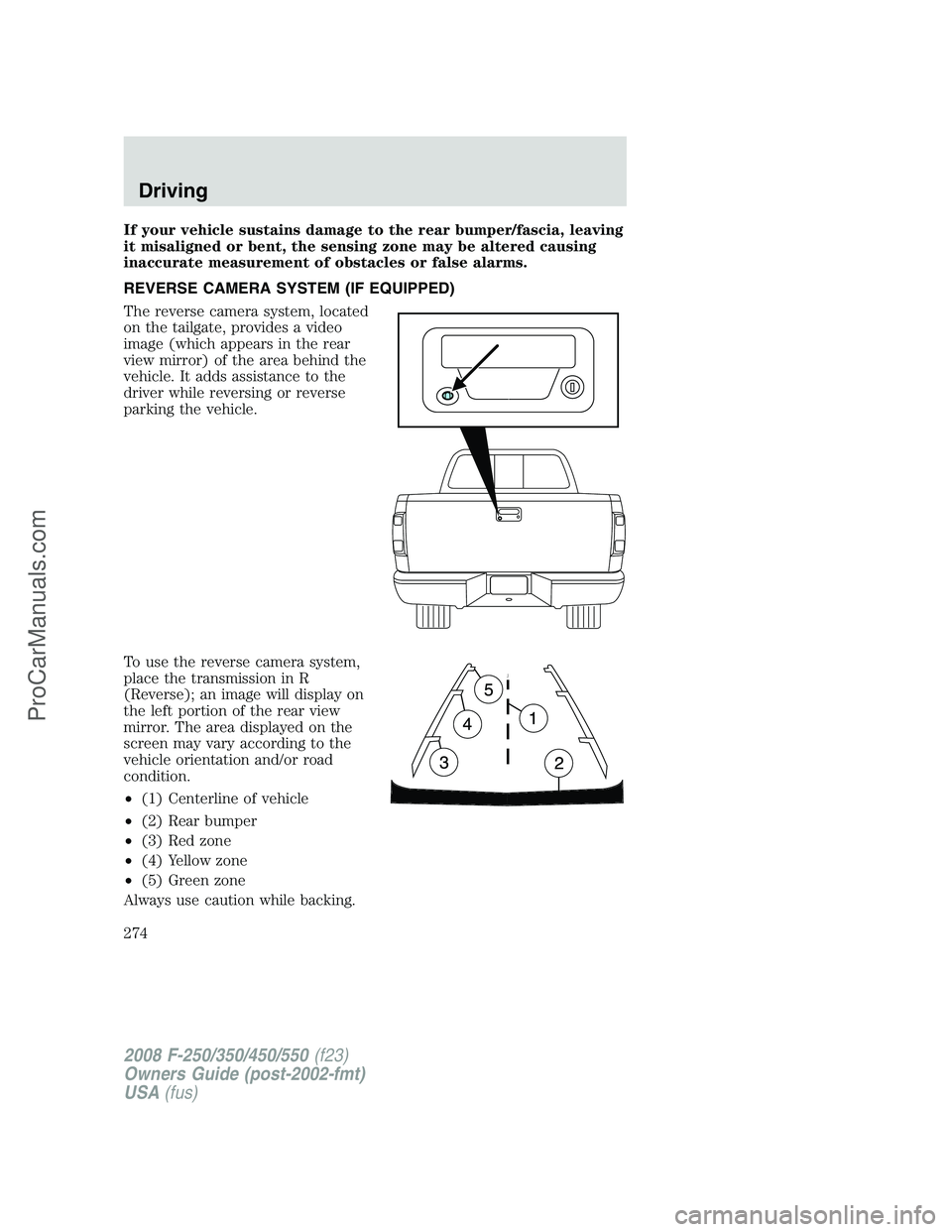
REVERSE CAMERA SYSTEM (IF EQUIPPED)
The reverse camera system, located
on the tailgate, provides a video
image (which appears in the rear
view mirror) of the area behind the
vehicle. It adds assistance to the
driver while reversing or reverse
parking the vehicle.
To use the reverse camera system,
place the transmission in R
(Reverse); an image will display on
the left portion of the rear view
mirror. The area displayed on the
screen may vary according to the
vehicle orientation and/or road
condition.
•(1) Centerline of vehicle
•(2) Rear bumper
•(3) Red zone
•(4) Yellow zone
•(5) Green zone
Always use caution while backing.
2008 F-250/350/450/550(f23)
Owners Guide (post-2002-fmt)
USA(fus)
Driving
274
ProCarManuals.com