display FORD F450 2011 Manual PDF
[x] Cancel search | Manufacturer: FORD, Model Year: 2011, Model line: F450, Model: FORD F450 2011Pages: 449, PDF Size: 5.83 MB
Page 279 of 449
Hill descent modes
• At speeds below 20 mph (32 km/h): When the HDC switch is pressed
and HDC is active, the HDC telltale will flash.
• At speeds below 20 mph (32 km/h): When the HDC switch is pressed
and conditions are not correct for hill descent activation, the HDC
system will be enabled, the light in the cluster will be on solid and
HILL DESCENT CONTROL READY will be displayed in the message
center.
• At speeds above 20 mph (32 km/h): When the HDC switch is pressed,
the HDC system will be enabled, the light in the cluster will not be
illuminated and FOR HILL CNTRL, 20 MPH OR LESS will be displayed
in the message center.
Refer to Message center in the Instrument Cluster chapter for hill
descent control messages.
STEERING
To help prevent damage to the power steering system:
• Never hold the steering wheel at its furthest turning points (until it
stops) for more than three to five seconds when the engine is running.
• Do not operate the vehicle with a low power steering pump fluid level
(below the MIN mark on the reservoir).
• Some noise is normal during operation. If excessive, check for low
power steering pump fluid level before seeking service by your dealer.
• Heavy or uneven efforts may be caused by low power steering fluid.
Check for low power steering pump fluid level before seeking service
by your dealer.
• Do not fill the power steering pump reservoir above the MAX mark on
the reservoir, as this may result in leaks from the reservoir.
If the power steering system breaks down (or if the engine is turned
off), you can steer the vehicle manually, but it takes more effort.
If the steering wanders or pulls, check for:
• an improperly inflated tire
• uneven tire wear
• loose or worn suspension components
• loose or worn steering components
• improper steering alignment Driving
279
2011 F-250/350/450/550 (f23)
Owners Guide, 4th Printing
USA (fus)
Page 280 of 449
If any steering components are serviced or replaced, install new
fasteners (many are coated with thread adhesive or have prevailing
torque features which may not be re-used). Never re-use a bolt or nut.
Torque fasteners to specifications in Workshop Manual .
A high crown in the road or high crosswinds may also make the steering
seem to wander/pull.
ELECTRONIC LOCKING DIFFERENTIAL (ELD) (IF EQUIPPED)
The electronic locking differential (ELD) is a device housed in the rear
axle which allows both rear wheels to turn at the same speed. It provides
added traction on slippery and/or off road surfaces, particularly when
one wheel is on a poor traction surface. The ELD may be locked or
unlocked by the vehicle operator and can be engaged or disengaged on
the fly. When the axle is unlocked it will function like a standard rear
axle. When the axle is locked it will not allow the rear wheels to rotate
at different speeds when turning. It is not recommended for use on good
traction surfaces such as dry pavement. Doing so may result in abnormal
driving behavior and noise while cornering and excessive tire wear.
The ELD is affected by the following conditions of your vehicle:
• On 2WD vehicles and 4WD vehicles in 2H (4X2) or 4H (4X4 High),
the ELD will not engage if the vehicle speed is above 25 mph
(40 km/h).
• On 2WD vehicles and 4WD vehicles in 2H (4X2) or 4H (4X4 High),
the ELD will automatically disengage at speeds above 25 mph
(40 km/h) and will automatically reengage at speeds below 19 mph
(30 km/h).
• On 4WD vehicles in 4L (4X4 Low), the ELD can be engaged at any
speed and will not automatically disengage.
Activating the electronic locking differential (ELD)
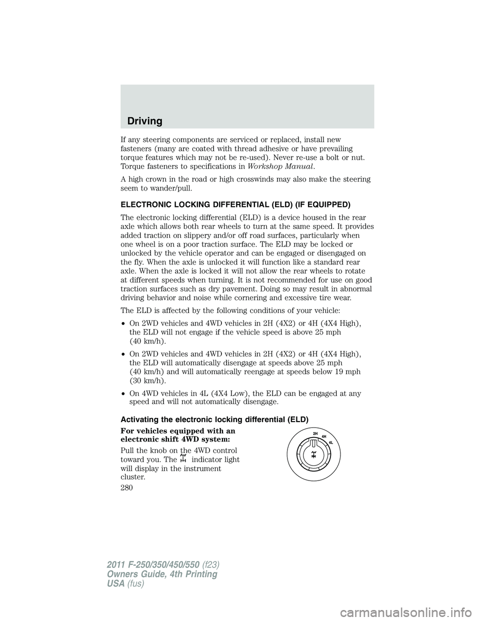
For vehicles equipped with an
electronic shift 4WD system:
Pull the knob on the 4WD control
toward you. The
indicator light
will display in the instrument
cluster.Driving
280
2011 F-250/350/450/550 (f23)
Owners Guide, 4th Printing
USA (fus)
Page 281 of 449
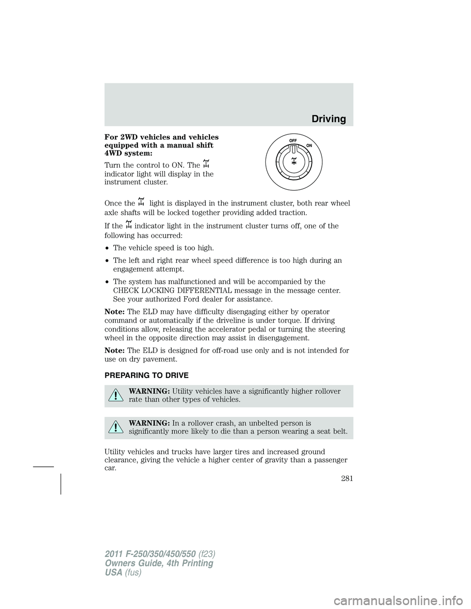
For 2WD vehicles and vehicles
equipped with a manual shift
4WD system:
Turn the control to ON. The
indicator light will display in the
instrument cluster.
Once the light is displayed in the instrument cluster, both rear wheel
axle shafts will be locked together providing added traction.
If the
indicator light in the instrument cluster turns off, one of the
following has occurred:
• The vehicle speed is too high.
• The left and right rear wheel speed difference is too high during an
engagement attempt.
• The system has malfunctioned and will be accompanied by the
CHECK LOCKING DIFFERENTIAL message in the message center.
See your authorized Ford dealer for assistance.
Note: The ELD may have difficulty disengaging either by operator
command or automatically if the driveline is under torque. If driving
conditions allow, releasing the accelerator pedal or turning the steering
wheel in the opposite direction may assist in disengagement.
Note: The ELD is designed for off-road use only and is not intended for
use on dry pavement.
PREPARING TO DRIVE
WARNING: Utility vehicles have a significantly higher rollover
rate than other types of vehicles.
WARNING: In a rollover crash, an unbelted person is
significantly more likely to die than a person wearing a seat belt.
Utility vehicles and trucks have larger tires and increased ground
clearance, giving the vehicle a higher center of gravity than a passenger
car. Driving
281
2011 F-250/350/450/550 (f23)
Owners Guide, 4th Printing
USA (fus)
Page 290 of 449
All available gears will be displayed with the current gear indicated.
Press the – button again to lock out gears beginning with the highest
gear. Example: press the – button twice to lock out 6th and 5th gears.
Only the available gears will be displayed and the transmission will
automatically shift between the available gears. Press the + button to
unlock gears.
By moving the gearshift lever from the D (Drive) position to the M
(Manual) position you may now manually select the gear you desire.
Only the current gear will be displayed. Press the + button or the –
button to upshift or downshift. If the – button is pressed at a vehicle
speed that would cause an engine overspeed, the requested gear will
flash then disappear and the transmission will remain in the current gear.
Recommended shift speeds
Upshift according to the following chart:
Upshifts when accelerating (recommended for best fuel
economy)
Shift from: Gasoline engines Diesel engines
1 – 2 15 mph (24 km/h) 12 mph (19 km/h)
2 – 3 25 mph (40 km/h) 19 mph (31 km/h)
3 – 4 40 mph (64 km/h) 26 mph (42 km/h)
4 – 5 45 mph (72 km/h) 34 mph (55 km/h)
5 – 6 50 mph (80 km/h) 46 mph (74 km/h)
In order to prevent the engine from running at too low an RPM, which
may cause it to stall, the SST will still automatically make some
downshifts if it has determined that you have not downshifted in time.
Although the SST will make some downshifts for you, it will still allow
you to downshift at any time as long as the SST determines that the
engine will not be damaged from over-revving.
The SST will not automatically upshift, even if the engine is approaching
the RPM limit. It must be shifted manually by pressing the + button.
Engine damage may occur if excessive engine revving is held
without shifting.Driving
290
2011 F-250/350/450/550 (f23)
Owners Guide, 4th Printing
USA (fus)
Page 293 of 449
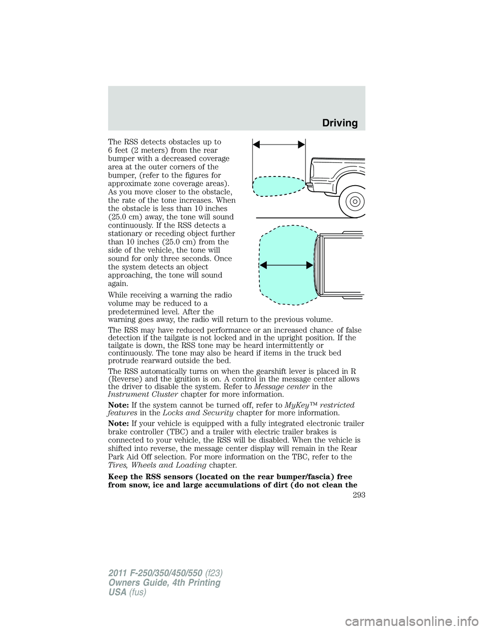
The RSS detects obstacles up to
6 feet (2 meters) from the rear
bumper with a decreased coverage
area at the outer corners of the
bumper, (refer to the figures for
approximate zone coverage areas).
As you move closer to the obstacle,
the rate of the tone increases. When
the obstacle is less than 10 inches
(25.0 cm) away, the tone will sound
continuously. If the RSS detects a
stationary or receding object further
than 10 inches (25.0 cm) from the
side of the vehicle, the tone will
sound for only three seconds. Once
the system detects an object
approaching, the tone will sound
again.
While receiving a warning the radio
volume may be reduced to a
predetermined level. After the
warning goes away, the radio will return to the previous volume.
The RSS may have reduced performance or an increased chance of false
detection if the tailgate is not locked and in the upright position. If the
tailgate is down, the RSS tone may be heard intermittently or
continuously. The tone may also be heard if items in the truck bed
protrude rearward outside the bed.
The RSS automatically turns on when the gearshift lever is placed in R
(Reverse) and the ignition is on. A control in the message center allows
the driver to disable the system. Refer to Message center in the
Instrument Cluster chapter for more information.
Note: If the system cannot be turned off, refer to MyKey™ restricted
features in the Locks and Security chapter for more information.
Note: If your vehicle is equipped with a fully integrated electronic trailer
brake controller (TBC) and a trailer with electric trailer brakes is
connected to your vehicle, the RSS will be disabled. When the vehicle is
shifted into reverse, the message center display will remain in the Rear
Park Aid Off selection. For more information on the TBC, refer to the
Tires, Wheels and Loading chapter.
Keep the RSS sensors (located on the rear bumper/fascia) free
from snow, ice and large accumulations of dirt (do not clean the Driving
293
2011 F-250/350/450/550 (f23)
Owners Guide, 4th Printing
USA (fus)
Page 294 of 449
sensors with sharp objects). If the sensors are covered, it will
affect the accuracy of the RSS.
If your vehicle sustains damage to the rear bumper/fascia, leaving
it misaligned or bent, the sensing zone may be altered causing
inaccurate measurement of obstacles or false alarms.
REARVIEW CAMERA SYSTEM (IF EQUIPPED)
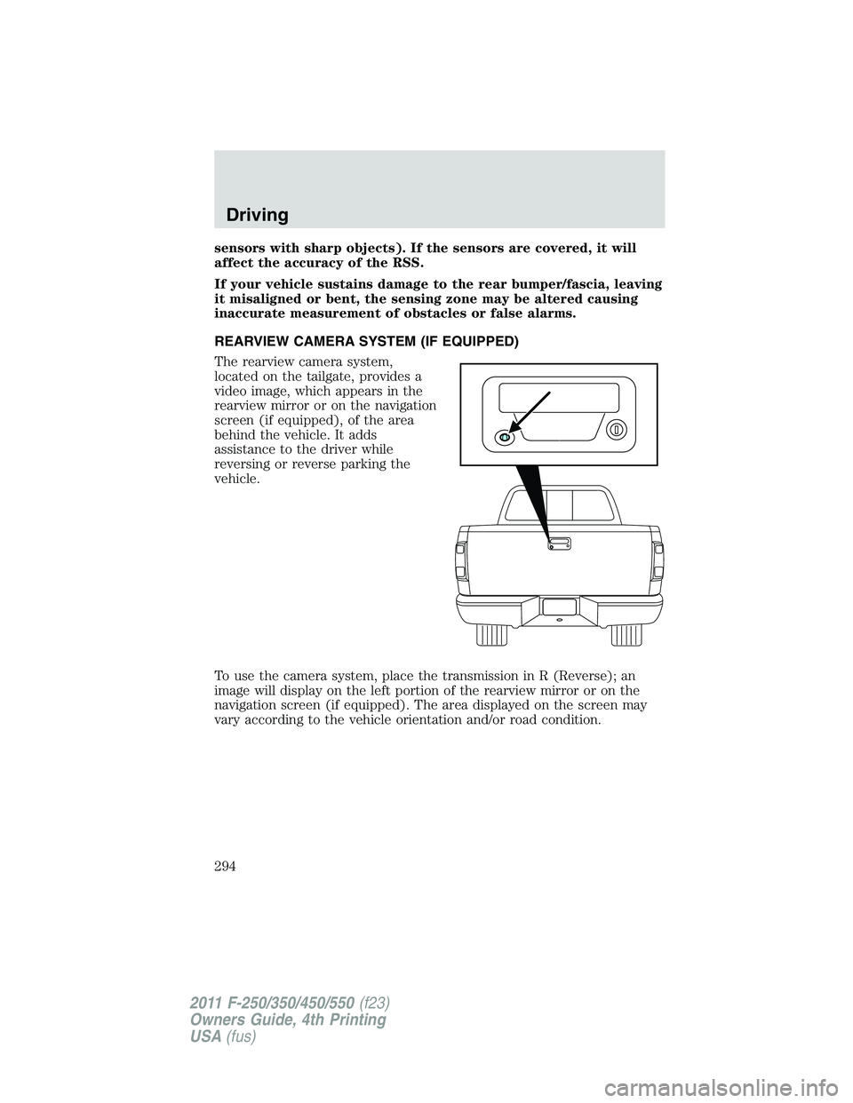
The rearview camera system,
located on the tailgate, provides a
video image, which appears in the
rearview mirror or on the navigation
screen (if equipped), of the area
behind the vehicle. It adds
assistance to the driver while
reversing or reverse parking the
vehicle.
To use the camera system, place the transmission in R (Reverse); an
image will display on the left portion of the rearview mirror or on the
navigation screen (if equipped). The area displayed on the screen may
vary according to the vehicle orientation and/or road condition.Driving
294
2011 F-250/350/450/550 (f23)
Owners Guide, 4th Printing
USA (fus)
Page 295 of 449
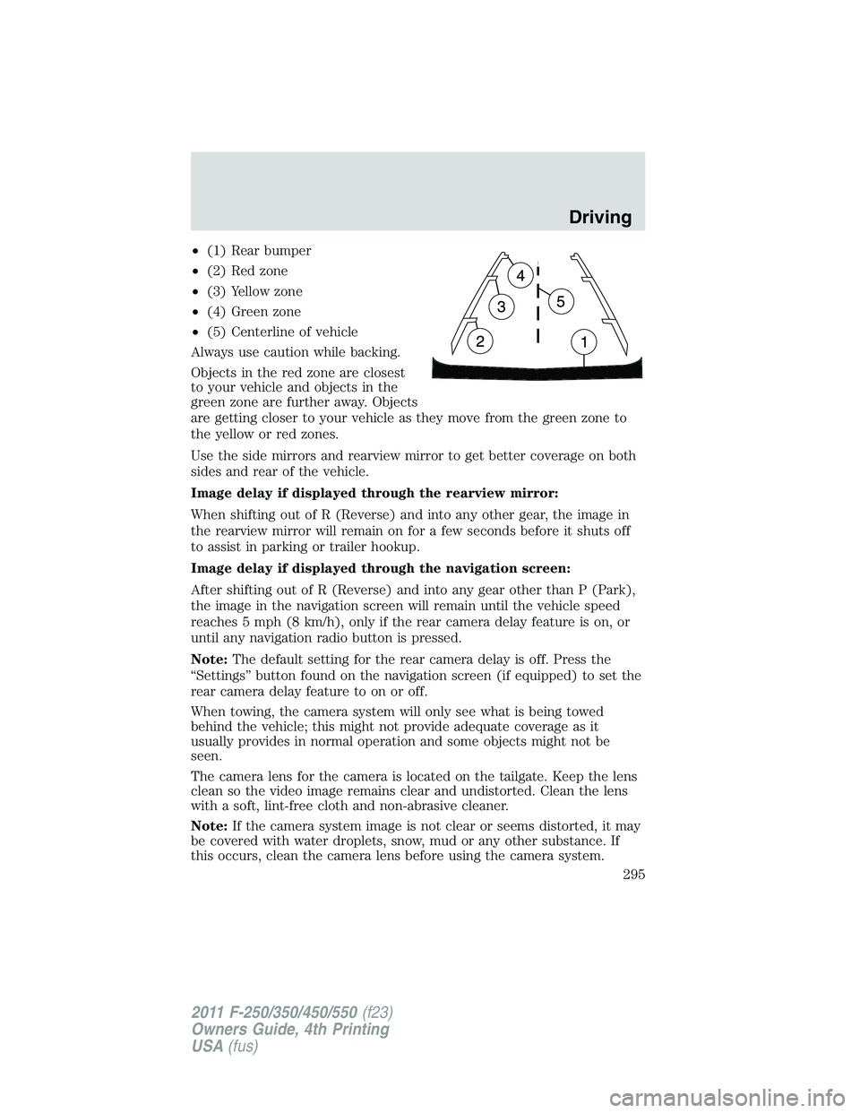
• (1) Rear bumper
• (2) Red zone
• (3) Yellow zone
• (4) Green zone
• (5) Centerline of vehicle
Always use caution while backing.
Objects in the red zone are closest
to your vehicle and objects in the
green zone are further away. Objects
are getting closer to your vehicle as they move from the green zone to
the yellow or red zones.
Use the side mirrors and rearview mirror to get better coverage on both
sides and rear of the vehicle.
Image delay if displayed through the rearview mirror:
When shifting out of R (Reverse) and into any other gear, the image in
the rearview mirror will remain on for a few seconds before it shuts off
to assist in parking or trailer hookup.
Image delay if displayed through the navigation screen:
After shifting out of R (Reverse) and into any gear other than P (Park),
the image in the navigation screen will remain until the vehicle speed
reaches 5 mph (8 km/h), only if the rear camera delay feature is on, or
until any navigation radio button is pressed.
Note: The default setting for the rear camera delay is off. Press the
“Settings” button found on the navigation screen (if equipped) to set the
rear camera delay feature to on or off.
When towing, the camera system will only see what is being towed
behind the vehicle; this might not provide adequate coverage as it
usually provides in normal operation and some objects might not be
seen.
The camera lens for the camera is located on the tailgate. Keep the lens
clean so the video image remains clear and undistorted. Clean the lens
with a soft, lint-free cloth and non-abrasive cleaner.
Note: If the camera system image is not clear or seems distorted, it may
be covered with water droplets, snow, mud or any other substance. If
this occurs, clean the camera lens before using the camera system. Driving
295
2011 F-250/350/450/550 (f23)
Owners Guide, 4th Printing
USA (fus)
Page 298 of 449
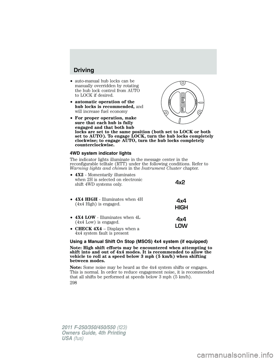
• auto-manual hub locks can be
manually overridden by rotating
the hub lock control from AUTO
to LOCK if desired.
• automatic operation of the
hub locks is recommended, and
will increase fuel economy
• For proper operation, make
sure that each hub is fully
engaged and that both hub
locks are set to the same position (both set to LOCK or both
set to AUTO). To engage LOCK, turn the hub locks completely
clockwise; to engage AUTO, turn the hub locks completely
counterclockwise.
4WD system indicator lights
The indicator lights illuminate in the message center in the
reconfigurable telltale (RTT) under the following conditions. Refer to
Warning lights and chimes in the Instrument Cluster chapter.
• 4X2 - Momentarily illuminates
when 2H is selected on electronic
shift 4WD systems only.
• 4X4 HIGH - Illuminates when 4H
(4x4 High) is engaged.
• 4X4 LOW - Illuminates when 4L
(4x4 Low) is engaged.
• CHECK 4X4 – Displays when a
4x4 system fault is present
Using a Manual Shift On Stop (MSOS) 4x4 system (if equipped)
Note: High shift efforts may be encountered when attempting to
shift into and out of 4x4 modes. It is recommended to allow the
vehicle to roll at a speed below 3 mph (5 km/h) when shifting
between modes.
Note: Some noise may be heard as the 4x4 system shifts or engages.
This is normal. In order to reduce engagement noise, it is recommended
that all shifts be performed at speeds below 3 mph (5 km/h). 4x2
4x4
HIGH
4x4
LOWDriving
298
2011 F-250/350/450/550 (f23)
Owners Guide, 4th Printing
USA (fus)
Page 302 of 449
4L (4X4 Low) - Uses extra gearing to provide maximum power to all
four wheels at reduced speeds. Intended only for off-road applications
such as deep sand, steep grades or pulling heavy objects. 4L (4X4 low)
will not engage while the vehicle is moving above 3 mph (5 km/h); this is
normal and should be no reason for concern. Refer to Shifting to/from
4L (4X4 low) for proper operation.
Shifting between 2H (4X2) and 4H (4X4 high)
Move the 4WD control between 2H (4X2) and 4H (4X4 high) at any
forward speed. The message center will display 4X4 SHIFT IN
PROGRESS during the system shift. “4X4 HIGH” will display in the
message center if 4H is selected and “4X2” will momentarily display in
the message center if 2H is selected.
If SHIFT DELAYED PULL FORWARD is displayed in the message
center during the mode shift, transfer case gear tooth blockage is
present. To alleviate this condition, place the transmission in a forward
gear and move the vehicle forward approximately 5 feet (2 meters) to
allow the transfer case to complete the mode shift.
Note: Momentarily releasing the accelerator pedal while performing a
shift will improve engagement/disengagement times.
Note: Do not perform this operation if the rear wheels are slipping.
Note: Some noise may be heard as the system shifts or engages; this is
normal.
Note: 4X4 high mode is not intended for use on dry pavement.
Shifting to/from 4L (4X4 low)
1. Bring the vehicle to a speed of 3 mph (5 km/h) or less.
2. Place the transmission in N (Neutral).
3. Move the 4WD control to the desired position.
The message center will display 4X4 SHIFT IN PROGRESS during the
shift. The message center will then display the system mode selected. If
any of the above shift conditions are not met, the shift will not occur and
the message center will display information guiding the driver through
the proper shifting procedures.
If SHIFT DELAYED PULL FORWARD is displayed in the message
center, transfer case gear tooth blockage is present. To alleviate this
condition, place the transmission in a forward gear, move the vehicle
forward approximately 5 feet (1.5 m), and shift the transmission back to
neutral to allow the transfer case to complete the range shift.Driving
302
2011 F-250/350/450/550 (f23)
Owners Guide, 4th Printing
USA (fus)