headlamp FORD F650 2000 10.G Owners Manual
[x] Cancel search | Manufacturer: FORD, Model Year: 2000, Model line: F650, Model: FORD F650 2000 10.GPages: 208, PDF Size: 1.08 MB
Page 8 of 208
0
000000000
MPH20km/h
406080
100
120
140
160
010 20304050
60
70
80
90
100
P
ABS TRAILER
BRAKE
W
A
TE
R
IN
F
U
E
L W
A
I
T
O
S
T
A
ABS
TRANS
TEMP STOP
ENGINE
ENGINE
PROTECT
AIR
CLEAN
CHECK
TRANS SERVICE
ENGINE
SOONCRUIS
+ -LEF
HRPM1
0
0
0 D
IE
S
E
L
F
U
E
L
O
N
L
YX012
3
4
PRN 218C 1
8
H
D
!B
R
A
K
E
B
R
A
K
E
0 30120 90 60
150AIR
PRESSURE
PSIP
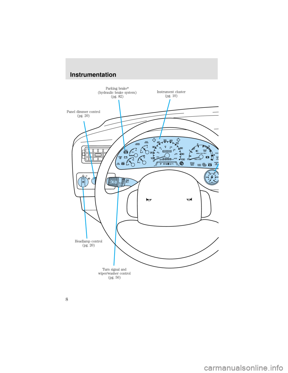
Headlamp control
(pg. 20)Instrument cluster
(pg. 10)
Panel dimmer control
(pg. 20)
Turn signal and
wiper/washer control
(pg. 50) Parking brake*
(hydraulic brake system)
(pg. 82)
Instrumentation
8
Page 12 of 208
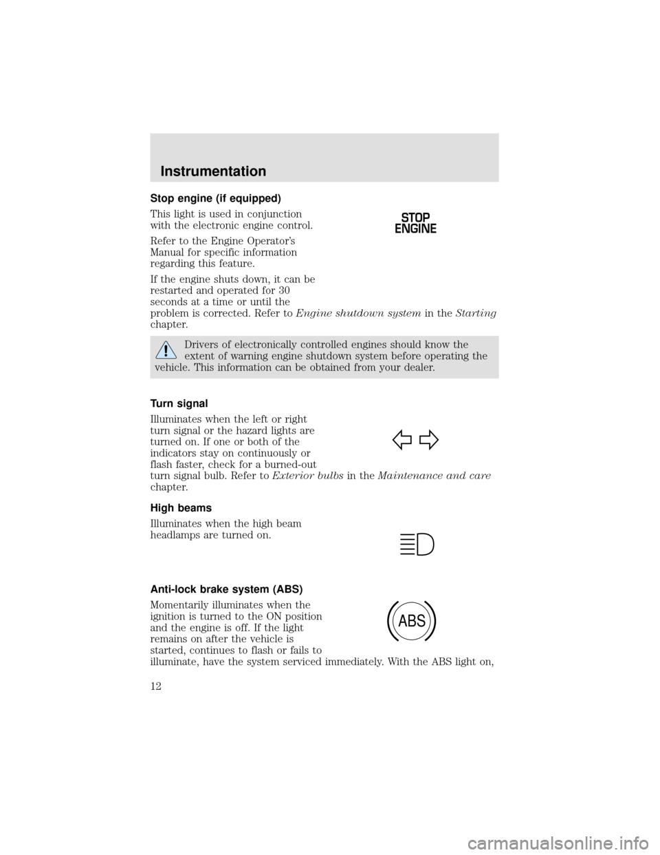
Stop engine (if equipped)
This light is used in conjunction
with the electronic engine control.
Refer to the Engine Operator’s
Manual for specific information
regarding this feature.
If the engine shuts down, it can be
restarted and operated for 30
seconds at a time or until the
problem is corrected. Refer toEngine shutdown systemin theStarting
chapter.
Drivers of electronically controlled engines should know the
extent of warning engine shutdown system before operating the
vehicle. This information can be obtained from your dealer.
Turn signal
Illuminates when the left or right
turn signal or the hazard lights are
turned on. If one or both of the
indicators stay on continuously or
flash faster, check for a burned-out
turn signal bulb. Refer toExterior bulbsin theMaintenance and care
chapter.
High beams
Illuminates when the high beam
headlamps are turned on.
Anti-lock brake system (ABS)
Momentarily illuminates when the
ignition is turned to the ON position
and the engine is off. If the light
remains on after the vehicle is
started, continues to flash or fails to
illuminate, have the system serviced immediately. With the ABS light on,
STOP
ENGINE
ABS
Instrumentation
12
Page 15 of 208
These and other temporary malfunctions can be corrected by filling the
fuel tank with good quality fuel. After three driving cycles without these
or any other temporary malfunctions present, theService Engine Soon
light should turn off. (A driving cycle consists of a cold engine startup
followed by mixed city/highway driving.) No additional vehicle service is
required.
If theService Engine Soonlight remains on, have your vehicle serviced
at the first available opportunity.
Under engine misfire conditions, excessive exhaust temperatures
could damage the fuel system, interior floor coverings or other
vehicle components, possibly causing a fire.
Key-in-ignition warning chime
Sounds when the ignition key is left in the ignition in the OFF/LOCK or
ACC position and the driver’s door is opened.
Headlamps on warning chime
Sounds when the headlamps or parking lamps are on, the ignition is off
(and the key is not in the ignition) and the driver’s door is opened.
Safety belt warning chime
Sounds to remind you to fasten your safety belts.
For information on the safety belt warning chime, refer to theSeating
and safety restraintschapter.
Instrumentation
15
Page 20 of 208
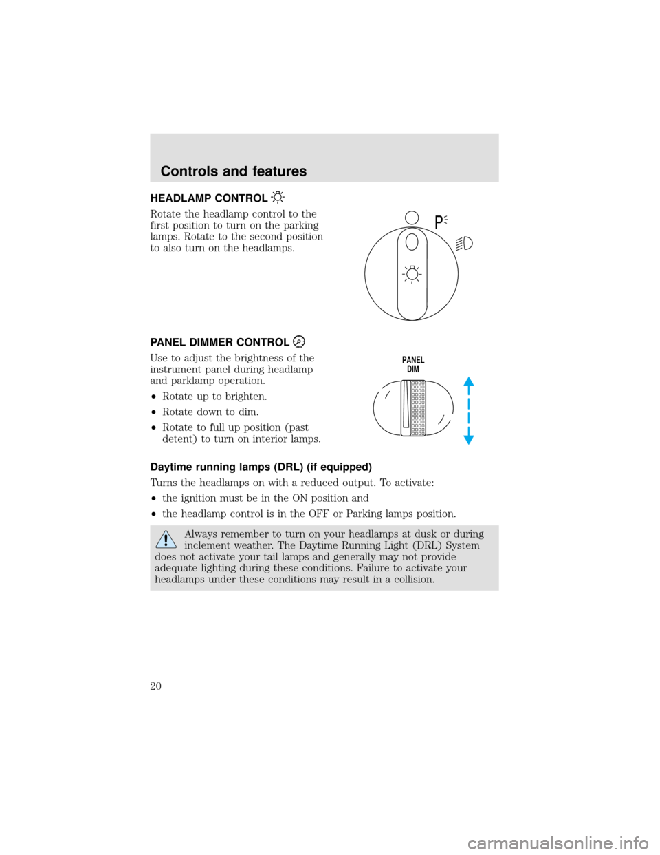
HEADLAMP CONTROL
Rotate the headlamp control to the
first position to turn on the parking
lamps. Rotate to the second position
to also turn on the headlamps.
PANEL DIMMER CONTROL
Use to adjust the brightness of the
instrument panel during headlamp
and parklamp operation.
•Rotate up to brighten.
•Rotate down to dim.
•Rotate to full up position (past
detent) to turn on interior lamps.
Daytime running lamps (DRL) (if equipped)
Turns the headlamps on with a reduced output. To activate:
•the ignition must be in the ON position and
•the headlamp control is in the OFF or Parking lamps position.
Always remember to turn on your headlamps at dusk or during
inclement weather. The Daytime Running Light (DRL) System
does not activate your tail lamps and generally may not provide
adequate lighting during these conditions. Failure to activate your
headlamps under these conditions may result in a collision.
P
PANEL
DIM
Controls and features
20
Page 69 of 208
One time disable
Anytime the safety belt is buckled and then unbuckled during an ignition
ON cycle, Belt Minder will be disabled for that ignition cycle only.
Deactivating/activating the belt minder feature
Read steps1-9thoroughly before proceeding with the
deactivation/activation programming procedure.
The Belt Minder feature can be deactivated/activated by performing the
following procedure:
Before following the procedure, make sure that:
•the parking brake is set
•the gearshift is in P (Park) (automatic transmission) or the neutral
position (manual transmission).
•the ignition switch is in the OFF position
•all vehicle doors are closed
•the driver’s safety belt is unbuckled
•the parklamps/headlamps are in OFF position (If vehicle is equipped
with Autolamps, this will not affect the procedure.)
To reduce the risk of injury, do not deactivate/activate the Belt
Minder feature while driving the vehicle.
1. Turn the ignition switch to the RUN (or ON) position. (DO NOT
START THE ENGINE)
2. Wait until the safety belt warning light turns off. (Approximately 1–2
minutes)
•Steps 3–5 must be completed within 60 seconds or the procedure will
have to be repeated.
3. Buckle then unbuckle the safety belt three times, ending with the
safety belt unbuckled. This can be done before or during Belt Minder
warning activation.
4. Turn on the parklamps/headlamps, turn off the parklamps/headlamps.
5. Buckle then unbuckle the safety belt three times, ending with the
safety belt unbuckled.
•After step 5 the safety belt warning light will be turned on for three
seconds.
Seating and safety restraints
69
Page 77 of 208
STARTING PROCEDURES
Operating precautions
•Always shift to a lower gear at high altitudes to prevent engine
smoking.
•Avoid extended and unnecessary idling.
Do not operate a diesel engine where the vapors can be
combustible. These vapors can be sucked through the air intake
system and cause engine acceleration and overspeeding, which may
result in bodily injury and extensive property damage. The equipment
owner and operator are responsible for safe operation in a hostile
environment.
STARTING THE ENGINE
1. Ensure headlamps and all accessories are turned off and the parking
brake is applied.
2.Automatic transmissions,ensure gearshift is in N (Neutral).
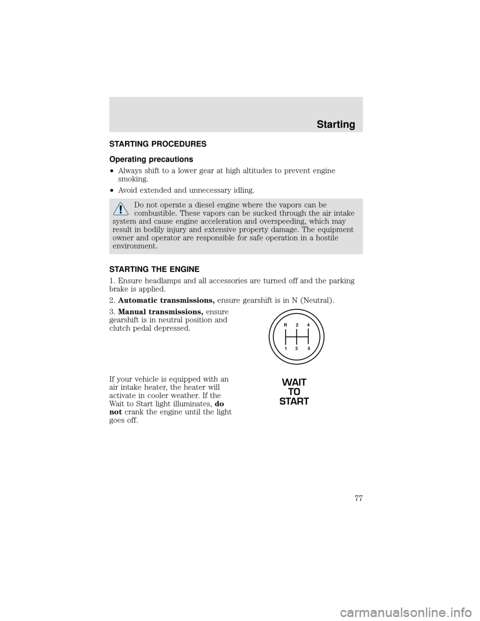
3.Manual transmissions,ensure
gearshift is in neutral position and
clutch pedal depressed.
If your vehicle is equipped with an
air intake heater, the heater will
activate in cooler weather. If the
Wait to Start light illuminates,do
notcrank the engine until the light
goes off.
R 2 4
3 5 1
WAIT
TO
START
Starting
77
Page 117 of 208

The fuses are coded as follows.
Fuse/Relay
LocationFuse Amp
RatingPassenger Compartment
Fuse Panel Description
1 20A Horn
2 15A Turn/Hazard Lamps
3 20A Cigar Lighter
4 10A Diagnostic Connectors
5 15A Back-Up Lamps, DRL Relays, Blend Door
Actuator
6—Not Used
7—Not Used
8 5A Radio, GEM
9 5A Switch Illumination (Headlamp, Power
Windows, Power Door Locks), Power
Window Relay
10—Not Used
11 30A Wiper Motor, Washer Pump Relay
12 10A Stoplamp Switch (Hydraulic Vehicles Only)
Relay #1
Relay #2
Relay #3
Horn
Relay #4
Relay #5 One Touch
Down Interior
Lamps#1
#12#22
#2
#3
#4
#5
#6
#7
#8
#9
#10
#11#13
#23
#14
#15
#16
#17#24
#25
#26
#27
#18
#28
#19
#29
#20
#21#30
#31
Roadside emergencies
117
Page 118 of 208

Fuse/Relay
LocationFuse Amp
RatingPassenger Compartment
Fuse Panel Description
13 20A Radio, Cluster, 7.3L Power Stroke
Powertrain Control Module (PCM), Keep
Alive Memory
14 10A Interior Lamps
15 10A GEM, Interior Lamp Relay
16 15A Highbeams
17—Not Used
18 5A Headlamp switch, GEM
19 15A Engine, Cluster, Cummins PC M, CAT PCM,
7.3L Power Stroke PCM (Idle Valid Switch
Input)
20 15A Starter Relay, GEM
21 10A Daytime Running Lamps (DRL)
22 15A Not Used (Spare)
23 10A Electronic Flasher
24 15A Vacuum Pump, Air Dryer, ABS, Fuel Heater
Relay
25 10A Blower Motor Relay
26 10A Right Low Beam Headlamp
27—Not Used
28 10A Left Low Beam Headlamp
29 10A Cluster, GEM, 7.3L Power Stroke PCM
(clutch switch input), APCM (7.3L Power
Stroke only)
30 30A 7.3L Power Stroke PCM Diode, 7.3L Power
Stroke Fuel Heater
31 15A Allison MD Transmission, Neutral Start
Relay and PCM (7.3L Power Stroke only)
Relay 1—Interior Lamps
Relay 2—Not Used
Relay 3—Horn
Relay 4—One Touch Down
Relay 5—Not Used
Roadside emergencies
118
Page 120 of 208

Fuse/Relay
LocationFuse Amp
RatingPower Distribution Box Description
7 15A* Stop Lamps
8 25A* C AT Fuel Heater
9—Not Used
10 15A* Shift Modulator (Allison AT trans only)
11 20A* Allison MD Trans
12—Not Used
13—Not Used
14—Not Used
15 7.5A*
Body Builder Prep (Hydraulic Vehicles Only)
16—Not Used
17—Not Used
18—Not Used
19—Not Used
20—Not Used
21 10A* GEM (Hydraulic Vehicles Only)
22—Not Used
23—Not Used
24—Not Used
101 40A** ABS (Air Only)
102 20A** Body Builder Prep Run Feed
103 50A** Ignition Switch (JB fuses 8, 9, 11, 19, 20,
22, 23, 24, 25, 29, 30, 31)
104 20A** Power Point
105 20A** Power Door Locks
106 30A** Headlamps
107 50A** Junction Box Battery Feed (fuses 1, 2, 3, 4,
12, 13, 14, 15)
108 40A** Cummins Fuel Heater
109 40A** Power Windows
110—Not Used
111 30A** Body Builder Prep
Roadside emergencies
120
Page 159 of 208

Driving style—good driving and fuel economy habits
Give consideration to the lists that follow and you may be able to change
a number of variables and improve your fuel economy.
Habits
•Smooth, moderate operation can yield up to 10% savings in fuel.
•Steady speeds without stopping will usually give the best fuel
economy.
•Anticipate stopping; slowing down may eliminate the need to stop.
•Sudden or hard accelerations may reduce fuel economy.
•Slow down gradually.
•Driving at reasonable speeds (traveling at 88 km/h [55 mph] uses 15%
less fuel than traveling at 105 km/h [65 mph]).
•Using the air conditioner or defroster may reduce fuel economy.
•Resting your foot on the brake pedal while driving may reduce fuel
economy.
Conditions
•Carrying unnecessary weight may reduce fuel economy.
•Fuel economy may decrease with lower temperatures during the first
12–16 km (8–10 miles) of driving.
•Flat terrain driving improves fuel economy over hilly roads.
•Transmissions give their best fuel economy when operated in the top
cruise gear and with steady pressure on the accelerator.
•Close windows for highway driving.
EXTERIOR BULBS
Check operation of lamps, safety equipment and warning signals
It is a good safety practice to check operation of headlamps, parking
lamps, turn signals, clearance and marker lamps, instrument panel and
control lamps each day.
Replacing headlamp bulbs
To remove the headlamp bulbs:
1. Make sure headlamp switch is in OFF position.
Maintenance and care
159