service indicator FORD F650 2000 10.G Owners Manual
[x] Cancel search | Manufacturer: FORD, Model Year: 2000, Model line: F650, Model: FORD F650 2000 10.GPages: 208, PDF Size: 1.08 MB
Page 12 of 208
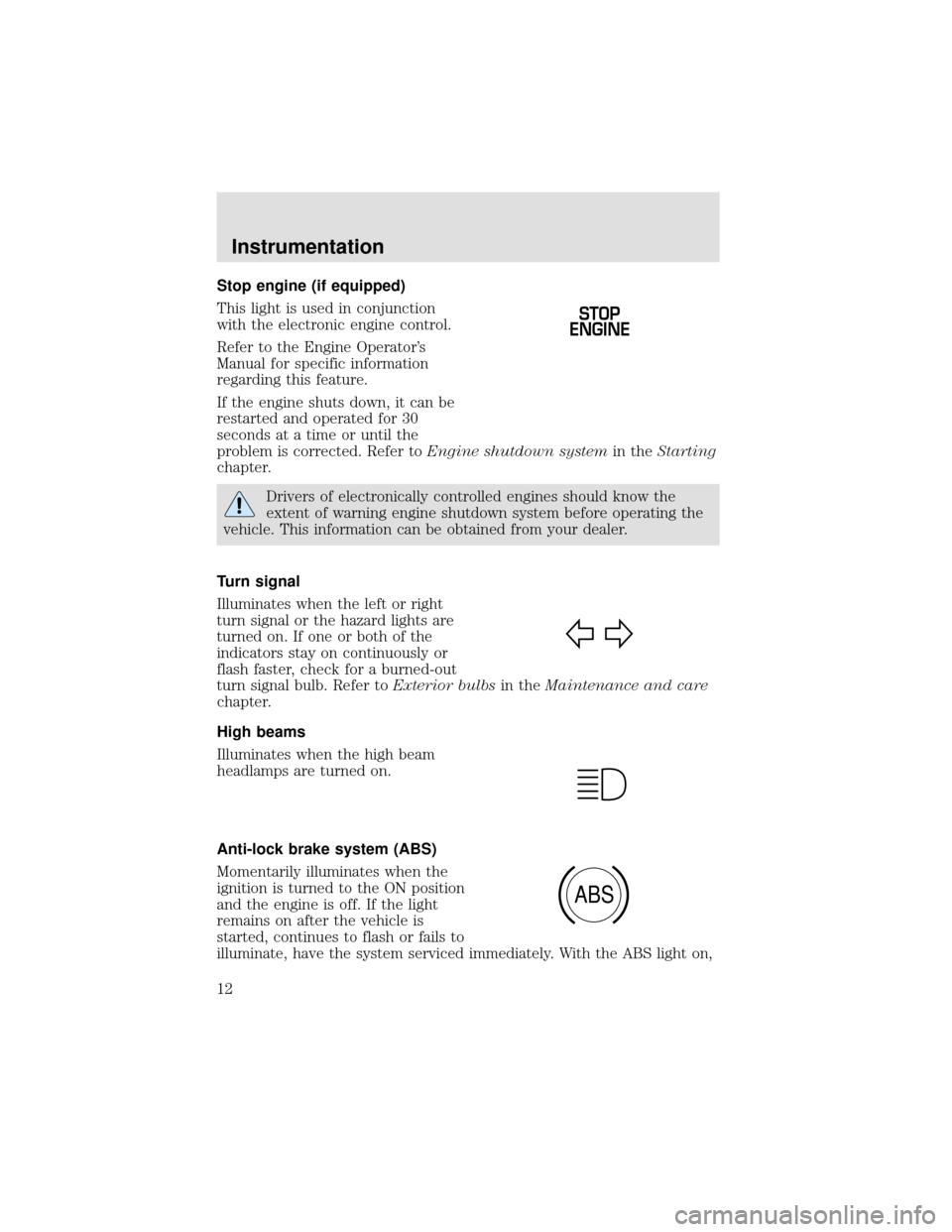
Stop engine (if equipped)
This light is used in conjunction
with the electronic engine control.
Refer to the Engine Operator’s
Manual for specific information
regarding this feature.
If the engine shuts down, it can be
restarted and operated for 30
seconds at a time or until the
problem is corrected. Refer toEngine shutdown systemin theStarting
chapter.
Drivers of electronically controlled engines should know the
extent of warning engine shutdown system before operating the
vehicle. This information can be obtained from your dealer.
Turn signal
Illuminates when the left or right
turn signal or the hazard lights are
turned on. If one or both of the
indicators stay on continuously or
flash faster, check for a burned-out
turn signal bulb. Refer toExterior bulbsin theMaintenance and care
chapter.
High beams
Illuminates when the high beam
headlamps are turned on.
Anti-lock brake system (ABS)
Momentarily illuminates when the
ignition is turned to the ON position
and the engine is off. If the light
remains on after the vehicle is
started, continues to flash or fails to
illuminate, have the system serviced immediately. With the ABS light on,
STOP
ENGINE
ABS
Instrumentation
12
Page 14 of 208
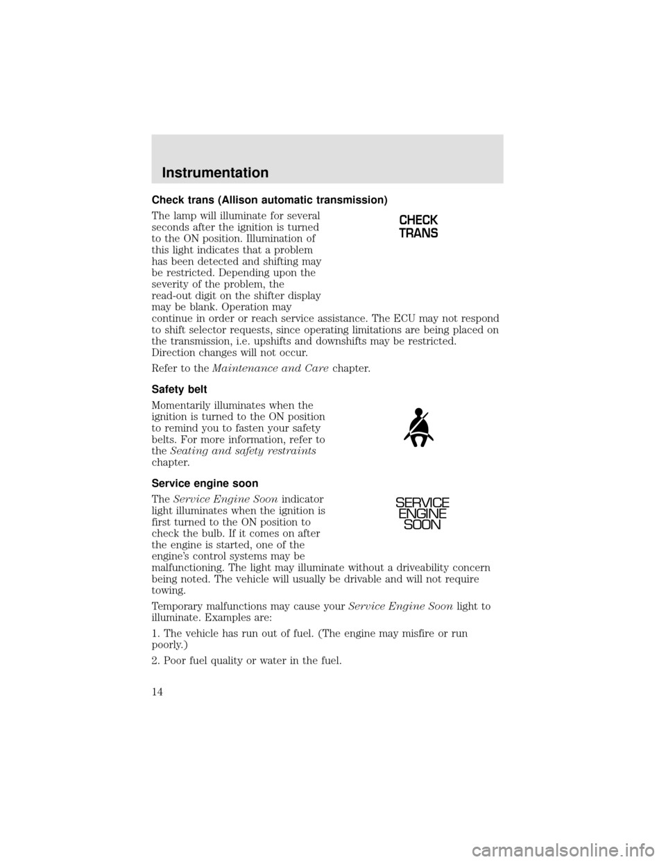
Check trans (Allison automatic transmission)
The lamp will illuminate for several
seconds after the ignition is turned
to the ON position. Illumination of
this light indicates that a problem
has been detected and shifting may
be restricted. Depending upon the
severity of the problem, the
read-out digit on the shifter display
may be blank. Operation may
continue in order or reach service assistance. The ECU may not respond
to shift selector requests, since operating limitations are being placed on
the transmission, i.e. upshifts and downshifts may be restricted.
Direction changes will not occur.
Refer to theMaintenance and Carechapter.
Safety belt
Momentarily illuminates when the
ignition is turned to the ON position
to remind you to fasten your safety
belts. For more information, refer to
theSeating and safety restraints
chapter.
Service engine soon
TheService Engine Soonindicator
light illuminates when the ignition is
first turned to the ON position to
check the bulb. If it comes on after
the engine is started, one of the
engine’s control systems may be
malfunctioning. The light may illuminate without a driveability concern
being noted. The vehicle will usually be drivable and will not require
towing.
Temporary malfunctions may cause yourService Engine Soonlight to
illuminate. Examples are:
1. The vehicle has run out of fuel. (The engine may misfire or run
poorly.)
2. Poor fuel quality or water in the fuel.
CHECK
TRANS
SERVICE
ENGINE
SOON
Instrumentation
14
Page 89 of 208
![FORD F650 2000 10.G Owners Manual When air pressure is insufficient
(below 534 kPa [60 psi]), a warning
light illuminates and a buzzer
sounds when the ignition is in the
ON position.
This condition may be caused by excessive brake app FORD F650 2000 10.G Owners Manual When air pressure is insufficient
(below 534 kPa [60 psi]), a warning
light illuminates and a buzzer
sounds when the ignition is in the
ON position.
This condition may be caused by excessive brake app](/img/11/5066/w960_5066-88.png)
When air pressure is insufficient
(below 534 kPa [60 psi]), a warning
light illuminates and a buzzer
sounds when the ignition is in the
ON position.
This condition may be caused by excessive brake applications depleting
the system air pressure. If this condition occurs, stop driving the vehicle
until the compressor has fully recharged the air system. Do not move the
vehicle in this condition because the brake system may be inoperative.
Select a gear ratio to help slow your vehicle before descending grades.
Supplement with brakes as required to safely slow the vehicle and avoid
overspeeding the engine.
Air chamber stroke indication
All Ford air chamber push rods have orange stroke indicator stripes that
alert the operator when the braking system requires adjustment or
repair. The orange stripe is painted on the air chamber push rod at the
slack adjuster readjustment stroke dimension.
Air brake inspection and adjustment should be performed by a qualified
service technician in accordance with the instructions in the Ford Truck
Service Manual.
Cam brakes—automatic slack adjusters
Standard air brakes (cam) are
equipped with automatic brake
adjusters. Automatic adjustment
occurs during forward and reverse
brake applications. Inspect brakes
for proper adjustment at the
intervals listed in the vehicle Service
Maintenance Guide.
!
BRAKE
Driving
89
Page 105 of 208
These transmissions have no P (Park) position. Before leaving
the driver’s seat, always shift into N (Neutral) and set the
parking brake. Shut the engine off and remove your ignition key.
Always use wheel chocks for hilly or off-road parking. Unexpected and
possibly sudden vehicle movement may occur if these precautions are
not taken.
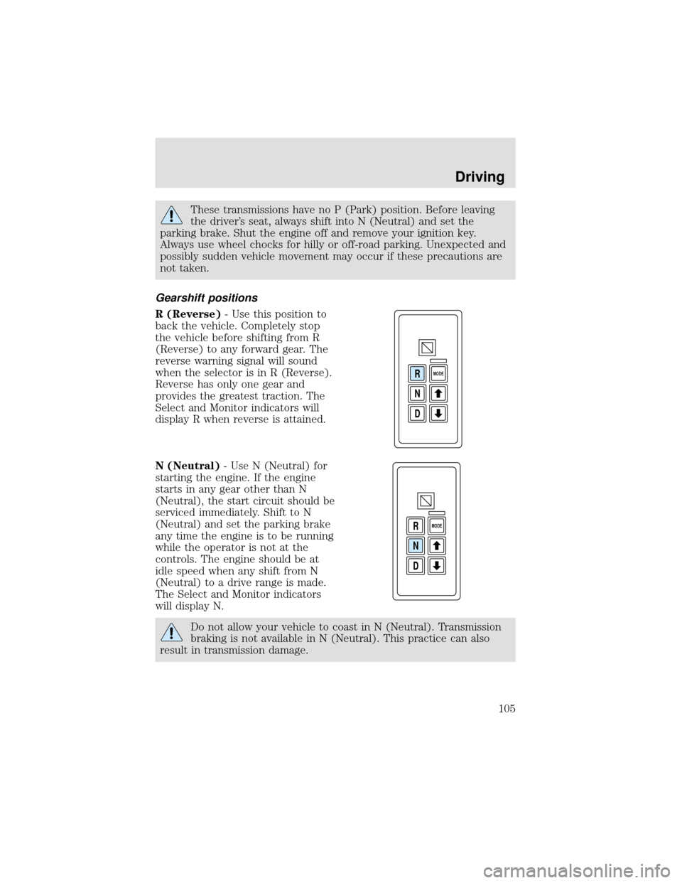
Gearshift positions
R (Reverse)- Use this position to
back the vehicle. Completely stop
the vehicle before shifting from R
(Reverse) to any forward gear. The
reverse warning signal will sound
when the selector is in R (Reverse).
Reverse has only one gear and
provides the greatest traction. The
Select and Monitor indicators will
display R when reverse is attained.
N (Neutral)- Use N (Neutral) for
starting the engine. If the engine
starts in any gear other than N
(Neutral), the start circuit should be
serviced immediately. Shift to N
(Neutral) and set the parking brake
any time the engine is to be running
while the operator is not at the
controls. The engine should be at
idle speed when any shift from N
(Neutral) to a drive range is made.
The Select and Monitor indicators
will display N.
Do not allow your vehicle to coast in N (Neutral). Transmission
braking is not available in N (Neutral). This practice can also
result in transmission damage.
D N R
MODE
D N R
MODE
Driving
105
Page 128 of 208
1. Start the engine and let it run until it reaches normal operating
temperature (the engine coolant temperature gauge indicator will be
near the center of the normal area between H and C).
2. Park the vehicle on level ground.
3. Set the parking brake and shift into N (Neutral) (automatic
transmission) or 1 (First) (manual transmission).
4. Turn off the engine and wait a few minutes for the oil to drain
completely into the oil pan.
5. Open the hood. Protect yourself from engine heat.
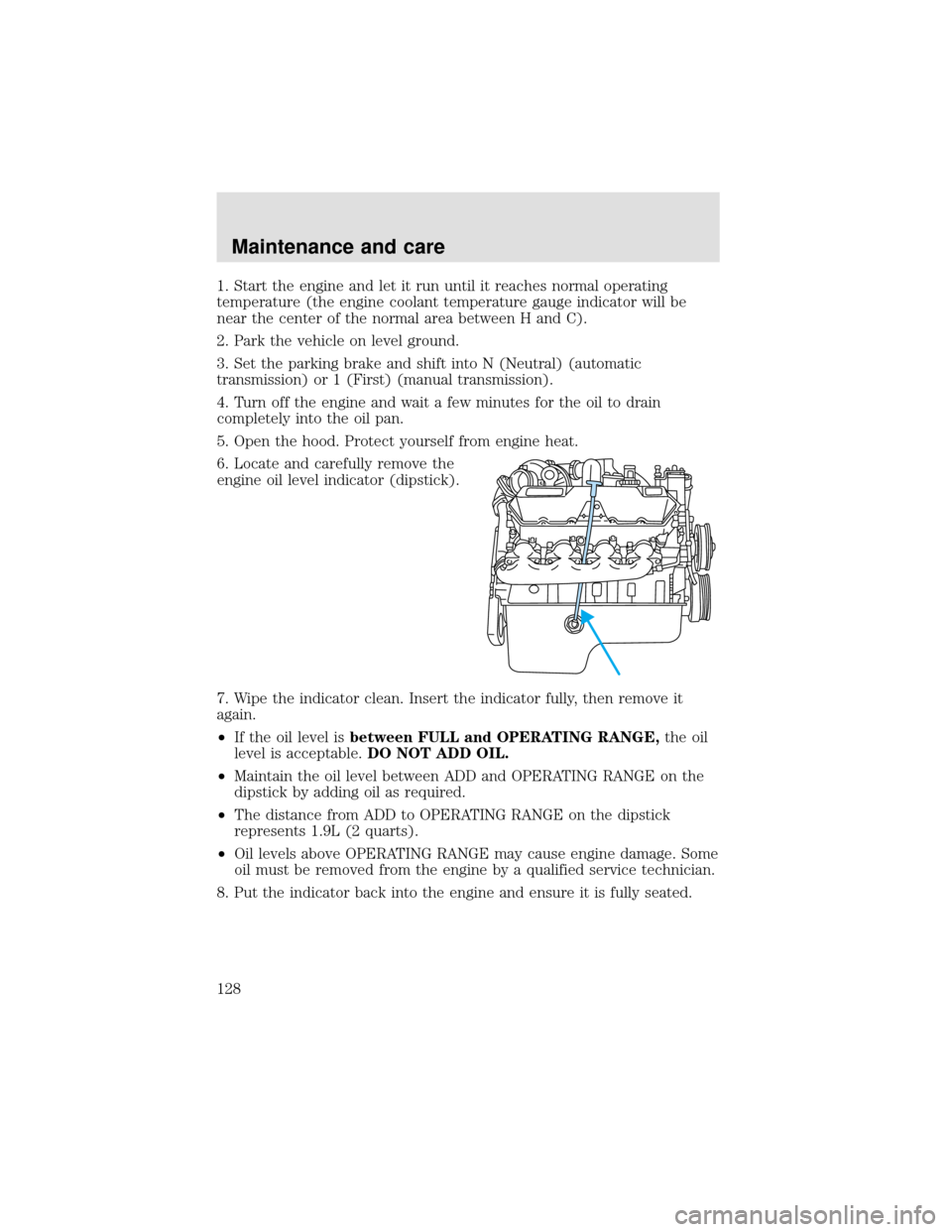
6. Locate and carefully remove the
engine oil level indicator (dipstick).
7. Wipe the indicator clean. Insert the indicator fully, then remove it
again.
•If the oil level isbetween FULL and OPERATING RANGE,the oil
level is acceptable.DO NOT ADD OIL.
•Maintain the oil level between ADD and OPERATING RANGE on the
dipstick by adding oil as required.
•The distance from ADD to OPERATING RANGE on the dipstick
represents 1.9L (2 quarts).
•Oil levels above OPERATING RANGE may cause engine damage. Some
oil must be removed from the engine by a qualified service technician.
8. Put the indicator back into the engine and ensure it is fully seated.
Maintenance and care
128
Page 141 of 208
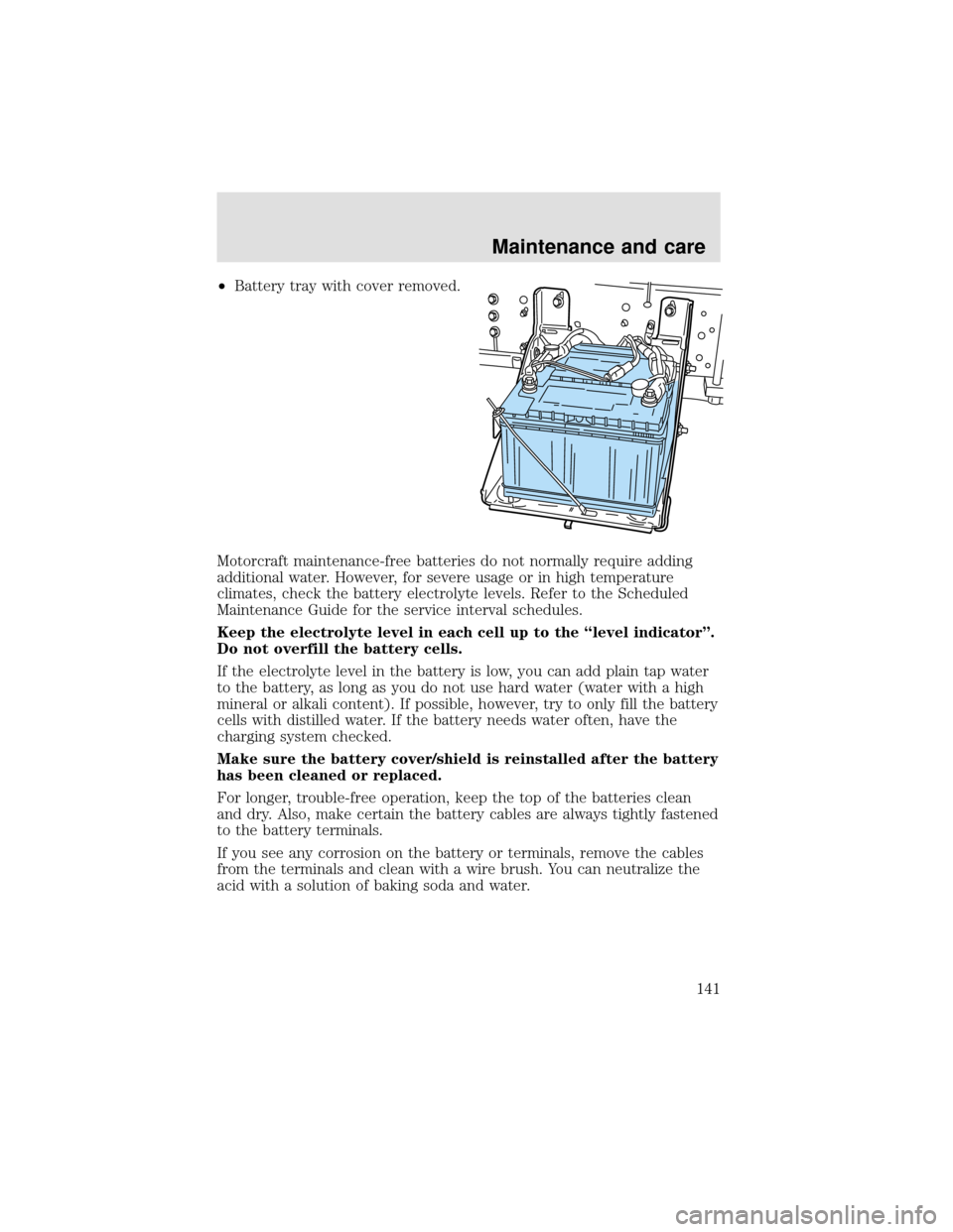
•Battery tray with cover removed.
Motorcraft maintenance-free batteries do not normally require adding
additional water. However, for severe usage or in high temperature
climates, check the battery electrolyte levels. Refer to the Scheduled
Maintenance Guide for the service interval schedules.
Keep the electrolyte level in each cell up to the “level indicator”.
Do not overfill the battery cells.
If the electrolyte level in the battery is low, you can add plain tap water
to the battery, as long as you do not use hard water (water with a high
mineral or alkali content). If possible, however, try to only fill the battery
cells with distilled water. If the battery needs water often, have the
charging system checked.
Make sure the battery cover/shield is reinstalled after the battery
has been cleaned or replaced.
For longer, trouble-free operation, keep the top of the batteries clean
and dry. Also, make certain the battery cables are always tightly fastened
to the battery terminals.
If you see any corrosion on the battery or terminals, remove the cables
from the terminals and clean with a wire brush. You can neutralize the
acid with a solution of baking soda and water.
Maintenance and care
141
Page 142 of 208
Batteries normally produce explosive gases which can cause
personal injury. Therefore, do not allow flames, sparks or lighted
substances to come near the battery. When working near the battery,
always shield your face and protect your eyes. Always provide proper
ventilation.
When lifting a plastic-cased battery, excessive pressure on the
end walls could cause acid to flow through the vent caps,
resulting in personal injury and/or damage to the vehicle or battery.
Lift the battery with a battery carrier or with your hands on opposite
corners.
Keep batteries out of reach of children. Batteries contain sulfuric
acid. Avoid contact with skin, eyes or clothing. Shield your eyes
when working near the battery to protect against possible splashing of
acid solution. In case of acid contact with skin or eyes, flush
immediately with water for a minimum of 15 minutes and get prompt
medical attention. If acid is swallowed, call a physician immediately.
AIR FILTER
When to service
Your vehicle is equipped with an air filter restriction gauge to determine
when to replace the air filter element. It is not possible to determine the
need for service by visually inspecting the air filter.
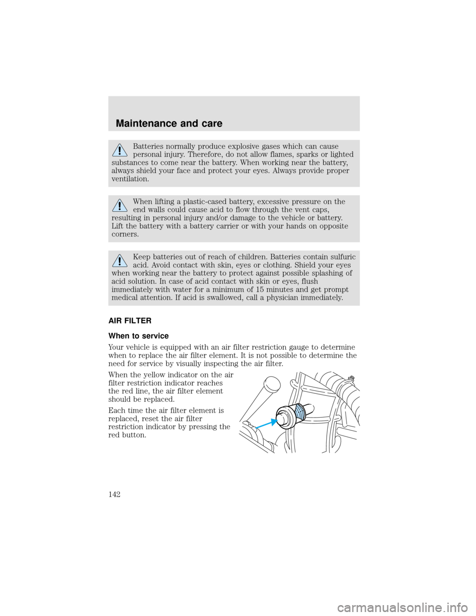
When the yellow indicator on the air
filter restriction indicator reaches
the red line, the air filter element
should be replaced.
Each time the air filter element is
replaced, reset the air filter
restriction indicator by pressing the
red button.
Maintenance and care
142
Page 146 of 208
10. Reset the air filter restriction indicator.
11. Inspect the air induction system for loose fitting, damaged or missing
components and repair as necessary.
WINDSHIELD WIPER BLADES
Check the wiper blades at least twice a year or when they seem less
effective. Substances such as tree sap and some hot wax treatments used
by commercial car washes reduce the effectiveness of wiper blades.
Checking the wiper blades
If the wiper blades do not wipe properly, clean both the windshield and
wiper blades using undiluted windshield wiper solution or a mild
detergent. Rinse thoroughly with clean water. To avoid damaging the
blades, do not use fuel, kerosene, paint thinner or other solvents.
Changing the wiper blades
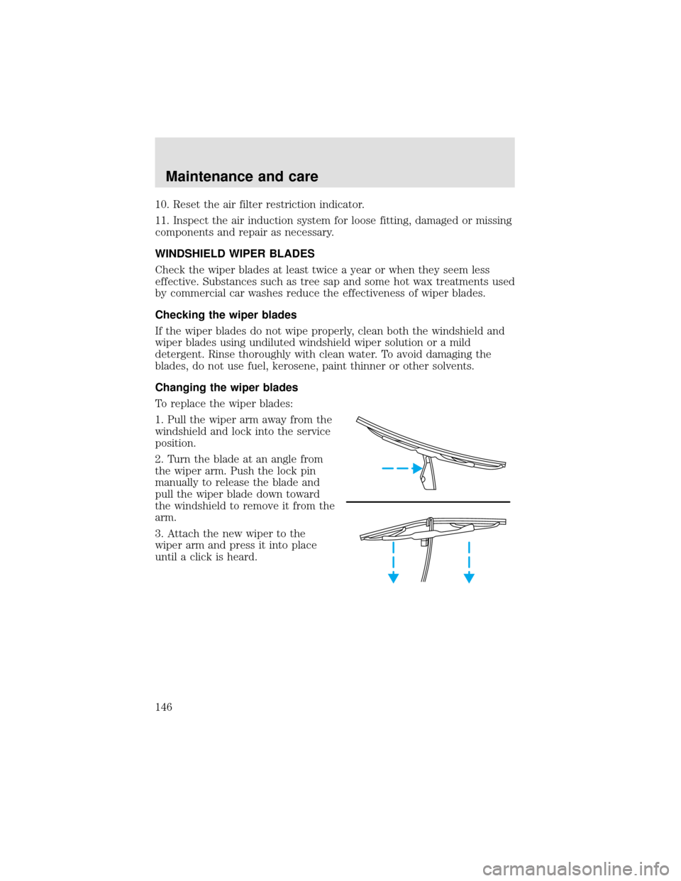
To replace the wiper blades:
1. Pull the wiper arm away from the
windshield and lock into the service
position.
2. Turn the blade at an angle from
the wiper arm. Push the lock pin
manually to release the blade and
pull the wiper blade down toward
the windshield to remove it from the
arm.
3. Attach the new wiper to the
wiper arm and press it into place
until a click is heard.
Maintenance and care
146
Page 176 of 208
OWNER MAINTENANCE
You can do much of the maintenance your vehicle requires yourself, if
you have the time and a reasonable amount of mechanical ability. If you
prefer to have this work done professionally, your authorized dealer
stands ready to help you.
All mechanical components and attachments are important in that they
could affect the performance of vital components and systems. If
replacement becomes necessary, they must be replaced with parts having
the same part number or with equivalent parts. Torque values of the
attaching parts must be used as specified during any reassembly
procedure to assure proper retention.
EMISSIONS CONTROL SYSTEM
To assure the emissions control systems operate effectively, you should
have the services listed in the maintenance schedule performed at the
specified time and km/mileage intervals. You should avoid running out of
fuel or turning off the ignition while the vehicle is in motion, especially
at high speeds.
Because of high engine compartment and exhaust system
temperatures resulting from emissions equipment, do not park,
idle or operate your vehicle in dry grass or other dry ground cover
where the possibility of ground fire exists.
Do not make unauthorized modifications to the engine or vehicle.
Modifications causing increased amounts of unburned fuel to reach the
exhaust system can significantly increase the temperature of the engine
compartment and/or the exhaust system.
Avoid driving your vehicle if it does not operate properly. If the engine
diesels (more than five seconds of engine run-on after shut-off), misfires,
surges, stalls or backfires, see your dealer. Be alert for fluid leakage,
odor, smoke, loss of oil pressure, or charge indicator or over temperature
warning.
Do NOT use diesel fuel blended with waste oil in engines equipped with
a CATALYTIC CONVERTER-MUFFLER. Waste lube oil blending in fuel
will plug the CATALYTIC CONVERTER-MUFFLER, resulting in a
significant loss of engine power.
General maintenance information
176
Page 179 of 208

SCHEDULED MAINTENANCE SERVICES
Maintenance service adjustments must conform to specifications
contained in this manual, and those shown on the Important Engine
Information Decal. The following services are to be performed at
scheduled intervals because they are considered essential to the life and
performance of your vehicle. Ford recommends that you perform
maintenance on all designated items to achieve best vehicle operation.
Scheduled maintenance beyond 160 930 km (100 000 miles) should be
continued as before 160 930 km (100 000 miles).
SPECIAL OPERATING CONDITIONS
If your driving habitsfrequentlyinclude one or more the following
conditions:
•Short trips oflessthan 16 km (ten miles) when outside temperatures
remain below freezing.
•Operating duringhot weatherin stop-and-go“rush hour”traffic.
•Operating in severe dust conditions.
•Extensive idling, or low speed operation such as door-to-door delivery
service.
•High speed operation with a fully loaded vehicle (max. GVW).
•Snowplowing.
Perform the following:
•Change engine oil and oil filter every three months, 8 000 km (5 000
miles) or 125 hours of engine service.
•If operating in severe dust conditions, replace the air cleaner filter
more often than regular intervals as determined by the air filter
restriction indicator. Make sure that the air filter restriction indicator
is in good working order.
•Lube the manual transmission and the rear axle every 48 279 km
(30 000 miles) or 6 months, whichever comes first.
•See the Allison, Cummins and Caterpillar Operator’s Manual.
General maintenance information
179