check engine light FORD F650 2002 10.G Owners Manual
[x] Cancel search | Manufacturer: FORD, Model Year: 2002, Model line: F650, Model: FORD F650 2002 10.GPages: 256, PDF Size: 1.75 MB
Page 12 of 256
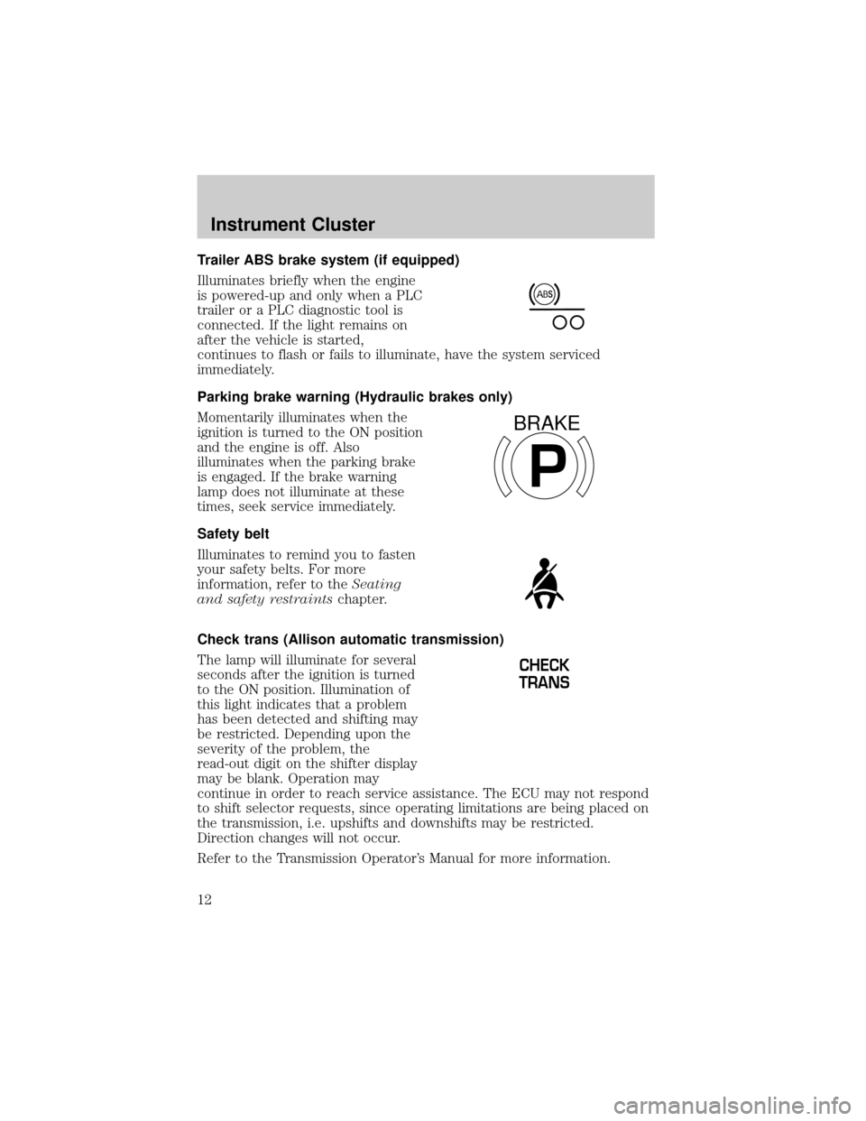
Trailer ABS brake system (if equipped)
Illuminates briefly when the engine
is powered-up and only when a PLC
trailer or a PLC diagnostic tool is
connected. If the light remains on
after the vehicle is started,
continues to flash or fails to illuminate, have the system serviced
immediately.
Parking brake warning (Hydraulic brakes only)
Momentarily illuminates when the
ignition is turned to the ON position
and the engine is off. Also
illuminates when the parking brake
is engaged. If the brake warning
lamp does not illuminate at these
times, seek service immediately.
Safety belt
Illuminates to remind you to fasten
your safety belts. For more
information, refer to theSeating
and safety restraintschapter.
Check trans (Allison automatic transmission)
The lamp will illuminate for several
seconds after the ignition is turned
to the ON position. Illumination of
this light indicates that a problem
has been detected and shifting may
be restricted. Depending upon the
severity of the problem, the
read-out digit on the shifter display
may be blank. Operation may
continue in order to reach service assistance. The ECU may not respond
to shift selector requests, since operating limitations are being placed on
the transmission, i.e. upshifts and downshifts may be restricted.
Direction changes will not occur.
Refer to the Transmission Operator's Manual for more information.
P
BRAKE
CHECK
TRANS
Instrument Cluster
12
Page 14 of 256
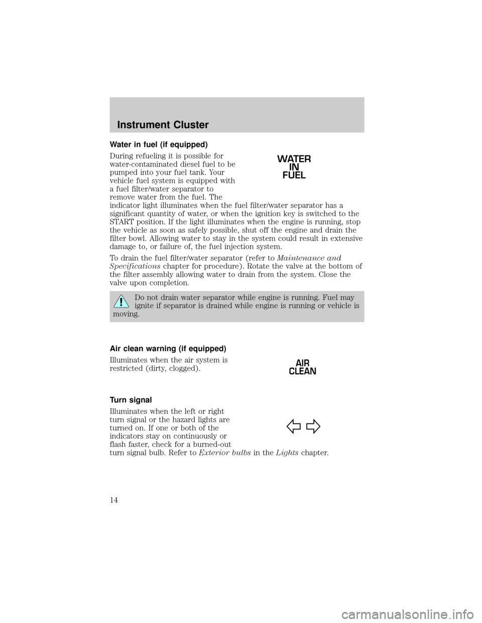
Water in fuel (if equipped)
During refueling it is possible for
water-contaminated diesel fuel to be
pumped into your fuel tank. Your
vehicle fuel system is equipped with
a fuel filter/water separator to
remove water from the fuel. The
indicator light illuminates when the fuel filter/water separator has a
significant quantity of water, or when the ignition key is switched to the
START position. If the light illuminates when the engine is running, stop
the vehicle as soon as safely possible, shut off the engine and drain the
filter bowl. Allowing water to stay in the system could result in extensive
damage to, or failure of, the fuel injection system.
To drain the fuel filter/water separator (refer toMaintenance and
Specificationschapter for procedure). Rotate the valve at the bottom of
the filter assembly allowing water to drain from the system. Close the
valve upon completion.
Do not drain water separator while engine is running. Fuel may
ignite if separator is drained while engine is running or vehicle is
moving.
Air clean warning (if equipped)
Illuminates when the air system is
restricted (dirty, clogged).
Turn signal
Illuminates when the left or right
turn signal or the hazard lights are
turned on. If one or both of the
indicators stay on continuously or
flash faster, check for a burned-out
turn signal bulb. Refer toExterior bulbsin theLightschapter.
WATER
IN
FUEL
AIR
CLEAN
Instrument Cluster
14
Page 17 of 256
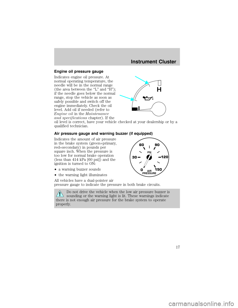
Engine oil pressure gauge
Indicates engine oil pressure. At
normal operating temperature, the
needle will be in the normal range
(the area between the ªLº and ªHº);
if the needle goes below the normal
range, stop the vehicle as soon as
safely possible and switch off the
engine immediately. Check the oil
level. Add oil if needed (refer to
Engine oilin theMaintenance
and specificationschapter). If the
oil level is correct, have your vehicle checked at your dealership or by a
qualified technician.
Air pressure gauge and warning buzzer (if equipped)
Indicates the amount of air pressure
in the brake system (green=primary,
red=secondary) in pounds per
square inch. When the pressure is
too low for normal brake operation
(less than 414 kPa [60 psi]) and the
ignition is turned to ON:
²a warning buzzer sounds
²the warning light illuminates
All vehicles have a dual-pointer air
pressure gauge to indicate the pressure in both brake circuits.
Do not drive the vehicle when the low air pressure buzzer is
sounding or the warning light is lit. These warnings indicate
there is not enough air pressure for the brake system to operate
properly.
L
H
0 30120 90 60
150AIR
PRESSURE
PSI
Instrument Cluster
17
Page 120 of 256
Air brakes
After starting the engine, give the air compressor time to build up the air
pressure to 414 kPa (60 psi) before moving the vehicle.
Do not drive or continue to drive if the low air pressure buzzer
is sounding or the brake warning light is lit. These warnings
indicate that air pressure is not to normal operating level. Continued
use of the vehicle could result in loss of braking ability.
Avoid repeated light application of the brake pedal. This will
deplete air pressure faster and could result in loss of braking
capability.
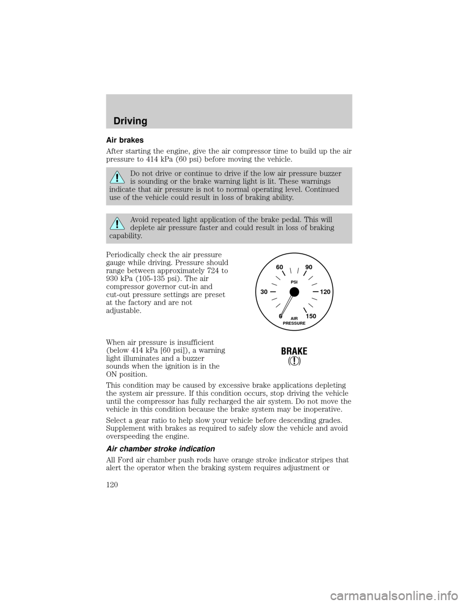
Periodically check the air pressure
gauge while driving. Pressure should
range between approximately 724 to
930 kPa (105-135 psi). The air
compressor governor cut-in and
cut-out pressure settings are preset
at the factory and are not
adjustable.
When air pressure is insufficient
(below 414 kPa [60 psi]), a warning
light illuminates and a buzzer
sounds when the ignition is in the
ON position.
This condition may be caused by excessive brake applications depleting
the system air pressure. If this condition occurs, stop driving the vehicle
until the compressor has fully recharged the air system. Do not move the
vehicle in this condition because the brake system may be inoperative.
Select a gear ratio to help slow your vehicle before descending grades.
Supplement with brakes as required to safely slow the vehicle and avoid
overspeeding the engine.
Air chamber stroke indication
All Ford air chamber push rods have orange stroke indicator stripes that
alert the operator when the braking system requires adjustment or
0 30 12090 60
150AIR
PRESSUREPSI
!
BRAKE
Driving
120
Page 134 of 256
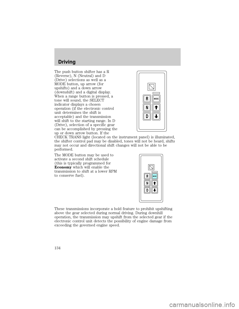
The push button shifter has a R
(Reverse), N (Neutral) and D
(Drive) selections as well as a
MODE button, up arrow (for
upshifts) and a down arrow
(downshift) and a digital display.
When a range button is pressed, a
tone will sound, the SELECT
indicator displays a chosen
operation (if the electronic control
unit determines the shift is
acceptable) and the transmission
will shift to the starting range. In D
(Drive), selection of a specific gear
can be accomplished by pressing the
up or down arrow button. If the
CHECK TRANS light (located on the instrument panel) is illuminated,
the shifter control pad may be disabled, tones will not be heard, shifts
may not occur and directional shift changes will not be able to be
performed.
The MODE button may be used to
activate a second shift schedule
(this is typically programmed for
Economywhich will enable the
transmission to shift at a lower RPM
to conserve fuel).
These transmissions incorporate a hold feature to prohibit upshifting
above the gear selected during normal driving. During downhill
operation, the transmission may upshift from the selected gear if the
electronic control unit detects the possibility of engine damage from
exceeding the governed engine speed.
D N R
MODE
D N R
MODE
Driving
134
Page 192 of 256
²Do not add extra inhibitors or additives to the coolant.These
can be harmful and compromise the corrosion protection of the engine
coolant.
²Do not mix with recycled coolant unless from a Ford-approved
recycling process (seeUse of Recycled Engine Coolantsection).
For vehicles with overflow coolant systems with a non-pressurized cap
on the coolant recovery system, add coolant to the coolant recovery
reservoir when the engine is cool. Add the proper mixture of coolant and
water to the ªcold fullº level. For all other vehicles, which have a coolant
degas system with a pressurized cap, or if it is necessary to remove the
coolant pressure relief cap on the radiator of a vehicle with an overflow
system, follow these steps to add engine coolant.
To avoid personal injury, make sure the engine is cool before
unscrewing the coolant pressure relief cap. The cooling system is
under pressure; steam and hot liquid can come out forcefully when the
cap is loosened slightly.
1. Before you begin, turn the engine off and let it cool.
2. When the engine is cool, wrap a thick cloth around the coolant
pressure relief cap on the coolant reservoir (an opaque plastic bottle).
Slowly turn cap counterclockwise (left) until pressure begins to release.
3. Step back while the pressure releases.
4. When you are sure that all the pressure has been released, use the
cloth to turn it counterclockwise and remove the cap.
5. Fill the coolant reservoir slowly with the proper coolant mixture (see
above), to within the ªcold fill rangeº or the ªcold fullº level on the
reservoir. If you removed the radiator cap in an overflow system, fill the
radiator until the coolant is visible and radiator is almost full.
6. Replace the cap. Turn until tightly installed. (Cap must be tightly
installed to prevent coolant loss.)
After any coolant has been added, check the coolant concentration see
Checking Engine Coolant section). If the concentration is not 50/50
(protection to ±34É F/±36É C), drain some coolant and adjust the
concentration. It may take several drains and additions to obtain a 50/50
coolant concentration.
Whenever coolant has been added, the coolant level in the coolant
reservoir should be checked the next few times you drive the vehicle. If
Maintenance and Specifications
192
Page 237 of 256
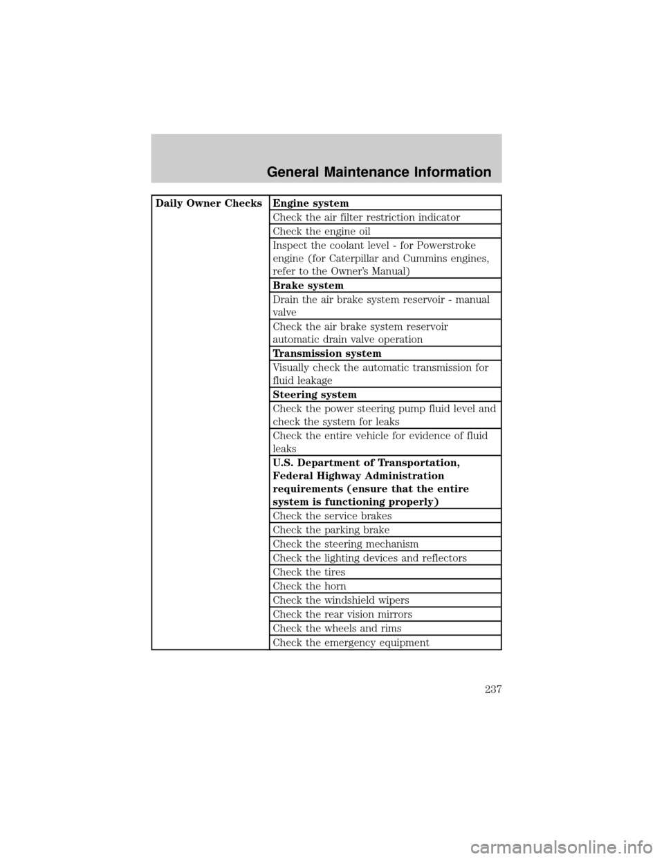
Daily Owner Checks Engine system
Check the air filter restriction indicator
Check the engine oil
Inspect the coolant level - for Powerstroke
engine (for Caterpillar and Cummins engines,
refer to the Owner's Manual)
Brake system
Drain the air brake system reservoir - manual
valve
Check the air brake system reservoir
automatic drain valve operation
Transmission system
Visually check the automatic transmission for
fluid leakage
Steering system
Check the power steering pump fluid level and
check the system for leaks
Check the entire vehicle for evidence of fluid
leaks
U.S. Department of Transportation,
Federal Highway Administration
requirements (ensure that the entire
system is functioning properly)
Check the service brakes
Check the parking brake
Check the steering mechanism
Check the lighting devices and reflectors
Check the tires
Check the horn
Check the windshield wipers
Check the rear vision mirrors
Check the wheels and rims
Check the emergency equipment
General Maintenance Information
237
Page 249 of 256

A
Air cleaner filter .......................211
Air conditioning
manual heating and air
conditioning system .................57
Audio system
(see Radio) ..........20, 25, 31, 39±40
Automatic transmission ............132
Auxiliary power point .................73
B
Battery .......................................187
jumping a disabled battery ....164
voltage gauge ............................18
BeltMinder ...................................98
Brakes ................................113, 119
anti-lock ...................114±115, 121
anti-lock brake system
(ABS) warning light ...11±12, 114
brake warning light ............11±12
fluid, checking and adding ....208
parking ....................115, 118, 122
trailer .......................................124
C
CD-6 disc .....................................40
CD-single premium .....................31
Child safety restraints ..............102
child safety belts ....................102
Child safety seats ......................103
attaching with tether straps ..107
in front seat ............................105
in rear seat ..............................105
tether anchorage hardware ...107Cleaning your vehicle
engine compartment ..............176
exterior ....................................179
instrument cluster lens ..........178
instrument panel ....................177
interior .....................................178
plastic parts ............176±177, 179
safety belts ..............................179
washing ....................................174
waxing .....................................174
wheels ......................................175
windows ..................................179
wiper blades ............................177
Climate control (see Air
conditioning or Heating) ......56±57
Clock ..........................23, 28, 36, 44
Clutch ........................................207
fluid ..........................................206
Compass, electronic ....................70
calibration .................................72
set zone adjustment .................71
Console
overhead ....................................70
Controls
power seat .................................90
Coolant ......................................189
refill capacities ........................194
Cruise control (see Speed
control) ........................................77
Customer Assistance ................150
Ford accessories for your
vehicle .....................................180
Getting assistance outside
the U.S. and Canada ..............170
Getting roadside assistance ...150
Getting the service
you need .................................165
Index
249
Page 250 of 256

Ordering additional owner's
literature .................................171
The Dispute Settlement
Board .......................................167
D
Daytime running lamps
(see Lamps) ................................61
Driving under special
conditions
through water .........................148
E
Emergencies, roadside
jump-starting ..........................164
Emission control system ..........231
Engine
check engine/service engine
soon light ....................................9
cleaning ...................................176
coolant .....................................189
Engine block heater .................110
Engine fan .................................195
Engine oil ..................................183
checking and adding ..............183
oil pressure gauge ....................17
recommendations ...................184
Exhaust fumes ..........................112
F
Foglamps .....................................62
Fuel ............................................196
calculating fuel
economy ..........................202, 204
choosing the right fuel ...........197
filling your vehicle with fuel ..196filter, specifications ........198±200
gauge .........................................18
improving fuel
economy ..........................202, 204
safety information relating to
automotive fuels .....................196
Fuses ..................................151±152
G
Gas mileage
(see Fuel economy) .........202, 204
Gauges .........................................16
battery voltage gauge ...............18
engine coolant temperature
gauge .........................................16
engine oil pressure gauge ........17
fuel gauge ..................................18
odometer ...................................19
speedometer .............................18
tachometer ................................19
trip odometer ............................19
H
Hazard flashers .........................150
Headlamps ...................................61
aiming ........................................62
daytime running lights .............61
flash to pass ..............................61
high beam ...........................15, 61
turning on and off ....................61
warning chime ..........................15
Heating
heater only system ...................56
heating and air conditioning
system .......................................57
Index
250
Page 251 of 256

I
Ignition
removing the key ....................145
Infant seats
(see Safety seats) .....................103
Instrument panel
cleaning ...................................177
cluster ......................................178
lighting up panel and
interior .......................................62
J
Jump-starting your vehicle ......164
K
Keys
key in ignition chime ...............15
removing from the ignition ....145
L
Lamps ..........................................73
bulb replacement
specifications chart ..................64
cargo lamps ...............................62
daytime running light ...............61
fog lamps ...................................62
headlamps .................................61
headlamps, flash to pass ..........61
instrument panel, dimming .....62
interior lamps ...........................63
replacing bulbs ...................63±67
Lane change indicator
(see Turn signal) ........................63
Lights, warning and
indicator ..................................9, 14anti-lock brakes
(ABS) ..........................11±12, 114
brake ....................................11±12
charging system ........................13
check coolant ......................12±13
high beam .................................15
safety belt .................................12
service engine soon ....................9
turn signal indicator .................14
Lubricant specifications ...........222
M
Maintenance and Care ..............233
Manual transmission .................141
Mirrors .........................................75
heated ........................................73
side view mirrors (power) .......76
O
Odometer .....................................19
P
Panic alarm feature, remote
entry system ................................85
Parking brake ............115, 118, 122
Power distribution box
(see Fuses) ...............................155
Power door locks ........................84
Power mirrors .............................76
Power steering ..................130±131
fluid, checking and adding ....205
Power Windows ...........................74
Index
251