AUX FORD F650 2005 11.G Owners Manual
[x] Cancel search | Manufacturer: FORD, Model Year: 2005, Model line: F650, Model: FORD F650 2005 11.GPages: 272, PDF Size: 1.5 MB
Page 54 of 272
Never adjust the steering wheel when the vehicle is moving.
AUXILIARY POWER POINT
Power points are designed for
accessory plugs only. Do not
hang any type of accessory or
accessory bracket from the plug.
Improper use of the power point
can cause damage not covered
by your warranty.
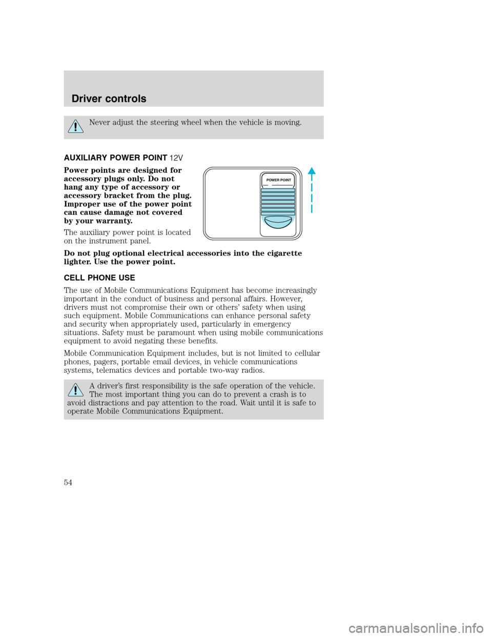
The auxiliary power point is located
on the instrument panel.
Do not plug optional electrical accessories into the cigarette
lighter. Use the power point.
CELL PHONE USE
The use of Mobile Communications Equipment has become increasingly
important in the conduct of business and personal affairs. However,
drivers must not compromise their own or others’safety when using
such equipment. Mobile Communications can enhance personal safety
and security when appropriately used, particularly in emergency
situations. Safety must be paramount when using mobile communications
equipment to avoid negating these benefits.
Mobile Communication Equipment includes, but is not limited to cellular
phones, pagers, portable email devices, in vehicle communications
systems, telematics devices and portable two-way radios.
A driver’s first responsibility is the safe operation of the vehicle.
The most important thing you can do to prevent a crash is to
avoid distractions and pay attention to the road. Wait until it is safe to
operate Mobile Communications Equipment.
POWER POINT
Driver controls
54
Page 56 of 272
Window lock (if equipped)
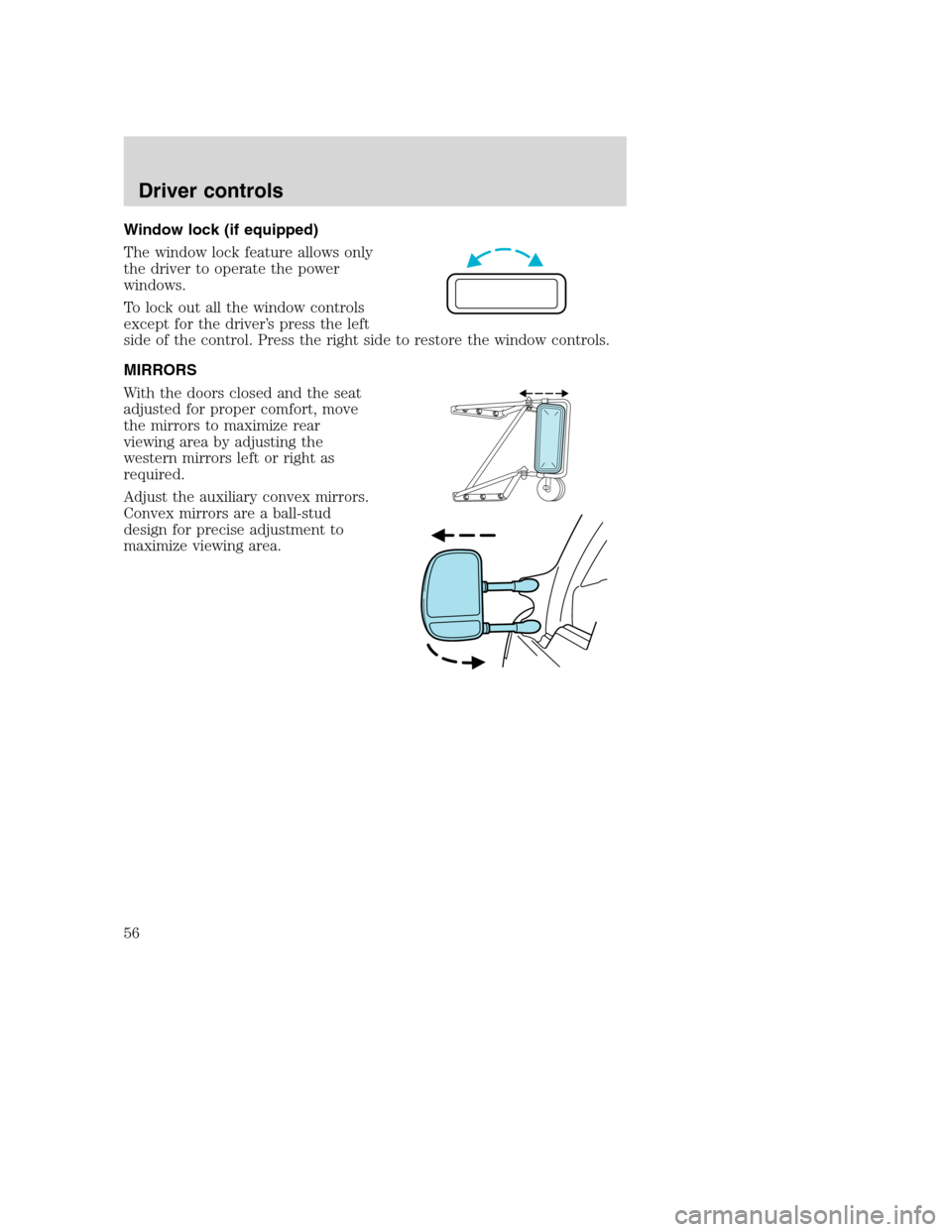
The window lock feature allows only
the driver to operate the power
windows.
To lock out all the window controls
except for the driver’s press the left
side of the control. Press the right side to restore the window controls.
MIRRORS
With the doors closed and the seat
adjusted for proper comfort, move
the mirrors to maximize rear
viewing area by adjusting the
western mirrors left or right as
required.
Adjust the auxiliary convex mirrors.
Convex mirrors are a ball-stud
design for precise adjustment to
maximize viewing area.
Driver controls
56
Page 105 of 272
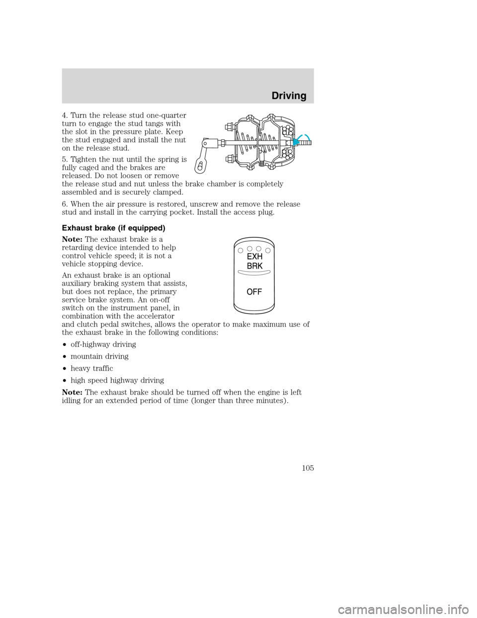
4. Turn the release stud one-quarter
turn to engage the stud tangs with
the slot in the pressure plate. Keep
the stud engaged and install the nut
on the release stud.
5. Tighten the nut until the spring is
fully caged and the brakes are
released. Do not loosen or remove
the release stud and nut unless the brake chamber is completely
assembled and is securely clamped.
6. When the air pressure is restored, unscrew and remove the release
stud and install in the carrying pocket. Install the access plug.
Exhaust brake (if equipped)
Note:The exhaust brake is a
retarding device intended to help
control vehicle speed; it is not a
vehicle stopping device.
An exhaust brake is an optional
auxiliary braking system that assists,
but does not replace, the primary
service brake system. An on-off
switch on the instrument panel, in
combination with the accelerator
and clutch pedal switches, allows the operator to make maximum use of
the exhaust brake in the following conditions:
•off-highway driving
•mountain driving
•heavy traffic
•high speed highway driving
Note:The exhaust brake should be turned off when the engine is left
idling for an extended period of time (longer than three minutes).
Driving
105
Page 108 of 272

•Depending on the grade and vehicle load, you may or may not feel the
retarding force acting against your body when the brake is applied.
The brake’s retarding force is actually preventing the vehicle from
going much faster.
•Engine speed has a major effect on retarding performance, with higher
engine speeds permitting greater retarding ability.
•Engine brake performance is closely related to the type of
transmission your vehicle is equipped with. Downshifting of manual
transmission to the lowest gear possible, without exceeding the
maximum engine RPM limit, will maximize retarding performance.
Exhaust brakes will operate effectively with automatic transmissions,
but performance will vary with engine speed and the gear selected by
the transmission.
Make sure the exhaust brake is turned off before shutting off the engine.
Note:Installing an exhaust or auxiliary brake does not necessarily
protect the engine from exceeding maximum governed speed. The
primary brakes should be used to never allow the engine to exceed
maximum governed speed under any conditions.
Trailer brake hand control (if equipped)
The hand control, located on the
right-hand side of the instrument
panel, is used to apply the trailer
service brakes which are
independent of the truck or tractor
service brakes.
The hand control should
never be used to apply the
brakes when the tractor and
trailer are parked unattended. Air
may leak from the system and the
vehicle could possibly move,
resulting in possible property
damage, personal injury or death.
The hand control operates a valve that provides gradual control of air
pressure applied; when the valve is only partially applied, the trailer
brakes can be overridden by pressing fully on the brake pedal.
Driving
108
Page 118 of 272
9. Charge the trailer brake system. Set the trailer brakes, either with the
hand valve or tractor protection valve. Pull against the trailer for an
additional check of proper hook-up. Do not pull hard enough to damage
or strain the equipment.
10. Set the tractor parking brakes and fully raise the trailer landing gear.
Refer toBrakesin this chapter for proper operation of the parking brake
and trailer brakes.
11. Check the operation of all trailer lights and correct any lights that
may be faulty.
Un-hook
1. Try to keep the tractor and trailer in a straight line.
2. Apply the parking brakes.
3. Lower the trailer landing gear, making sure it is on solid, level ground.
The weight of the trailer is to be on the landing gear.
4. Block the trailer wheels.
5. Disconnect the brake hoses and light cords. Be sure hoses and cords
are clear.
6. Pull coupler release lever to disengage the fifth wheel jaws.
7. Release the tractor parking brakes.
8. Pull out from the trailer slowly, allowing the landing gear to take the
load gradually.
AUTOMATIC TRANSMISSION OPERATION (IF EQUIPPED)
Main transmission, auxiliary transmission, transfer case and power
take-off (PTO) control shift patterns can be found on a placard or decal
on the driver’s sun visor, on the instrument panel or on the shift control
itself.
The main transmission control is used to select the various gear ratios or
speeds of the transmission. Selecting D (Direct Drive), does not change
the transmission gear ratio, but is used where the gear ratios in the main
transmission are adequate to handle the vehicle operation.
Hold the brake pedal down while you move the gearshift lever
between positions. If you don’t hold the brake pedal down, your
vehicle may move unexpectedly and cause property damage, personal
injury or death.
Allison 2000 automatic transmission
This transmission is available with a column-mounted gearshift lever. The
gear positions are displayed on the RNDL in the instrument cluster.
Driving
118
Page 263 of 272
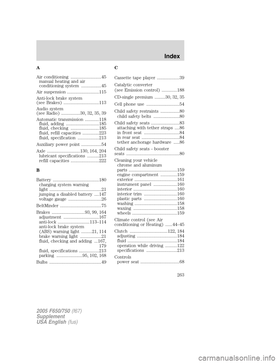
A
Air conditioning ..........................45
manual heating and air
conditioning system .................45
Air suspension ...........................115
Anti-lock brake system
(see Brakes) ..............................113
Audio system
(see Radio) ................30, 32, 35, 39
Automatic transmission ............118
fluid, adding ............................185
fluid, checking ........................185
fluid, refill capacities ..............223
fluid, specification ..................213
Auxiliary power point .................54
Axle ............................130, 164, 204
lubricant specifications ..........213
refill capacities ........................222
B
Battery .......................................180
charging system warning
light ............................................21
jumping a disabled battery ....147
voltage gauge ............................26
BeltMinder ...................................75
Brakes ............................93, 99, 164
adjustment ..............................167
anti-lock ...........................113–114
anti-lock brake system
(ABS) warning light .........21, 114
brake warning light ..................21
fluid, checking and adding ...167,
179
fluid, specifications .................213
parking ......................95, 102, 168
Bulbs ............................................49C
Cassette tape player ...................39
Catalytic converter
(see Emission control) .............188
CD-single premium .........30, 32, 35
Cell phone use ............................54
Child safety restraints ................80
child safety belts ......................80
Child safety seats ........................83
attaching with tether straps ....86
in front seat ..............................84
in rear seat ................................84
tether anchorage hardware .....86
Child safety seats - booster
seats .............................................80
Cleaning your vehicle
chrome and aluminum
parts .........................................159
engine compartment ..............159
exterior ....................................161
instrument panel ....................160
interior .....................................160
interior trim ............................160
plastic parts ............................160
washing ....................................158
waxing .....................................158
wheels ......................................159
Climate control (see Air
conditioning or Heating) ......44–45
Clutch ................................122, 184
adjusting ..................................184
fluid ..........................................184
operation while driving ..........122
specifications ..........................213
Controls
power seat .................................68
2005 F650/750(f67)
Supplement
USA English(fus)
Index
263