ECU FORD F650 2006 11.G User Guide
[x] Cancel search | Manufacturer: FORD, Model Year: 2006, Model line: F650, Model: FORD F650 2006 11.GPages: 272, PDF Size: 1.86 MB
Page 89 of 272
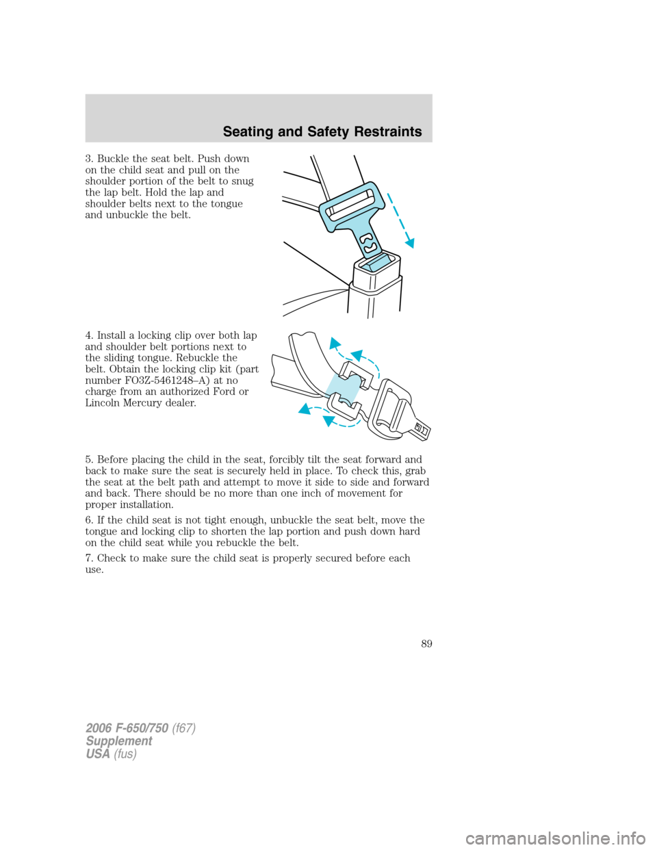
3. Buckle the seat belt. Push down
on the child seat and pull on the
shoulder portion of the belt to snug
the lap belt. Hold the lap and
shoulder belts next to the tongue
and unbuckle the belt.
4. Install a locking clip over both lap
and shoulder belt portions next to
the sliding tongue. Rebuckle the
belt. Obtain the locking clip kit (part
number FO3Z-5461248–A) at no
charge from an authorized Ford or
Lincoln Mercury dealer.
5. Before placing the child in the seat, forcibly tilt the seat forward and
back to make sure the seat is securely held in place. To check this, grab
the seat at the belt path and attempt to move it side to side and forward
and back. There should be no more than one inch of movement for
proper installation.
6. If the child seat is not tight enough, unbuckle the seat belt, move the
tongue and locking clip to shorten the lap portion and push down hard
on the child seat while you rebuckle the belt.
7. Check to make sure the child seat is properly secured before each
use.
2006 F-650/750(f67)
Supplement
USA(fus)
Seating and Safety Restraints
89
Page 90 of 272
Attaching safety seats with tether straps
Most forward-facing child safety seats include a tether strap which goes
over the back of the seat and hooks to an anchoring point. The
F-650/750 vehicles are not equipped with an anchoring point. Tether
straps are available as an accessory for many older safety seats. Contact
the manufacturer of your child safety seat for information about ordering
a tether strap.
Tether anchorage hardware
A tethered seat can be installed in the front seat. Put the tether strap
over the seatback and attach it to an anchor bracket.
An anchor bracket can be installed to the inside of the back panel of
your vehicle.
The anchor bracket must be installed using the instructions provided
with the tether anchorage hardware kit.
Tether anchorage hardware kits (part number 613D74) including
instructions, may be obtained at no charge from any Ford or Lincoln
Mercury dealer.
If you have a SuperCab or Crew Cab, Ford recommends you attach
tether safety seats in the rear seating position (if possible) with the
tether strap attached to the tether anchorage bracket as shown in the
instructions provided with the tether anchor kit.
Tighten the anchor according to specifications. Otherwise, the
safety seat may not be properly secured and the child may be
injured in a sudden stop or collision.
2006 F-650/750(f67)
Supplement
USA(fus)
Seating and Safety Restraints
90
Page 109 of 272
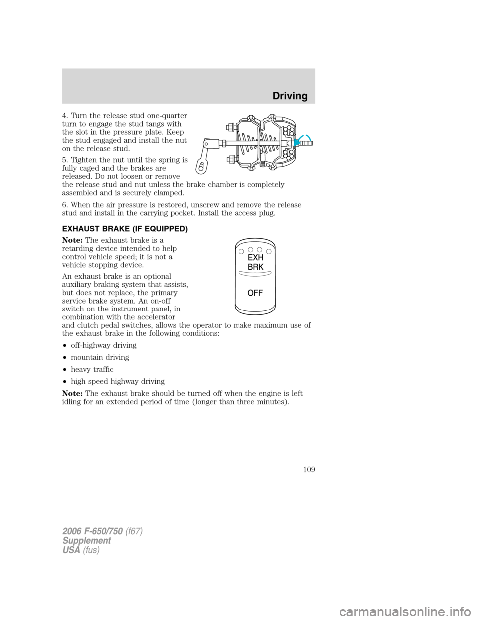
4. Turn the release stud one-quarter
turn to engage the stud tangs with
the slot in the pressure plate. Keep
the stud engaged and install the nut
on the release stud.
5. Tighten the nut until the spring is
fully caged and the brakes are
released. Do not loosen or remove
the release stud and nut unless the brake chamber is completely
assembled and is securely clamped.
6. When the air pressure is restored, unscrew and remove the release
stud and install in the carrying pocket. Install the access plug.
EXHAUST BRAKE (IF EQUIPPED)
Note:The exhaust brake is a
retarding device intended to help
control vehicle speed; it is not a
vehicle stopping device.
An exhaust brake is an optional
auxiliary braking system that assists,
but does not replace, the primary
service brake system. An on-off
switch on the instrument panel, in
combination with the accelerator
and clutch pedal switches, allows the operator to make maximum use of
the exhaust brake in the following conditions:
•off-highway driving
•mountain driving
•heavy traffic
•high speed highway driving
Note:The exhaust brake should be turned off when the engine is left
idling for an extended period of time (longer than three minutes).
2006 F-650/750(f67)
Supplement
USA(fus)
Driving
109
Page 141 of 272
Before hook-up, make sure:
•The fifth wheel jaws are fully opened.
•The fifth wheel is fully tilted back to prevent body damage when the
tractor is backed under a trailer.
•The trailer wheels are blocked and the trailer spring brakes are
adjusted and applied. Never chase a trailer.
•The brake hoses and light cords are clear of the fifth wheel.
Hook-up
1. Back the tractor squarely under the trailer, engaging the fifth wheel
jaws on the kingpin. Always back-up slowly, making sure the trailer is
neither too high nor too low. Avoid backing under the trailer from an
angle.
2. Connect the service and emergency brake hoses and trailer light
connector. Refer toTractor-trailer connectionin this chapter, adhering
to the warning and using the three-point stance while connecting and
disconnecting the trailer.
3. Inspect the jaws of the fifth wheel to be sure they have fully closed on
the trailer kingpin and the trailer plate is resting securely on the fifth
wheel.
4. Be sure the coupler release lever is in the locked position.
5. Charge the trailer brake system. Set the trailer brakes, either with the
hand valve or tractor protection valve. Pull against the trailer for an
additional check of proper hook-up. Do not pull hard enough to damage
or strain the equipment.
6. Set the tractor parking brakes and fully raise the trailer landing gear.
Refer toBrakesin this chapter for proper operation of the parking brake
and trailer brakes.
7. Check the operation of all trailer lights and correct any lights that may
be faulty.
2006 F-650/750(f67)
Supplement
USA(fus)
Driving
141
Page 155 of 272
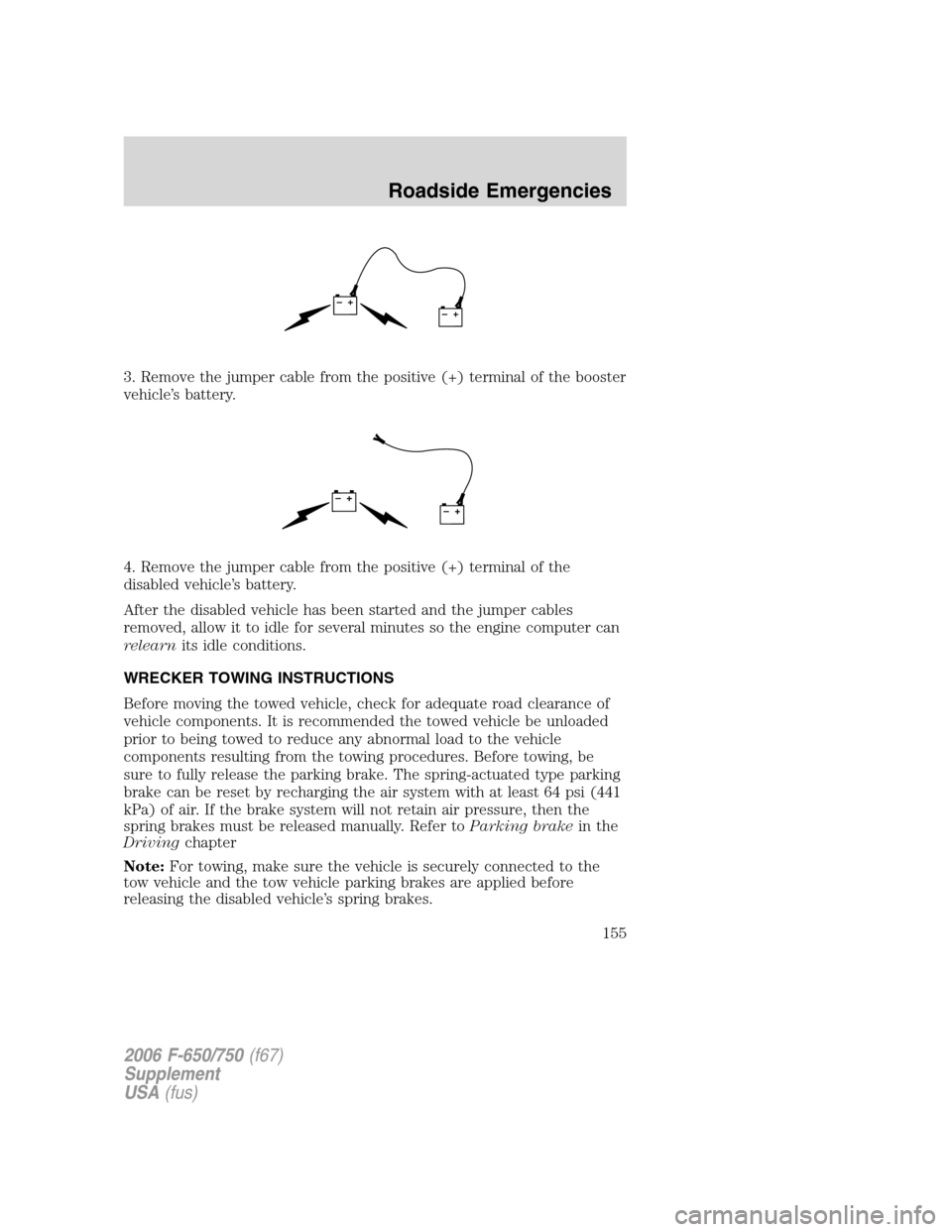
3. Remove the jumper cable from the positive (+) terminal of the booster
vehicle’s battery.
4. Remove the jumper cable from the positive (+) terminal of the
disabled vehicle’s battery.
After the disabled vehicle has been started and the jumper cables
removed, allow it to idle for several minutes so the engine computer can
relearnits idle conditions.
WRECKER TOWING INSTRUCTIONS
Before moving the towed vehicle, check for adequate road clearance of
vehicle components. It is recommended the towed vehicle be unloaded
prior to being towed to reduce any abnormal load to the vehicle
components resulting from the towing procedures. Before towing, be
sure to fully release the parking brake. The spring-actuated type parking
brake can be reset by recharging the air system with at least 64 psi (441
kPa) of air. If the brake system will not retain air pressure, then the
spring brakes must be released manually. Refer toParking brakein the
Drivingchapter
Note:For towing, make sure the vehicle is securely connected to the
tow vehicle and the tow vehicle parking brakes are applied before
releasing the disabled vehicle’s spring brakes.
+–+–
+–+–
2006 F-650/750(f67)
Supplement
USA(fus)
Roadside Emergencies
155
Page 156 of 272
To reduce the risk of personal injury or property damage when
manually releasing the spring brakes, be sure to block the wheels
so the vehicle cannot move once the brakes are released.
Towing the vehicle with the front wheels suspended
When it is necessary to tow a vehicle with the front wheels suspended,
extra precautions must be taken to avoid transmission or differential
damage. Proceed as follows:
•Remove the axle shafts from the axle assembly to prevent the wheels
from driving the differential and the transmission.
•The wheel hub ends must be covered to prevent loss of axle lubricant
and entrance of other contaminants. If the axle shafts are not
removed, removal of the propeller shaft is required.
Note:To avoid transmission damage, vehicles should not be towed even
a short distance without suspending rear wheels or removing the axle
shaft or propeller shaft.
Note:In the event the chassis is equipped with a tandem axle and the
vehicle is to be towed from the front, the forward rear axle may be
raised to clear the road surface and secured to the frame by chains or
U-bolts, allowing only the rear rear axle to contact the road surface. Axle
shafts must be removed from the rear rear axle assembly. The wheel hub
ends must be covered to prevent loss of axle lubricant and entrance of
contaminants. Use extreme care in securing the chains or U-bolts to
avoid possible damage to the brake lines, hoses or other components.
Towing vehicles equipped with a driver-controlled differential lock
Note:If the vehicle must be towed to a service facility with the drive
axle wheels on the ground, it is necessary to remove the axle shafts
before the vehicle is towed.
2006 F-650/750(f67)
Supplement
USA(fus)
Roadside Emergencies
156
Page 161 of 272
In the case of 1 or 2 above, the consumer must also notify the
manufacturer of the need for the repair of the nonconformity at the
following address:
Ford Motor Company
16800 Executive Plaza Drive
Mail Drop 3NE-B
Dearborn, MI 48126
GETTING ASSISTANCE OUTSIDE THE U.S AND CANADA
Before exporting your vehicle to a foreign country, contact the
appropriate foreign embassy or consulate. These officials can inform you
of local vehicle registration regulations and where to find unleaded fuel.
If you cannot find unleaded fuel or can only get fuel with an anti-knock
index lower than is recommended for your vehicle, contact a regional
office or owner relations/customer relationship office.
The use of leaded fuel in your vehicle without proper conversion may
damage the effectiveness of your emission control system and may cause
engine knocking or serious engine damage. Ford Motor Company/Ford of
Canada is not responsible for any damage caused by use of improper
fuel. In the United States, using leaded fuel may also result in difficulty
importing your vehicle back into the U.S.
If your vehicle must be serviced while you are traveling or living in
Central or South America, the Caribbean, or the Middle East, contact the
nearest Ford dealership. If the dealership cannot help you, write or call:
FORD MOTOR COMPANY
WORLDWIDE DIRECT MARKET OPERATIONS
1555 Fairlane Drive
Fairlane Business Park #3
Allen Park, Michigan 48101
U.S.A.
Telephone: (313) 594-4857
FAX: (313) 390-0804
If you are in another foreign country, contact the nearest Ford
dealership. If the dealership employees cannot help you, they can direct
you to the nearest Ford affiliate office.
If you buy your vehicle in North America and then relocate outside of
the U.S. or Canada, register your vehicle identification number (VIN) and
new address with Ford Motor Company Worldwide Direct Market
Operations.
2006 F-650/750(f67)
Supplement
USA(fus)
Customer Assistance
161
Page 170 of 272
Check to make sure that the axle mounting U-bolt nuts, attaching or
mounting bolts and nuts are securely tightened. Regularly check front
axle for damage, binding, worn parts and adequate lubrication.
At regular intervals, or during other scheduled maintenance, (tire
rotation/service, wheel bearing service, alignment, etc.) the kingpins
should be checked for excessive wear. Refer to the service manual for
proper procedures.
Toe-in setting - general inspection
Inspecting steer axle tires in the first 3,000–10,000 service miles
(4,800–16,000 service km) will generally show if tires are wearing
normally.
Rapid outside shoulder wear on both tires indicates too much toe-in.
Rapid inside shoulder wear on both tires indicates too much toe-out. In
P&D-type service, left-to-right steer tire tread life differentials up to 40%
can be observed depending on routes and other variables.
Follow the tire manufacturer’s recommended cold inflation pressure for
the tire size, load range (ply rating) and steer axle loading typical for
their operation (each steer axle tire will equal
1�2steer axle loading).
Special applications may warrant a setting based on past experience with
the type of tire operating loads and conditions. Radial tires are more
sensitive to toe-in setting than bias ply tires. While not insensitive to
vehicle alignment, fine tuning school bus alignment to line-haul truck
standards will not drastically improve tire tread life.
It is essential that correct toe-in and tire pressure be maintained for
optimum tire wear.
Rear axle - general inspection
Check to make sure that the axle mounting U-bolts, attaching or
mounting bolts and nuts are securely tightened. Refer toU-bolt nut
torquein this chapter. Regularly check the rear axle for damaged,
binding or worn parts.
NoSpin Detroit Locker positive locking differential
Vehicles equipped with this type differential have the operator’s manual
supplied with the vehicle. Refer to this manual for maintenance checks.
Brake system - general inspection
Your vehicle is equipped with non-asbestos brake linings. However,
exposure to excessive amounts of brake material (whether asbestos or
2006 F-650/750(f67)
Supplement
USA(fus)
Maintenance and Specifications
170
Page 190 of 272
2. Open the hood.
3. Clean the top of the power steering fluid reservoir.
4. Remove the dipstick from the reservoir and wipe the dipstick clean.
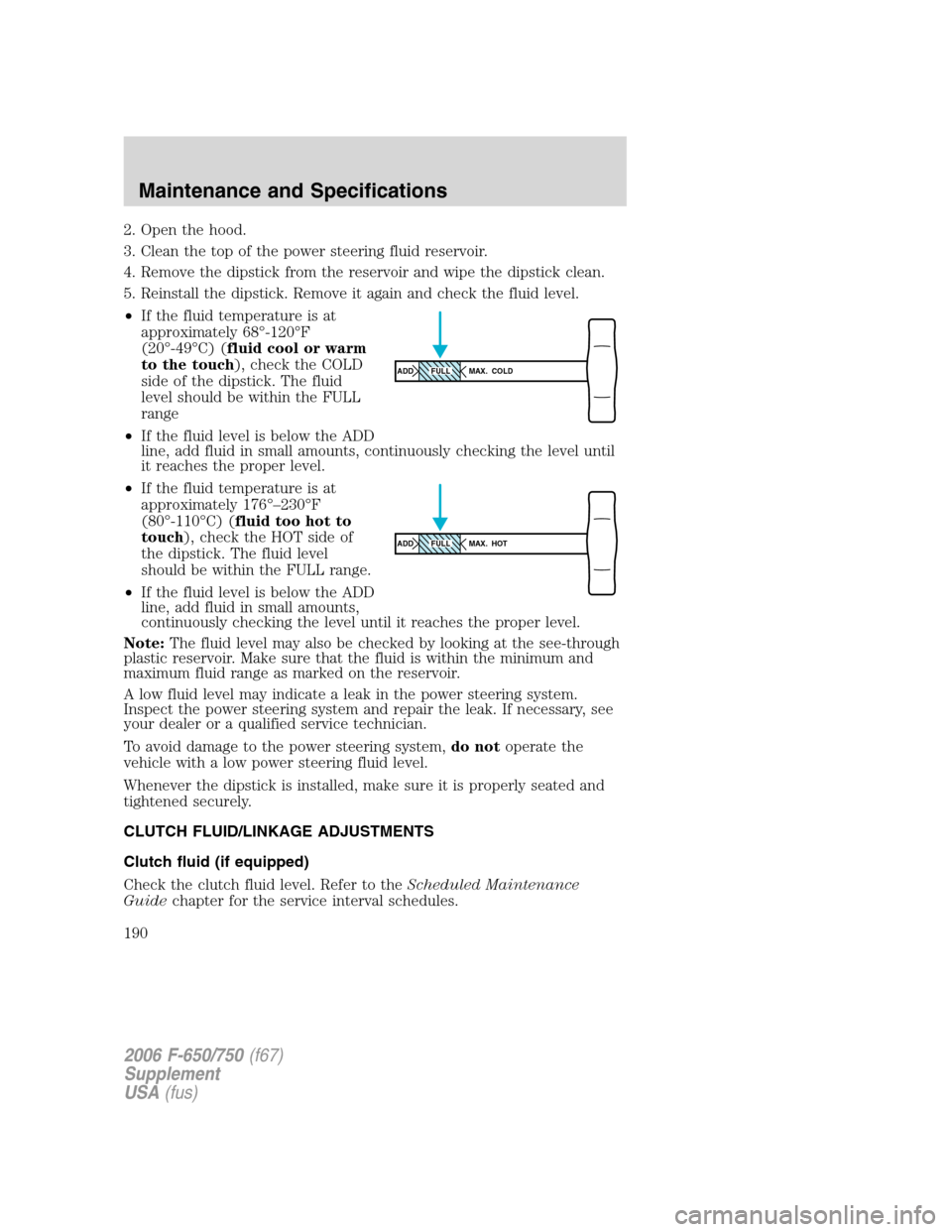
5. Reinstall the dipstick. Remove it again and check the fluid level.
•If the fluid temperature is at
approximately 68°-120°F
(20°-49°C) (fluid cool or warm
to the touch), check the COLD
side of the dipstick. The fluid
level should be within the FULL
range
•If the fluid level is below the ADD
line, add fluid in small amounts, continuously checking the level until
it reaches the proper level.
•If the fluid temperature is at
approximately 176°–230°F
(80°-110°C) (fluid too hot to
touch), check the HOT side of
the dipstick. The fluid level
should be within the FULL range.
•If the fluid level is below the ADD
line, add fluid in small amounts,
continuously checking the level until it reaches the proper level.
Note:The fluid level may also be checked by looking at the see-through
plastic reservoir. Make sure that the fluid is within the minimum and
maximum fluid range as marked on the reservoir.
A low fluid level may indicate a leak in the power steering system.
Inspect the power steering system and repair the leak. If necessary, see
your dealer or a qualified service technician.
To avoid damage to the power steering system,do notoperate the
vehicle with a low power steering fluid level.
Whenever the dipstick is installed, make sure it is properly seated and
tightened securely.
CLUTCH FLUID/LINKAGE ADJUSTMENTS
Clutch fluid (if equipped)
Check the clutch fluid level. Refer to theScheduled Maintenance
Guidechapter for the service interval schedules.
ADD MAX. COLDFULL
ADD MAX. HOTFULL
2006 F-650/750(f67)
Supplement
USA(fus)
Maintenance and Specifications
190
Page 193 of 272
Use of a non-approved automatic transmission fluid may cause
internal transmission component damage.
Manual transmission fluid
Refer to theScheduled Maintenance Guidechapter for transmission
fluid level checks and fluid change intervals.
Your manual transmission may be filled with an optional synthetic fluid
which allows the use of extended service intervals. A tag on the filler
plug will identify the use of the synthetic fluid.
Use only fluid that meets manufacturer specifications (refer to
Lubricant specificationsin this chapter.
Use of a non-approved transmission fluid may cause internal
transmission component damage.
Check your transmission fluid level using the following procedure:
1. Park the vehicle on level ground.
2. Set the parking brake and shift into 1 (First) and turn the engine off.
3. Clean any dirt from around the filler plug.
4. Remove the filler plug and inspect the fluid level.
5. The fluid level should be up to the bottom of the filler plug opening.
6. If necessary, add enough fluid through the filler plug opening so that
the fluid level is at the bottom of the opening.
7. Clean and install the filler plug securely.
Drain and refill your transmission fluid using the following procedure:
1. Drain the transmission while the fluid is warm.
2. Park the vehicle on level ground.
3. Set the parking brake and shift into 1 (First) and turn the engine off.
4. Clean any dirt from around the filler and drain plugs.
5. Remove the filler and drain plugs and drain the fluid into a suitable
container. Dispose all used automotive fluids in a responsible manner
following your local authorized standards.
6. Clean and install the drain plug securely.
7. Add enough fluid through the filler plug opening so that the fluid level
is up to the bottom of the opening.
8. Clean and install the filler plug securely.
2006 F-650/750(f67)
Supplement
USA(fus)
Maintenance and Specifications
193