lug nut FORD F650 2006 11.G Owners Manual
[x] Cancel search | Manufacturer: FORD, Model Year: 2006, Model line: F650, Model: FORD F650 2006 11.GPages: 272, PDF Size: 1.86 MB
Page 18 of 272
Front wheels
Rims:Check for damaged or bent rims. Rims should
not have welding repairs and no rust trails that
indicate it is loose on the wheel.
Lug nuts:Make sure all lug nuts are present and not
loose (look for rust trails around the lug nuts).
There should be no cracks radiating from the
lug bolt holes or distortion of the bolt holes.
Hub oil seal:Check wheel hub oil seal for leaks, and if sight
glass if present, check to see that the oil level
is adequate.
Oil-lubricated front
wheel bearing:If the hubcap has a transparent window, check
for proper lubrication level. If the hubcap does
not have a transparent window, remove the
rubber fill-plug and check for proper level.
If a wheel must be changed, obtain expert tire service help.
Mounting and un-mounting of tires should only be performed by
a qualified technician using necessary safety procedures and
equipment, otherwise the result could be property damage, personal
injury or death.
Driver/Fuel area
Fuel tank:Make sure the fuel tank and caps are secure.
Make sure there is no damage to the tank.
Leaks:Check for any leaks from the fuel tanks.
2006 F-650/750(f67)
Supplement
USA(fus)
Vehicle Inspection Guide
18
Page 21 of 272
Rear springs
Torsion, shocks:Make sure torsion arm is not cracked, broken
or missing. Check the shock absorber for
cracks or leaks; there should be no missing or
broken mounting bolts or worn bushings.
Rear brakes
Hoses:Checked for cracked, worn or frayed hoses.
Make sure all couplings are secured.
Chambers:Make sure brake chambers are not cracked or
dented and that they are securely mounted.
Slack adjuster:Check for broken, loose or missing parts; the
angle between the push rod and adjuster arm
should be approximately 90° when the brakes
are applied. When pulled by hand, the push
rod should not move more than approximately
one inch (2.5 cm).
Drum:Make sure there are no cracks, dents or holes
and no loose or missing bolts. Make sure brake
linings are not worn or dangerously thin or
contaminated by lubricant.
Rear wheels
Spacers:Make sure dual wheels are evenly separated
and that tires are not touching one another.
Rims:Check for damaged or bent rims. Rims should
not have welding repairs and no rust trails that
indicate it is loose on the wheel.
Lug nuts:Make sure all lug nuts are present and not
loose (look for rust trails around the lug nuts).
There should be no cracks radiating from the
lug bolt holes or distortion of the bolt holes.
2006 F-650/750(f67)
Supplement
USA(fus)
Vehicle Inspection Guide
21
Page 93 of 272
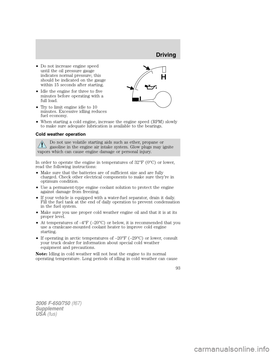
•Do not increase engine speed
until the oil pressure gauge
indicates normal pressure; this
should be indicated on the gauge
within 15 seconds after starting.
•Idle the engine for three to five
minutes before operating with a
full load.
•Try to limit engine idle to 10
minutes. Excessive idling reduces
fuel economy.
•When starting a cold engine, increase the engine speed (RPM) slowly
to make sure adequate lubrication is available to the bearings.
Cold weather operation
Do not use volatile starting aids such as ether, propane or
gasoline in the engine air intake system. Glow plugs may ignite
vapors which can cause engine damage or personal injury.
In order to operate the engine in temperatures of 32°F (0°C) or lower,
read the following instructions:
•Make sure that the batteries are of sufficient size and are fully
charged. Check other electrical components to make sure they’re in
optimum condition.
•Use a permanent-type engine coolant solution to protect the engine
against damage from freezing.
•If your vehicle is equipped with a water-fuel separator, drain it daily.
Fill the fuel tank at the end of daily operation to prevent condensation
in the fuel system.
•Make sure you use proper cold weather engine oil and that it is at its
proper level.
•At temperatures of –4°F (–20°C) or below, it is recommended that you
use a crankcase-mounted coolant heater to improve cold engine
starting.
•If operating in arctic temperatures of –20°F (–29°C) or lower, consult
your truck dealer for information about special cold weather
equipment and precautions.
Note:Idling in cold weather will not heat the engine to its normal
operating temperature. Long periods of idling in cold weather can cause
L
H
2006 F-650/750(f67)
Supplement
USA(fus)
Driving
93
Page 94 of 272
a buildup of heavy deposits of carbon and rust on valve stems causing
them to stick which, in turn, can cause valvetrain damage.
The following cold weather idling guidelines must be followed:
•Avoid idling the engine for more than 10 minutes at a time.
•Use a minimum of 45 Cetane Diesel fuel or use Cetane Index
improvers from a reputable manufacturer.
•Maintain a minimum idle of 1250 RPM by using the hand throttle.
Always make sure that the parking brake is applied and the
transmission is in neutral before applying the hand throttle.
•Maintain the engine cooling system properly.
•Do not shut the engine down after an extensive idling period (10
minutes or more). Drive the vehicle under load for several miles at
normal operating temperatures to burn off any accumulated carbon
and varnish.
•Consider using an engine block heater, approved winter fronts and/or
radiator shutters where conditions warrant.
Winter fronts
The use of winter fronts, or other air-restrictive devices mounted in front
of the radiator on vehicles with chassis-mounted charge air coolers, are
not recommended unless extremely cold weather conditions exist. Air
flow restriction can cause high exhaust temperatures, power loss,
excessive fan usage and a reduction in fuel economy. If you must use a
winter front, the device should have a permanent opening of at least 120
sq in. (774 sq. cm) directly in line with the fan hub.
Hot weather operation
•Keep the engine cooling system filled with a clean, permanent coolant
solution to protect against damage from overheating.
•Fill the fuel tank at the end of daily operation to prevent condensation
in the fuel system.
•Keep external surfaces of the engine, radiator, charge air cooler, A/C
condenser and accessories clean to avoid dirt build-up.
Above normal coolant temperatures could be experienced while driving
in a transmission gear ratio which lugs the engine. To correct this
problem, engine speed should be increased by downshifting in to the
next lower gear to increase engine RPM.
Starting a turbocharged engine with the vehicle on a steep grade
When starting a diesel engine when the loaded vehicle is on a grade, the
engine RPM will start to fall slightly when the clutch is engaged; do not
2006 F-650/750(f67)
Supplement
USA(fus)
Driving
94
Page 108 of 272
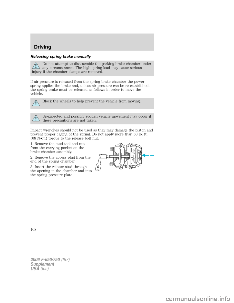
Releasing spring brake manually
Do not attempt to disassemble the parking brake chamber under
any circumstances. The high spring load may cause serious
injury if the chamber clamps are removed.
If air pressure is released from the spring brake chamber the power
spring applies the brake and, unless air pressure can be re-established,
the spring brake must be released as follows in order to move the
vehicle.
Block the wheels to help prevent the vehicle from moving.
Unexpected and possibly sudden vehicle movement may occur if
these precautions are not taken.
Impact wrenches should not be used as they may damage the piston and
prevent proper caging of the spring. Do not apply more than 50 lb. ft.
(68 N•m) torque to the release bolt nut.
1. Remove the stud tool and nut
from the carrying pocket on the
brake chamber assembly.
2. Remove the access plug from the
end of the spring chamber.
3. Insert the release stud through
the opening in the chamber and into
the spring pressure plate.
2006 F-650/750(f67)
Supplement
USA(fus)
Driving
108
Page 109 of 272
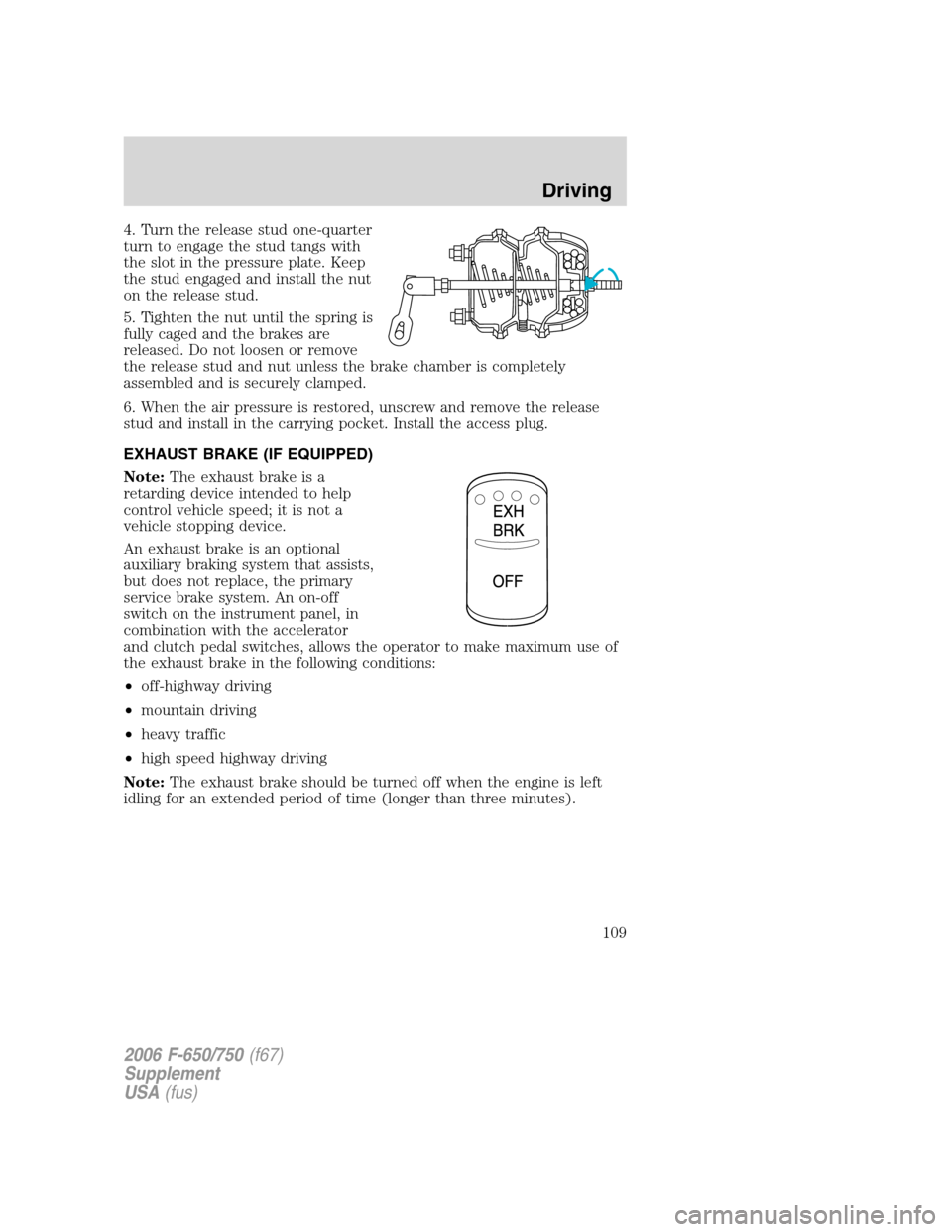
4. Turn the release stud one-quarter
turn to engage the stud tangs with
the slot in the pressure plate. Keep
the stud engaged and install the nut
on the release stud.
5. Tighten the nut until the spring is
fully caged and the brakes are
released. Do not loosen or remove
the release stud and nut unless the brake chamber is completely
assembled and is securely clamped.
6. When the air pressure is restored, unscrew and remove the release
stud and install in the carrying pocket. Install the access plug.
EXHAUST BRAKE (IF EQUIPPED)
Note:The exhaust brake is a
retarding device intended to help
control vehicle speed; it is not a
vehicle stopping device.
An exhaust brake is an optional
auxiliary braking system that assists,
but does not replace, the primary
service brake system. An on-off
switch on the instrument panel, in
combination with the accelerator
and clutch pedal switches, allows the operator to make maximum use of
the exhaust brake in the following conditions:
•off-highway driving
•mountain driving
•heavy traffic
•high speed highway driving
Note:The exhaust brake should be turned off when the engine is left
idling for an extended period of time (longer than three minutes).
2006 F-650/750(f67)
Supplement
USA(fus)
Driving
109
Page 140 of 272
Trailer towing tips
•Practice turning, stopping and backing up before starting on a trip to
get the feel of the vehicle trailer combination. When turning, make
wider turns so the trailer wheels will clear curbs and other obstacles.
•Allow more distance for stopping with a trailer attached.
•If you are driving down a long or steep hill, shift to a lower gear. Do
not apply the brakes continuously, as they may overheat and become
less effective.
•The trailer tongue weight should be 10–15% of the loaded trailer
weight.
•If you will be towing a trailer frequently in hot weather, hilly
conditions, at GCW, or any combination of these factors, consider
refilling your rear axle with synthetic gear lube if not already so
equipped. Refer toLubricant Specificationsin theMaintenance
and Specificationschapter for the lubricant specification. Remember
that regardless of the rear axle lube used, do not tow a trailer for the
first 500 miles (800 km) of a new vehicle, and that the first 500 miles
(800 km) of towing be done at no faster than 70 mph (112 km/h) with
no full throttle starts.
•After you have traveled 50 miles (80 km), thoroughly check your
hitch, electrical connections and trailer wheel lug nuts.
•To aid in engine/transmission cooling and A/C efficiency during hot
weather while stopped in traffic, place the gearshift lever in P (Park)
(if available on your automatic transmission) or N (Neutral) (manual
transmissions and automatic transmissions withoutaP[Park]
position).
•Vehicles with trailers should not be parked on a grade. If you must
park on a grade, place wheel chocks under the trailer’s wheels.
FIFTH WHEEL OPERATION
Failure to follow the fifth wheel manufacturer’s instructions for
hooking and unhooking as well as sliding the fifth wheel could
result in an accident, personal injury or death.
When the tractor and trailer are parked unattended, the trailer
brake hand control should never be used to apply the brake,
since air may leak from the system, allowing vehicle movement,
resulting in possible property damage, personal injury or death.
2006 F-650/750(f67)
Supplement
USA(fus)
Driving
140
Page 207 of 272
6. Re-torque the nuts to 425 ft. lb (576 N•m), using a diagonal pattern.
(For vehicles equipped with 14ACC, 14 ADN and 14ADP axles.)
7. Use the same diagonal pattern with each U-bolt nut re-torque.
Spring U-bolt checks
Check U-bolt nuts and re-torque every 36,000 miles (58,000 km) after
initial 1,000 miles (1,600 km) re-torque. The U-bolt and nut threads and
seats should be cleaned and lubricated to ensure peak condition when
re-torqued.
PROPELLER SHAFT
At the regular lubrication interval, check the universal joints for any
evidence of wear or looseness. Should propeller shaft vibrations occur,
stop the vehicle immediately to avoid possible hazardous consequences
or damage to other components.
REAR AXLE LUBRICANT
Refer to theScheduled Maintenance Guidechapter for rear axle
lubricant level checks and lubricant change intervals.
Your rear axle may be filled with an optional synthetic lubricant which
allows the use of extended service intervals. A tag on the filler plug will
identify the use of the synthetic lubricant.
Use only a lubricant that meets manufacturer specifications (refer to
Lubricant specificationsin this chapter).
Use of a non-approved rear axle lubricant may cause internal axle
component damage.
Checking the rear axle lubricant level
1. Park the vehicle on level ground.
2. Set the parking brake and shift into N (Neutral) (automatic
transmission) or 1 (First) (manual transmission) and turn the engine off.
3. Clean any dirt from around the rear axle filler plug.
4. Remove the filler plug and inspect the lubricant level.
5. The lubricant level should be up to the bottom of the filler plug
opening.
6. If necessary, add enough lubricant through the filler plug opening so
that the lubricant level is at the bottom of the opening.
7. Clean and install the filler plug securely.
2006 F-650/750(f67)
Supplement
USA(fus)
Maintenance and Specifications
207
Page 209 of 272
Normal maintenance
Over a period of time, if not routinely cleaned, a slight film of oil can
collect dirt around the rubber fill plug and face, which could appear to
be a leak. Routine cleaning ensures that the lube level can be easily
observed through the clear window as intended. In situations where the
window is clean on the outside but discolored on the inside, the lube
level may be checked by inserting a finger through the rubber check
vent hole.
The specified lube level for a clear window type hubcaps is from the
minimum line to + 5/16 inch above the minimum line.
If the lube level should suddenly drop dramatically below the minimum
level, see the Service Manual for diagnostic procedure.
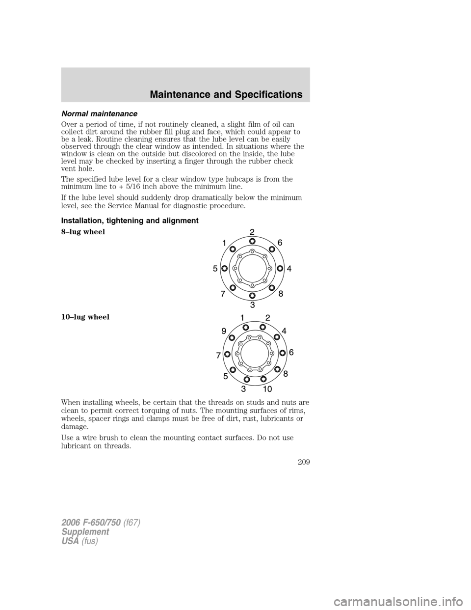
Installation, tightening and alignment
8–lug wheel
10–lug wheel
When installing wheels, be certain that the threads on studs and nuts are
clean to permit correct torquing of nuts. The mounting surfaces of rims,
wheels, spacer rings and clamps must be free of dirt, rust, lubricants or
damage.
Use a wire brush to clean the mounting contact surfaces. Do not use
lubricant on threads.
2006 F-650/750(f67)
Supplement
USA(fus)
Maintenance and Specifications
209
Page 210 of 272
After the rim or wheel has been properly tightened, it should be checked
for alignment. Rotate the wheel with a piece of chalk attached to a
steady, firm surface, and placed to just barely clear the outside surface of
the tire bead seat. This procedure will point out the high spot. A high
spot does not necessarily mean that the lug nuts have been unevenly
tightened. This condition or misalignment could be caused by a bent
wheel.
Checking the alignment of the wheel/rim installation is more important
on cast spoke rims since the rims can be drawn out of alignment when
improperly tightened. Use the following installation procedures.
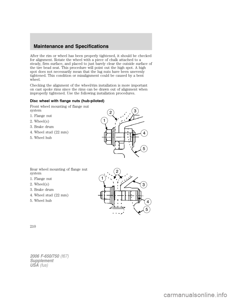
Disc wheel with flange nuts (hub-piloted)
Front wheel mounting of flange nut
system
1. Flange nut
2. Wheel(s)
3. Brake drum
4. Wheel stud (22 mm)
5. Wheel hub
Rear wheel mounting of flange nut
system
1. Flange nut
2. Wheel(s)
3. Brake drum
4. Wheel stud (22 mm)
5. Wheel hub
2006 F-650/750(f67)
Supplement
USA(fus)
Maintenance and Specifications
210