brake FORD F650 2007 11.G Repair Manual
[x] Cancel search | Manufacturer: FORD, Model Year: 2007, Model line: F650, Model: FORD F650 2007 11.GPages: 280, PDF Size: 1.93 MB
Page 137 of 280
Do not connect a trailer’s hydraulic brake system directly to your
vehicle’s brake system. Your vehicle may not have enough
braking power and your chances of having a collision greatly increase.
Trailer lamps
Trailer lamps are required on most towed vehicles. Your vehicle may be
equipped with one of two possible trailer wiring designs. Make sure all
running lights, brake lights, turn signals and hazard lights are working.
See your dealer or trailer rental agency for proper instructions and
equipment for hooking up trailer lamps.
Driving while you tow
When towing a trailer:
• Keep your speed no faster than 70 mph (112 km/h) during the first
500 miles (800 km) of towing a trailer, and don’t make full throttle
starts.
• Turn off the speed control. The speed control may shut off
automatically when you are towing on long, steep grades.
• Consult your local motor vehicle speed regulations for towing a trailer.
• To eliminate excessive transmission shifting, use a lower gear. This will
also assist in transmission cooling.
• Anticipate stops and brake gradually.
• Do not exceed the GCWR rating or transmission damage may occur.
Servicing after towing
If you tow a trailer for long distances, your vehicle will require more
frequent service intervals. Refer to your Scheduled Maintenance Guide
for more information.
Trailer towing tips
• Practice turning, stopping and backing up before starting on a trip to
get the feel of the vehicle trailer combination. When turning, make
wider turns so the trailer wheels will clear curbs and other obstacles.
• Allow more distance for stopping with a trailer attached.
• If you are driving down a long or steep hill, shift to a lower gear. Do
not apply the brakes continuously, as they may overheat and become
less effective.
2007 F-650/750 (f67)
Supplement
USA (fus)
Driving
137
Page 138 of 280
•The trailer tongue weight should be 10–15% of the loaded trailer
weight.
• If you will be towing a trailer frequently in hot weather, hilly
conditions, at GCW, or any combination of these factors, consider
refilling your rear axle with synthetic gear lube if not already so
equipped. Refer to Lubricant specifications in theMaintenance and
Specifications chapter for the lubricant specification. Remember that
regardless of the rear axle lube used, do not tow a trailer for the first
500 miles (800 km) of a new vehicle, and that the first 500 miles (800
km) of towing be done at no faster than 70 mph (112 km/h) with no
full throttle starts.
• After you have traveled 50 miles (80 km), thoroughly check your
hitch, electrical connections and trailer wheel lug nuts.
• To aid in engine/transmission cooling and A/C efficiency during hot
weather while stopped in traffic, place the gearshift lever in P (Park)
(if available on your automatic transmission) or N (Neutral) (manual
transmissions and automatic transmissions withou taP[Park]
position).
• Vehicles with trailers should not be parked on a grade. If you must
park on a grade, place wheel chocks under the trailer’s wheels.
FIFTH WHEEL OPERATION
Failure to follow the fifth wheel manufacturer’s instructions for
hooking and unhooking as well as sliding the fifth wheel could
result in an accident, personal injury or death.
When the tractor and trailer are parked unattended, the trailer
brake hand control should never be used to apply the brake,
since air may leak from the system, allowing vehicle movement,
resulting in possible property damage, personal injury or death.
Before hook-up, make sure:
• The fifth wheel jaws are fully opened.
• The fifth wheel is fully tilted back to prevent body damage when the
tractor is backed under a trailer.
• The trailer wheels are blocked and the trailer spring brakes are
adjusted and applied. Never chase a trailer.
• The brake hoses and light cords are clear of the fifth wheel.
2007 F-650/750 (f67)
Supplement
USA (fus)
Driving
138
Page 139 of 280
Hook-up
1.
Back the tractor squarely under the trailer, engaging the fifth wheel jaws
on the kingpin. Always back-up slowly, making sure the trailer is neither too
high nor too low. Avoid backing under the trailer from an angle.
2. Connect the service and emergency brake hoses and trailer light
connector. Refer to Tractor-trailer connection in this chapter, adhering
to the warning and using the three-point stance while connecting and
disconnecting the trailer.
3.
Inspect the jaws of the fifth wheel to be sure they have fully closed on
the trailer kingpin and the trailer plate is resting securely on the fifth wheel.
4. Be sure the coupler release lever is in the locked position.
5. Charge the trailer brake system. Set the trailer brakes, either with the
hand valve or tractor protection valve. Pull against the trailer for an
additional check of proper hook-up. Do not pull hard enough to damage
or strain the equipment.
6. Set the tractor parking brakes and fully raise the trailer landing gear.
Refer to Brakesin this chapter for proper operation of the parking brake
and trailer brakes.
7. Check the operation of all trailer lights and correct any lights that may
be faulty.
Un-hook
1. Try to keep the tractor and trailer in a straight line.
2. Apply the parking brakes.
3. Lower the trailer landing gear, making sure it is on solid, level ground.
The weight of the trailer is to be on the landing gear.
4. Block the trailer wheels.
5. Disconnect the brake hoses and light cords. Be sure hoses and cords
are clear.
6. Pull coupler release lever to disengage the fifth wheel jaws.
7. Release the tractor parking brakes.
8. Pull out from the trailer slowly, allowing the landing gear to take the
load gradually.
2007 F-650/750 (f67)
Supplement
USA (fus)
Driving
139
Page 142 of 280
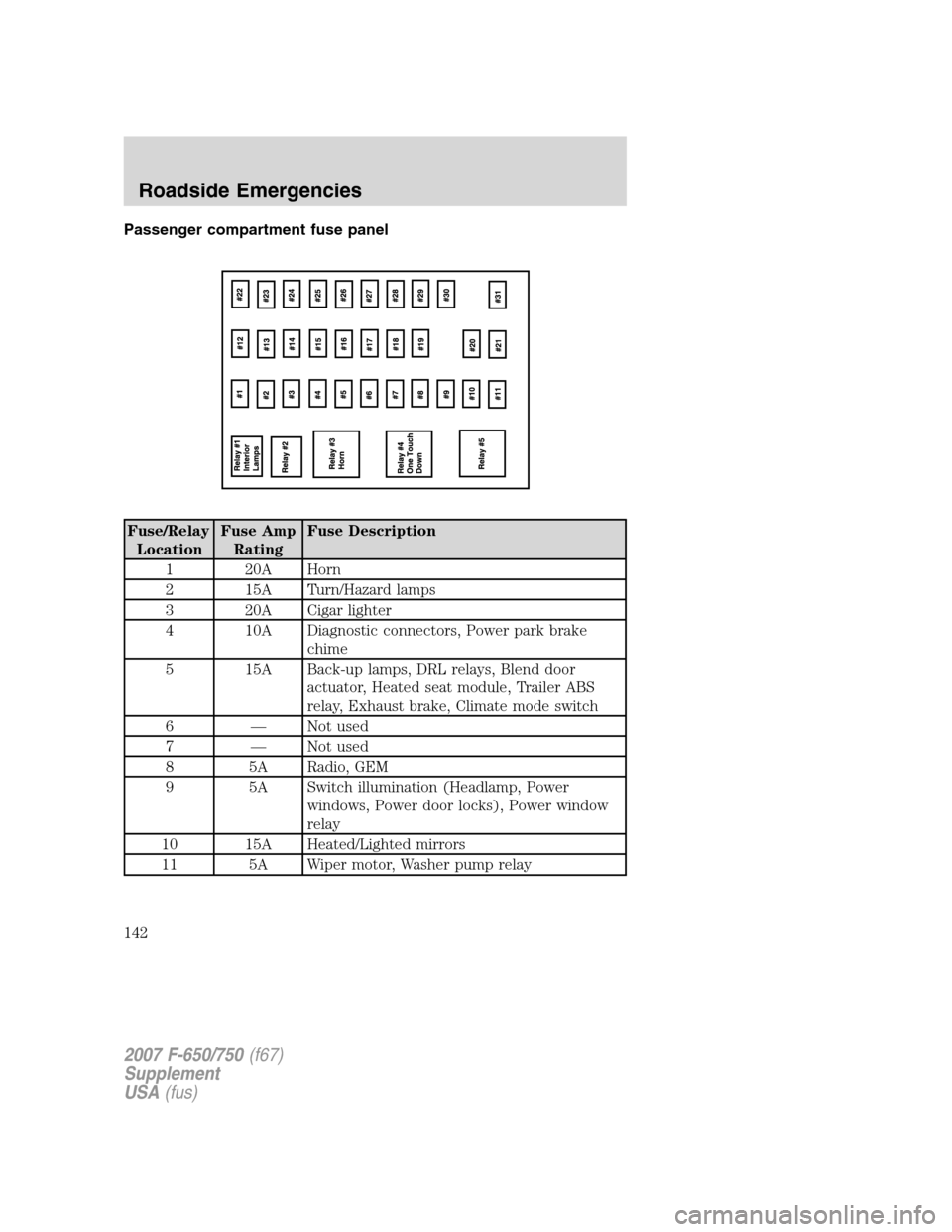
Passenger compartment fuse panel
Fuse/Relay
LocationFuse Amp
RatingFuse Description
1 20A Horn
2 15A Turn/Hazard lamps
3 20A Cigar lighter
4 10A Diagnostic connectors, Power park brake
chime
5 15A Back-up lamps, DRL relays, Blend door
actuator, Heated seat module, Trailer ABS
relay, Exhaust brake, Climate mode switch
6 — Not used
7 — Not used
8 5A Radio, GEM
9 5A Switch illumination (Headlamp, Power
windows, Power door locks), Power window
relay
10 15A Heated/Lighted mirrors
11 5A Wiper motor, Washer pump relay
2007 F-650/750(f67)
Supplement
USA(fus)
Roadside Emergencies
142
Page 143 of 280
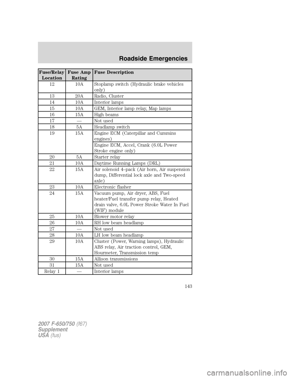
Fuse/Relay
LocationFuse Amp
RatingFuse Description
12 10A Stoplamp switch (Hydraulic brake vehicles
only)
13 20A Radio, Cluster
14 10A Interior lamps
15 10A GEM, Interior lamp relay, Map lamps
16 15A High beams
17 — Not used
18 5A Headlamp switch
19 15A Engine ECM (Caterpillar and Cummins
engines)
Engine ECM, Accel, Crank (6.0L Power
Stroke engine only)
20 5A Starter relay
21 10A Daytime Running Lamps (DRL)
22 15A Air solenoid 4–pack (Air horn, Air suspension
dump, Differential lock axle and Two-speed
axle)
23 10A Electronic flasher
24 15A Vacuum pump, Air dryer, ABS, Fuel
heater/Fuel transfer pump relay, Heated
drain valve, 6.0L Power Stroke Water In Fuel
(WIF) module
25 10A Blower motor relay
26 10A RH low beam headlamp
27 — Not used
28 10A LH low beam headlamp
29 10A Cluster (Power, Warning lamps), Hydraulic
ABS relay, Air traction control, GEM,
Hourmeter, Transmission temp
30 15A Allison transmissions
31 15A Not used
Relay 1 — Interior lamps
2007 F-650/750(f67)
Supplement
USA(fus)
Roadside Emergencies
143
Page 144 of 280
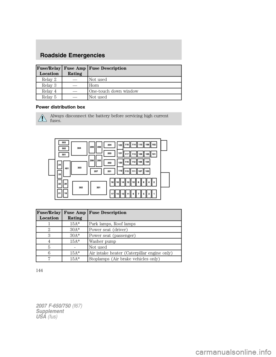
Fuse/RelayLocation Fuse Amp
Rating Fuse Description
Relay 2 — Not used
Relay 3 — Horn
Relay 4 — One-touch down window
Relay 5 — Not used
Power distribution box
Always disconnect the battery before servicing high current
fuses.
Fuse/Relay Location Fuse Amp
Rating Fuse Description
1 15A* Park lamps, Roof lamps
2 30A* Power seat (driver)
3 30A* Power seat (passenger)
4 15A* Washer pump
5 - Not used
6 15A* Air intake heater (Caterpillar engine only)
7 15A* Stoplamps (Air brake vehicles only)
2007 F-650/750 (f67)
Supplement
USA (fus)
Roadside Emergencies
144
Page 145 of 280
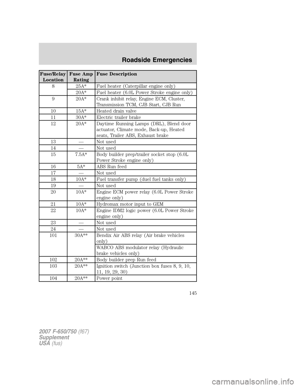
Fuse/Relay
LocationFuse Amp
RatingFuse Description
8 25A* Fuel heater (Caterpillar engine only)
20A* Fuel heater (6.0L Power Stroke engine only)
9 20A* Crank inhibit relay, Engine ECM, Cluster,
Transmission TCM, CJB Start, CJB Run
10 15A* Heated drain valve
11 30A* Electric trailer brake
12 20A* Daytime Running Lamps (DRL), Blend door
actuator, Climate mode, Back-up, Heated
seats, Trailer ABS, Exhaust brake
13 — Not used
14 — Not used
15 7.5A* Body builder prep/trailer socket stop (6.0L
Power Stroke engine only)
16 5A* ABS Run feed
17 — Not used
18 10A* Fuel transfer pump (duel fuel tanks only)
19 — Not used
20 10A* Engine ECM power relay (6.0L Power Stroke
engine only)
21 10A* Hydromax motor input to GEM
22 10A* Engine IDM2 logic power (6.0L Power Stroke
engine only)
23 — Not used
24 — Not used
101 30A** Bendix Air ABS relay (Air brake vehicles
only)
WABCO ABS modulator relay (Hydraulic
brake vehicles only)
102 20A** Body builder prep Run feed
103 20A** Ignition switch (Junction box fuses 8, 9, 10,
11, 19, 29, 30)
104 20A** Power point
2007 F-650/750(f67)
Supplement
USA(fus)
Roadside Emergencies
145
Page 146 of 280
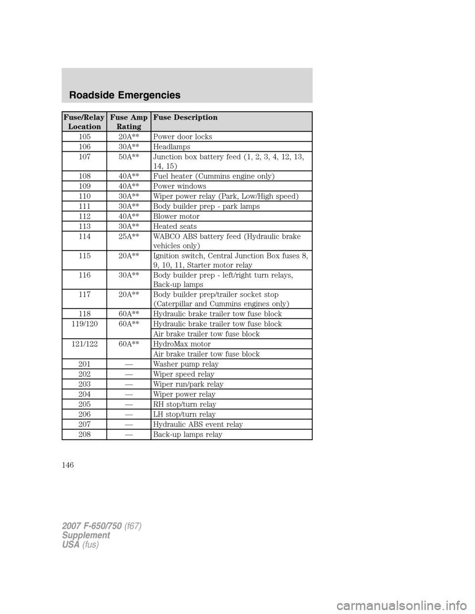
Fuse/Relay
LocationFuse Amp
RatingFuse Description
105 20A** Power door locks
106 30A** Headlamps
107 50A** Junction box battery feed (1, 2, 3, 4, 12, 13,
14, 15)
108 40A** Fuel heater (Cummins engine only)
109 40A** Power windows
110 30A** Wiper power relay (Park, Low/High speed)
111 30A** Body builder prep - park lamps
112 40A** Blower motor
113 30A** Heated seats
114 25A** WABCO ABS battery feed (Hydraulic brake
vehicles only)
115 20A** Ignition switch, Central Junction Box fuses 8,
9, 10, 11, Starter motor relay
116 30A** Body builder prep - left/right turn relays,
Back-up lamps
117 20A** Body builder prep/trailer socket stop
(Caterpillar and Cummins engines only)
118 60A** Hydraulic brake trailer tow fuse block
119/120 60A** Hydraulic brake trailer tow fuse block
Air brake trailer tow fuse block
121/122 60A** HydroMax motor
Air brake trailer tow fuse block
201 — Washer pump relay
202 — Wiper speed relay
203 — Wiper run/park relay
204 — Wiper power relay
205 — RH stop/turn relay
206 — LH stop/turn relay
207 — Hydraulic ABS event relay
208 — Back-up lamps relay
2007 F-650/750(f67)
Supplement
USA(fus)
Roadside Emergencies
146
Page 149 of 280
capability. Attempting to push-start a vehicle with an automatic
transmission may cause transmission damage.
Before connecting a fast-charger, booster battery or installing a new
battery, make sure the ground polarities of the fast-charger, booster
battery or alternator (when installing a battery) are matched to the
ground polarity of the vehicle battery. Improper usage of the
fast-charger, hook-up of booster battery or installation of a new battery
can cause damage to the electrical system or to the alternator. Do not
attempt to polarize the alternator.
Preparing your vehicle
1.Use only a 12–volt supply to start your vehicle.Do not attach the
jumper cables to the glow plug relay as this could severely damage the
glow plugs, injector driver module and PCM.
2. Do not disconnect the battery of the disabled vehicle as this could
damage the vehicle’s electrical system.
3. Park the booster vehicle close to the hood of the disabled vehicle
making sure the two vehiclesdo nottouch. Set the parking brake on
both vehicles and stay clear of the engine cooling fan and other moving
parts.
4. Check all battery terminals and remove any excessive corrosion before
you attach the battery cables. Ensure that vent caps are tight and level.
5. Turn the heater fan on in both vehicles to protect any electrical
surges. Turn all other accessories off.
Connecting the jumper cables
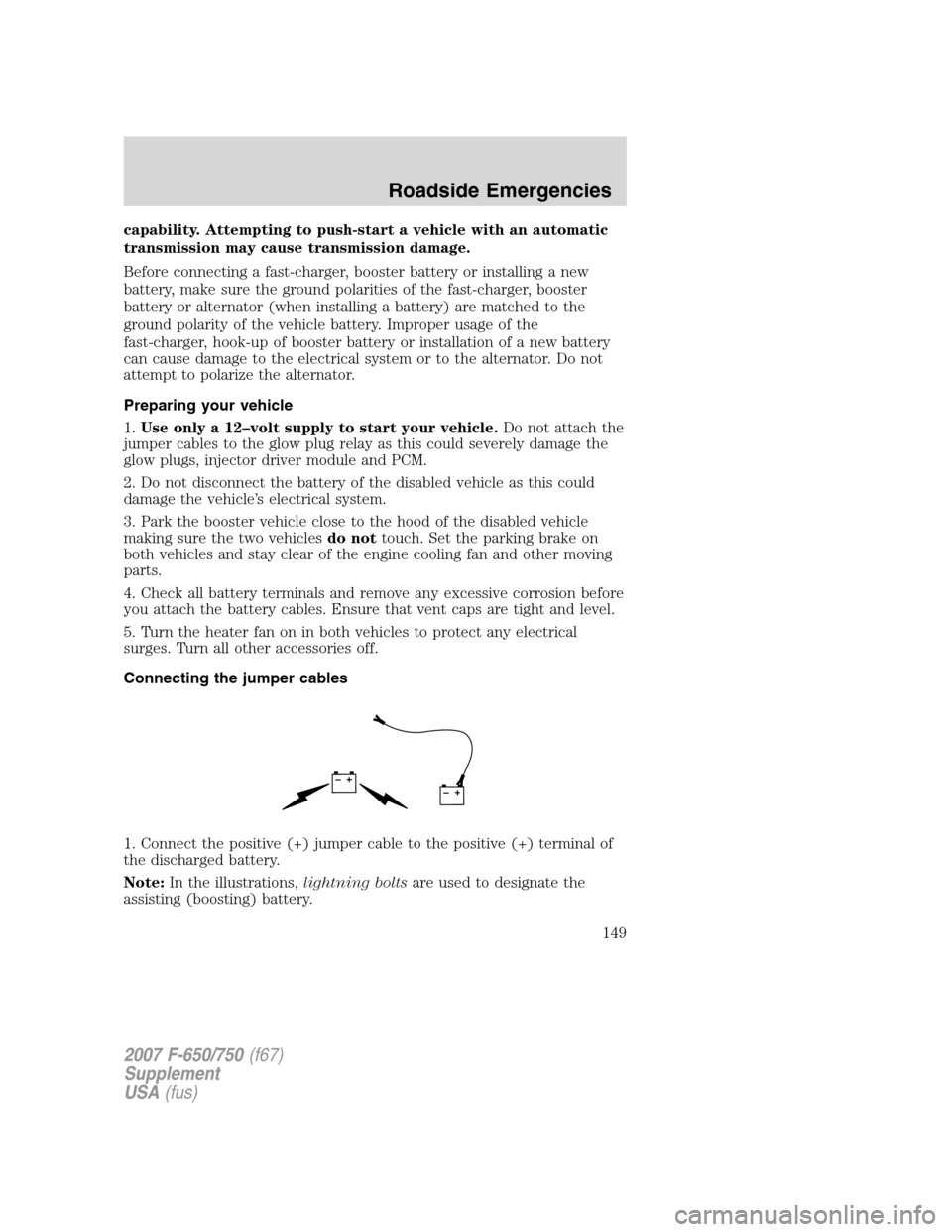
1. Connect the positive (+) jumper cable to the positive (+) terminal of
the discharged battery.
Note:In the illustrations,lightning boltsare used to designate the
assisting (boosting) battery.
+–+–
2007 F-650/750(f67)
Supplement
USA(fus)
Roadside Emergencies
149
Page 152 of 280
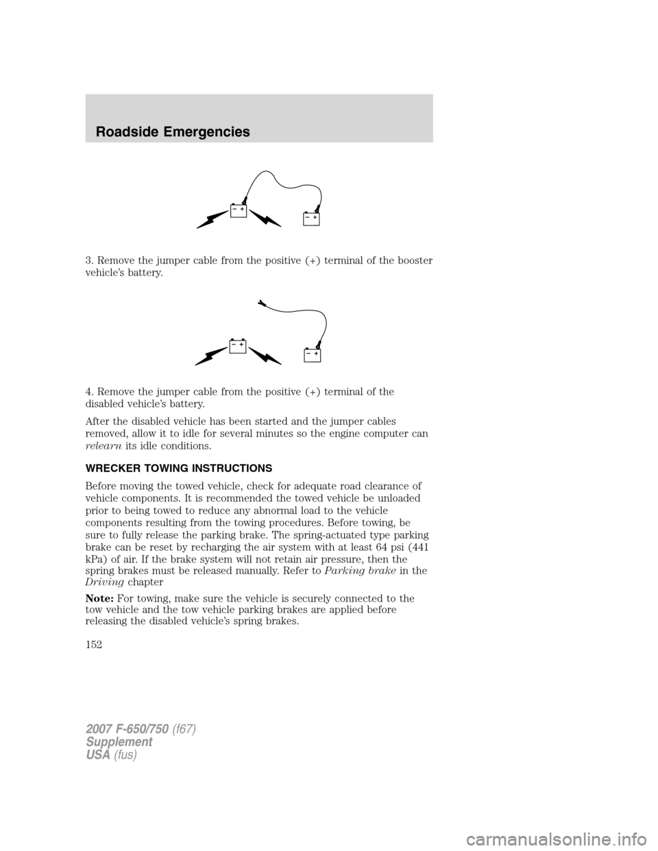
3. Remove the jumper cable from the positive (+) terminal of the booster
vehicle’s battery.
4. Remove the jumper cable from the positive (+) terminal of the
disabled vehicle’s battery.
After the disabled vehicle has been started and the jumper cables
removed, allow it to idle for several minutes so the engine computer can
relearnits idle conditions.
WRECKER TOWING INSTRUCTIONS
Before moving the towed vehicle, check for adequate road clearance of
vehicle components. It is recommended the towed vehicle be unloaded
prior to being towed to reduce any abnormal load to the vehicle
components resulting from the towing procedures. Before towing, be
sure to fully release the parking brake. The spring-actuated type parking
brake can be reset by recharging the air system with at least 64 psi (441
kPa) of air. If the brake system will not retain air pressure, then the
spring brakes must be released manually. Refer toParking brakein the
Drivingchapter
Note:For towing, make sure the vehicle is securely connected to the
tow vehicle and the tow vehicle parking brakes are applied before
releasing the disabled vehicle’s spring brakes.
+–+–
+–+–
2007 F-650/750(f67)
Supplement
USA(fus)
Roadside Emergencies
152