steering FORD F650 2008 11.G User Guide
[x] Cancel search | Manufacturer: FORD, Model Year: 2008, Model line: F650, Model: FORD F650 2008 11.GPages: 273, PDF Size: 1.71 MB
Page 86 of 273
STARTING
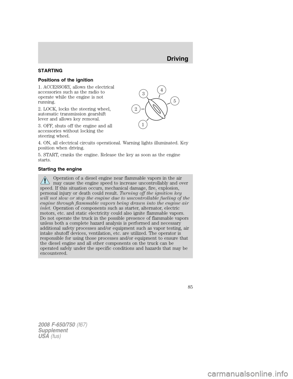
Positions of the ignition
1. ACCESSORY, allows the electrical
accessories such as the radio to
operate while the engine is not
running.
2. LOCK, locks the steering wheel,
automatic transmission gearshift
lever and allows key removal.
3. OFF, shuts off the engine and all
accessories without locking the
steering wheel.
4. ON, all electrical circuits operational. Warning lights illuminated. Key
position when driving.
5. START, cranks the engine. Release the key as soon as the engine
starts.
Starting the engine
Operation of a diesel engine near flammable vapors in the air
may cause the engine speed to increase uncontrollably and over
speed. If this situation occurs, mechanical damage, fire, explosion,
personal injury or death could result.Turning off the ignition key
will not slow or stop the engine due to uncontrollable fueling of the
engine through flammable vapors being drawn into the engine air
inlet.Operation of components such as starter, alternator, electric
motors, etc. and static electricity could also ignite flammable vapors.
Do not operate the truck in the possible presence of flammable vapors
unless both a complete hazard analysis is performed and necessary
additional safety processes and/or equipment such as vapor testing, air
intake shutoff devices, ventilation, etc. are utilized. The operator is
responsible for using those processes and/or equipment to ensure that
the diesel engine and all other components on the truck can be
operated safely under the specific conditions and hazards that may be
encountered.
3
1
2
5
4
2008 F-650/750(f67)
Supplement
USA(fus)
Driving
85
Page 93 of 273
If brakes do not grip well
•If you have been driving through deep water, gently apply the brakes
several times while the vehicle is moving slowly.
•Let the brakes cool if you have been using them excessively, as in
mountain driving or after several fast, high speed stops.
•Check brake adjustment.
•Check brake linings for excessive wear.
•Check system air pressure. (Air brakes only)
HYDRAULIC BRAKES (IF EQUIPPED)
HydroMax brake booster system
The HydroMax systems receive fluid pressure from the power steering
pump to provide power assist during braking.
The HydroMax booster receives back-up pressure from the reserve
system electric pump whenever the fluid in the power steering system is
not flowing. When the engine is off, the pump will turn on if the brake
pedal is applied, or if the ignition is turned to the ON position.
The sound of the pump operating or fluid flowing through the booster
may be heard; this is a normal characteristic of the system and should be
no reason for concern.
The reserve system provides reduced braking power, so the vehicle
should be operated under these conditions with caution, and only to seek
service repair and remove the vehicle from the roadway.
If braking performance or pedal response becomes very poor, even when
the pedal is strongly applied, this may indicate the presence of air in the
hydraulic system or fluid leakage. Stop the vehicle safely as soon as
possible and seek service immediately.
If the red BRAKE warning lamp in
the instrument cluster remains
illuminated after engine start up,
this indicates a system failure in the
master cylinder of the brake system. Stop the vehicle safely as soon as
possible and seek service immediately.
2008 F-650/750(f67)
Supplement
USA(fus)
Driving
92
Page 96 of 273

Applying the parking brake
To apply the parking brake, pull the yellow, dash-mounted parking brake
knob. A red light on the dash panel should illuminate indicating that the
parking brake has been successfully set.
Note:If the park brake indicator light blinks and a warning chime
sounds when the control knob is pulled, the parking brake is not
functioning properly; seek immediate service from your dealer. Refer to
theParking Brake Warning Systemsection.
Releasing the parking brake
Note:Read and understand the following steps and perform them
whenever you prepare to drive the vehicle.
Note:The parking brake will not disengage unless sufficient system air
pressure is available.
For vehicles with automatic transmissions - dash-mounted push
button (Allison 3000 Series) and steering column-mounted
(Allison 2200 and 2500) gear selection:
1. With the engine running, depress and hold the service brake pedal.
2. Wait until system air pressure is above 100 psi (690 kPa).
3. Select the appropriate drive gear.
4. Push the yellow, dash-mounted parking brake knob.
For vehicles with manual transmissions - (TTC 7–speed,
Eaton/Fuller 5–speed and 6–speed):
1. With the engine running, depress and hold the service brake pedal.
2. Wait until system air pressure is above 100 psi (690 kPa).
3. Depress and hold the clutch pedal.
4. Select the appropriate drive gear.
5. Push the yellow, dash-mounted parking brake knob.
Hold the brake pedal down while moving the gearshift lever from
position to position. If the brake pedal is not held down, the
vehicle may move unexpectedly resulting in property damage, personal
injury or death.
Parking brake light illumination due to low air pressure
If at any time during vehicle operation air pressure is too low, the
parking brake may apply and the parking brake light will turn on.
2008 F-650/750(f67)
Supplement
USA(fus)
Driving
95
Page 112 of 273
ANTI-LOCK BRAKE SYSTEM (ABS)
A noise from the hydraulic pump motor and pulsation in the pedal may
be observed during ABS braking events. Pedal pulsation coupled with
noise while braking under panic conditions or on loose gravel, bumps,
wet or snowy roads is normal and indicates proper functioning of the
vehicle’s ABS. If the vehicle has continuous vibration or shudder in the
steering wheel while braking, the vehicle should be inspected by a
qualified service technician.
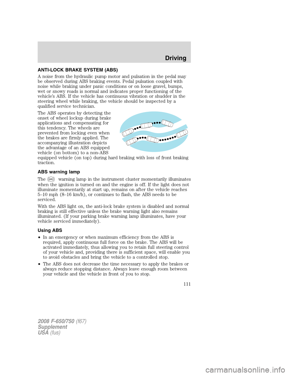
The ABS operates by detecting the
onset of wheel lockup during brake
applications and compensating for
this tendency. The wheels are
prevented from locking even when
the brakes are firmly applied. The
accompanying illustration depicts
the advantage of an ABS equipped
vehicle (on bottom) to a non-ABS
equipped vehicle (on top) during hard braking with loss of front braking
traction.
ABS warning lamp
The
ABSwarning lamp in the instrument cluster momentarily illuminates
when the ignition is turned on and the engine is off. If the light does not
illuminate momentarily at start up, remains on after the vehicle reaches
5–10 mph (8–16 km/h), or continues to flash, the ABS needs to be
serviced.
With the ABS light on, the anti-lock brake system is disabled and normal
braking is still effective unless the brake warning light also remains
illuminated. (If your parking brake warning lamp illuminates, have your
vehicle serviced immediately).
Using ABS
•In an emergency or when maximum efficiency from the ABS is
required, apply continuous full force on the brake. The ABS will be
activated immediately, thus allowing you to retain full steering control
of your vehicle and, providing there is sufficient space, will enable you
to avoid obstacles and bring the vehicle to a controlled stop.
•The ABS does not decrease the time necessary to apply the brakes or
always reduce stopping distance. Always leave enough room between
your vehicle and the vehicle in front of you to stop.
2008 F-650/750(f67)
Supplement
USA(fus)
Driving
111
Page 115 of 273
Tractor-trailer connections
To reduce the risk of personal injury, use extreme caution when
making brake and light connections. Inclement weather and
accumulated road contamination deposits on handhold and stepping
surfaces require extra care to avoid slip and falls. Provide adequate
lighting of working areas.
Do not climb on the back of the tractor unless it has been
provided with a deck plate and handholds. Use a three-point
stance when climbing up and down from a deck plate. Do not jump
from the vehicle. Whenever possible, make all connections while
standing on the ground.
Connecting and disconnecting a trailer with air suspension
When connecting to a trailer:
•Press the lower portion of the switch and air will exhaust from the air
suspension system.
•After making the connection to the trailer, press the upper portion of
the switch, then raise the landing gear.
When disconnecting the trailer:
•Lower the landing gear, then press the lower portion of the switch.
•Disconnect the brake hoses, trailer-side and rear light connectors,
then pull the release lever on the fifth wheel.
The upper portion of the switch must be pressed before operating with a
trailer or operating in the bobtail mode.
Suspension conversions
It is not recommended, or approved, that suspension conversions be
performed. However, it is understood that, on occasion, aftermarket
add-on suspensions are installed by others on the truck chassis which
allow operator control for weight transfer from other axles (i.e., air lift
axles).
When operating a loaded vehicle, the driver must keep all
adjustable axles on the ground at all times, supporting their
share of the vehicle’s load. Failure to do so can overload other axles,
tires, wheels, springs, steering components, brakes and frames,
resulting in early component failure, loss of vehicle control, possible
property damage and personal injury.
2008 F-650/750(f67)
Supplement
USA(fus)
Driving
114
Page 126 of 273
Some Dana/Spicer drive axles have a driver-controlled differential lock.
The differential lock can lock or unlock the differential when the vehicle
is moving or stopped. When extra traction is required, the differential
lock will provide full power to both axles.
When the differential is locked, the vehicle’s turning radius will increase
(vehicle will “under-steer”)
The differential can be locked or unlocked when the vehicle is moving at
a constant speed of less than 25 mph (40 km/h) and while the wheels
are not slipping. The differential must not be locked when the vehicle is
traveling down steep grades and traction is minimal.
Note:Never use the differential lock at vehicle speeds above 25 mph
(40 km/h).
Note:The driver-controlled differential lock function will vary with some
transmissions.
•Vehicles equipped with an Allison 3000 Series transmission:The
differential lock and differential lock light will automatically disengage
at speeds above 25 mph (40 km/h). The differential lock will remain
off until either the vehicle is restarted or the differential lock switch is
turned off then back on.
•Vehicles equipped with a 5–speed, 6–speed or 7–speed manual:
The differential lock and differential lock light will automatically
disengage at speeds above 25 mph (40 km/h). The differential lock
will remain off until either the vehicle is restarted or the differential
lock switch is turned off then back on.
Axle conversions
It is not recommended, or approved, for axle conversions to be
performed. However, it is understood that, on occasion, aftermarket
add-on axles are installed by others on the truck chassis which allow
operator control for weight transfer from other axles (i.e., air lift axles).
When operating a loaded vehicle, the driver must keep all
adjustable axles on the ground at all times, supporting their
share of the vehicle’s load. Failure to do so can overload other axles,
tires, wheels, springs, steering components, brakes and frames,
resulting in early component failure, loss of vehicle control, possible
property damage and personal injury.
TWO-SPEED REAR AXLE (IF EQUIPPED)
A two-speed rear axle allows the driver to select a LO range for greater
pulling power and a HI range for greater road speed and fuel economy.
2008 F-650/750(f67)
Supplement
USA(fus)
Driving
125
Page 136 of 273

HAZARD FLASHER
The hazard flasher control is located
on the steering column, just behind
the steering wheel. The hazard
flashers will operate when the
ignition is off.
Push in the flasher control and all
front and rear direction signals will
flash. Press the flasher control again
to turn them off. Use it when your
vehicle is disabled and is creating a
safety hazard for other motorists.
Note:With extended use, the flasher may run down your battery.
FUSING
If electrical components in the vehicle are not working, a fuse may have
blown. Blown fuses are identified by a broken wire within the fuse.
Check the appropriate fuses before replacing any electrical components.
Note:Always replace a fuse with one that has the specified amperage
rating. Using a fuse with a higher amperage rating can cause severe wire
damage and could start a fire.
2008 F-650/750(f67)
Supplement
USA(fus)
Roadside Emergencies
135
Page 162 of 273
vehicle at least once a year. Remember that regular maintenance and
replacement of worn components will usually prevent serious problems
from developing later.
Making modifications to various parts, components and systems
of the vehicle, such as brake and steering systems can adversely
affect the quality, reliability and operation of your vehicle and could
result in property damage, personal injury or death. Such modifications
must be avoided.
The lubrication intervals present a good opportunity to inspect the
vehicle. It is suggested that the various points listed herein be checked
at the lubrication or other recommended intervals.
Failure to properly perform maintenance and servicing
procedures could result in vehicle damage, personal injury or
death.
If the owner/operator of the vehicle is a skilled technician and intends on
performing the vehicle maintenance and service, he is strongly urged to
purchase a service manual.
Take care when performing any maintenance, system check or
service on your vehicle. Some of the materials may also be
hazardous if used, serviced or handled improperly and could result in
property damage, personal injury or death.
Air conditioning system checks
Have your air conditioning system checked each spring. The refrigerant
charge, cleanliness of the condenser-evaporator cores and belt condition
are essential to air conditioning performance.
When the air conditioning system is being used daily, remove the fresh
air filter (if equipped) once each season and check for dirt, lint, etc.
Replace the filter if necessary. Vehicles operating in unusually dusty
conditions may require inspecting and replacing the fresh air filter more
often.
Front axle - general service information
Maintaining the front axle alignment to specifications is very important
and should only be performed by a qualified technician. Toe-in
adjustment is particularly important with radial tires.
2008 F-650/750(f67)
Supplement
USA(fus)
Maintenance and Specifications
161
Page 167 of 273
Note:If brake fluid requires attention to maintain a proper master
cylinder level, this is an indication of either severe operation (pad wear)
or fluid system leakage. A more frequent and thorough brake inspection
will be required.
Hydraulic brakes - fluid precautions
The HydroMax brake system consists of two completely separate
hydraulic systems operating with two different and incompatible fluids;
power steering fluid and hydraulic brake fluid. Failure to observe
precautions preventing the contamination of either system with fluid
from the other will result in swelling and deterioration of rubber parts
leading to reduced brake performance and eventual brake failure.
To avoid fluid contamination, the following should always be observed:
1. Use only fluids specified (or equivalent) and properly identified.
2. Add fluids only to the following locations:
•Power steering fluid to the power steering fluid pump reservoir
•Brake fluid to the brake master cylinder
Hydraulic brakes - brake lines, hoses and fittings
Inspect these components every 4,000 miles (6,400 km).
•Check lines for kinks, dents, corrosion or rupture.
•Check hoses for abrasions, kinks, soft spots or rupture, collapse,
cracks, twists or loose frame supports. When replacing a hose, be sure
there is adequate clearance to the hose to avoid an abrasion to the
new hose.
•Examine all connections for leaks.
•Repair or replace brake line tubes, hoses or fittings as required.
Driveline parking brake
Parking brake adjustment should only be performed by a qualified
technician, and in accordance with the instructions in the service
manual.
Use wheel chocks and exercise caution when inspecting under
the vehicle. A vehicle roll-away could result in property damage,
personal injury or death.
Catalytic converter
If your diesel engine is equipped with a catalytic converter, it is
important to review the maintenance schedule to ensure proper
2008 F-650/750(f67)
Supplement
USA(fus)
Maintenance and Specifications
166
Page 168 of 273
functioning of the catalytic converter. Also, take precautions not to
damage the catalytic converter when servicing your engine or storing
your vehicle.
Note:If your vehicle is equipped with a catalytic converter/muffler,do
notblend waste oil with Diesel fuel. Operate only on ultra low sulfur
(less than 15 parts per million sulfur) diesel fuel with a cetane value of
45 or higher.
Air induction system
Once each year, perform a complete inspection of the air induction
system. In areas where road salt is used, the inspection consists of
disassembling the joints of each aluminum component and inspecting for
salt build-up, presence of chlorine that can cause aluminum particles to
flake off and enter the engine combustion chambers.
If evidence of corrosion is found (usually at the pipe connections), use a
wire brush to clean the inside of the pipes and inside the rubber hoses.
If the intake pipes are pitted at the joint ends, use Motorcraft Silicone
Gasket and Sealant TA-30 to seal the joints. Be certain that no excess
material is on the inside of the pipes that can be pulled into the engine.
If the service condition of the pipes, hoses or clamps is questionable,
replace the defective part(s).
Be sure that prior to reassembly all dust and debris has been cleaned out
of the pipes and couplings with a clean, damp rag.
When performing maintenance to any turbocharged engine with
engine air inlet piping disconnected, keep loose clothing, jewelry
and long hair away from the engine air inlet piping. A turbocharger
compressor air inlet protective shield should be installed over the
turbocharger air inlet to reduce the risk of personal injury or death.
Steering - general inspection
•Ask your service technician to examine the steering mechanism. Only
minor adjustments may be necessary.
•Check tie rod, drag link end clamp bolts and ball joints. They must be
tight.
•Check for installation and spread of cotter pins and tightness of nuts
at both ends of the tie rod and drag link.
•Check that pitman arm (steering arm at steering gear) mounting is
tight and locked. Check system for leaks or hose chafing. Repair at
once.
2008 F-650/750(f67)
Supplement
USA(fus)
Maintenance and Specifications
167