instrument panel FORD F650 2009 12.G Owners Manual
[x] Cancel search | Manufacturer: FORD, Model Year: 2009, Model line: F650, Model: FORD F650 2009 12.GPages: 276, PDF Size: 1.75 MB
Page 46 of 276
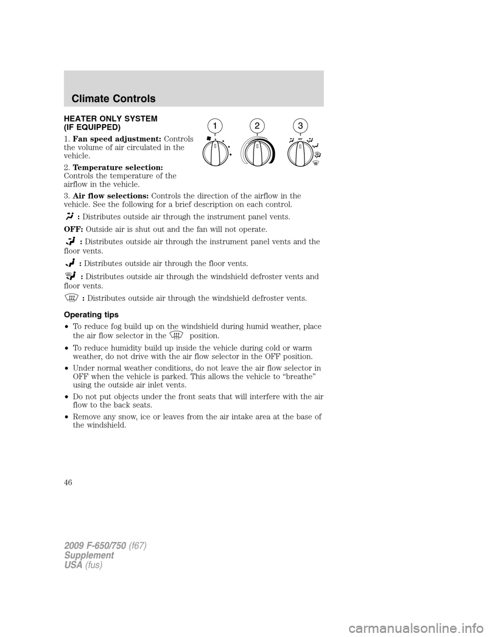
HEATER ONLY SYSTEM
(IF EQUIPPED)
1.Fan speed adjustment:Controls
the volume of air circulated in the
vehicle.
2.Temperature selection:
Controls the temperature of the
airflow in the vehicle.
3.Air flow selections:Controls the direction of the airflow in the
vehicle. See the following for a brief description on each control.
:Distributes outside air through the instrument panel vents.
OFF:Outside air is shut out and the fan will not operate.
:Distributes outside air through the instrument panel vents and the
floor vents.
:Distributes outside air through the floor vents.
:Distributes outside air through the windshield defroster vents and
floor vents.
:Distributes outside air through the windshield defroster vents.
Operating tips
•To reduce fog build up on the windshield during humid weather, place
the air flow selector in the
position.
•To reduce humidity build up inside the vehicle during cold or warm
weather, do not drive with the air flow selector in the OFF position.
•Under normal weather conditions, do not leave the air flow selector in
OFF when the vehicle is parked. This allows the vehicle to “breathe”
using the outside air inlet vents.
•Do not put objects under the front seats that will interfere with the air
flow to the back seats.
•Remove any snow, ice or leaves from the air intake area at the base of
the windshield.
2009 F-650/750(f67)
Supplement
USA(fus)
Climate Controls
46
Page 47 of 276
To aid in side window defogging/demisting in cold weather:
1. Select
.
2. Set the temperature control to full heat.
3. Set the fan speed to its highest speed.
4. Direct the outer instrument panel vents towards the side windows.
To increase airflow to the outer instrument panel vents, close the vents
located in the middle of the instrument panel.
WARNING:Do not place objects on top of the instrument panel
as these objects may become projectiles in a collision or sudden
stop.
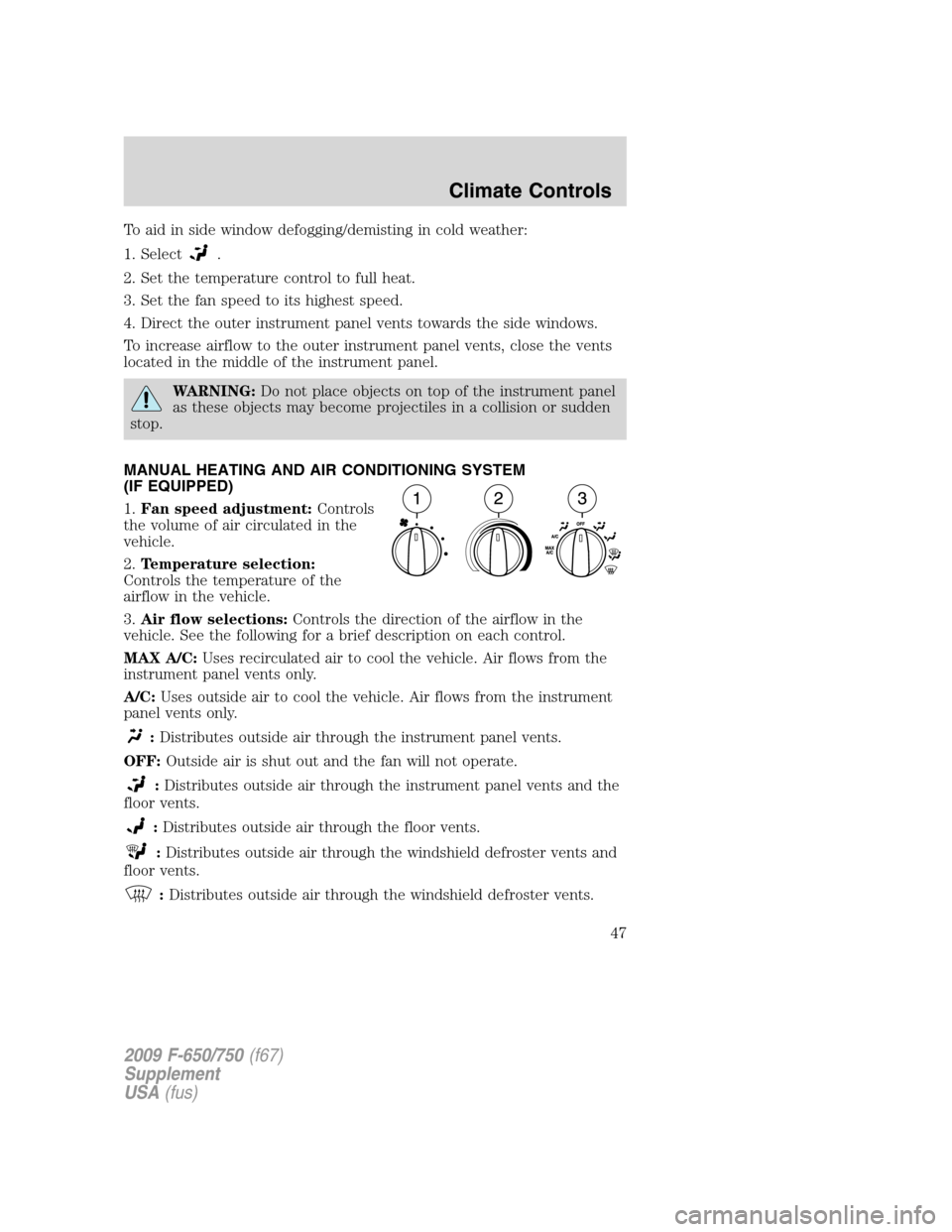
MANUAL HEATING AND AIR CONDITIONING SYSTEM
(IF EQUIPPED)
1.Fan speed adjustment:Controls
the volume of air circulated in the
vehicle.
2.Temperature selection:
Controls the temperature of the
airflow in the vehicle.
3.Air flow selections:Controls the direction of the airflow in the
vehicle. See the following for a brief description on each control.
MAX A/C:Uses recirculated air to cool the vehicle. Air flows from the
instrument panel vents only.
A/C:Uses outside air to cool the vehicle. Air flows from the instrument
panel vents only.
:Distributes outside air through the instrument panel vents.
OFF:Outside air is shut out and the fan will not operate.
:Distributes outside air through the instrument panel vents and the
floor vents.
:Distributes outside air through the floor vents.
:Distributes outside air through the windshield defroster vents and
floor vents.
:Distributes outside air through the windshield defroster vents.
2009 F-650/750(f67)
Supplement
USA(fus)
Climate Controls
47
Page 48 of 276
Operating tips
•To reduce fog build up on the windshield during humid weather, place
the air flow selector in the
position.
•To reduce humidity build up inside the vehicle: do not drive with the
air flow selector in the OFF or MAX A/C position.
•Under normal weather conditions, do not leave the air flow selector in
OFF or MAX A/C when the vehicle is parked. This allows the vehicle
to “breathe” using the outside air inlet vents.
•Do not put objects under the front seats that will interfere with the
airflow to the back seats.
•Remove any snow, ice or leaves from the air intake area at the base of
the windshield.
To aid in side window defogging/demisting in cold weather:
1. Select
.
2. Select A/C.
3. Modulate the temperature control to maintain comfort.
4. Set the fan speed to its highest speed.
5. Direct the outer instrument panel vents towards the side windows.
To increase airflow to the outer instrument panel vents, close the vents
located in the middle of the instrument panel.
WARNING:Do not place objects on top of the instrument panel
as these objects may become projectiles in a collision or sudden
stop.
2009 F-650/750(f67)
Supplement
USA(fus)
Climate Controls
48
Page 49 of 276
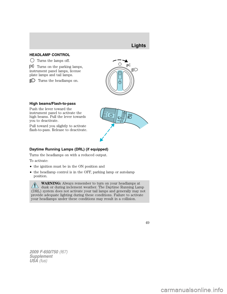
HEADLAMP CONTROL
Turns the lamps off.
Turns on the parking lamps,
instrument panel lamps, license
plate lamps and tail lamps.
Turns the headlamps on.
High beams/Flash-to-pass
Push the lever toward the
instrument panel to activate the
high beams. Pull the lever towards
you to deactivate.
Pull toward you slightly to activate
flash-to-pass. Release to deactivate.
Daytime Running Lamps (DRL) (if equipped)
Turns the headlamps on with a reduced output.
To activate:
•the ignition must be in the ON position and
•the headlamp control is in the OFF, parking lamp or autolamp
position.
WARNING:Always remember to turn on your headlamps at
dusk or during inclement weather. The Daytime Running Lamp
(DRL) system does not activate your tail lamps and generally may not
provide adequate lighting during these conditions. Failure to activate
your headlamps under these conditions may result in a collision.
2009 F-650/750(f67)
Supplement
USA(fus)
Lights
49
Page 50 of 276
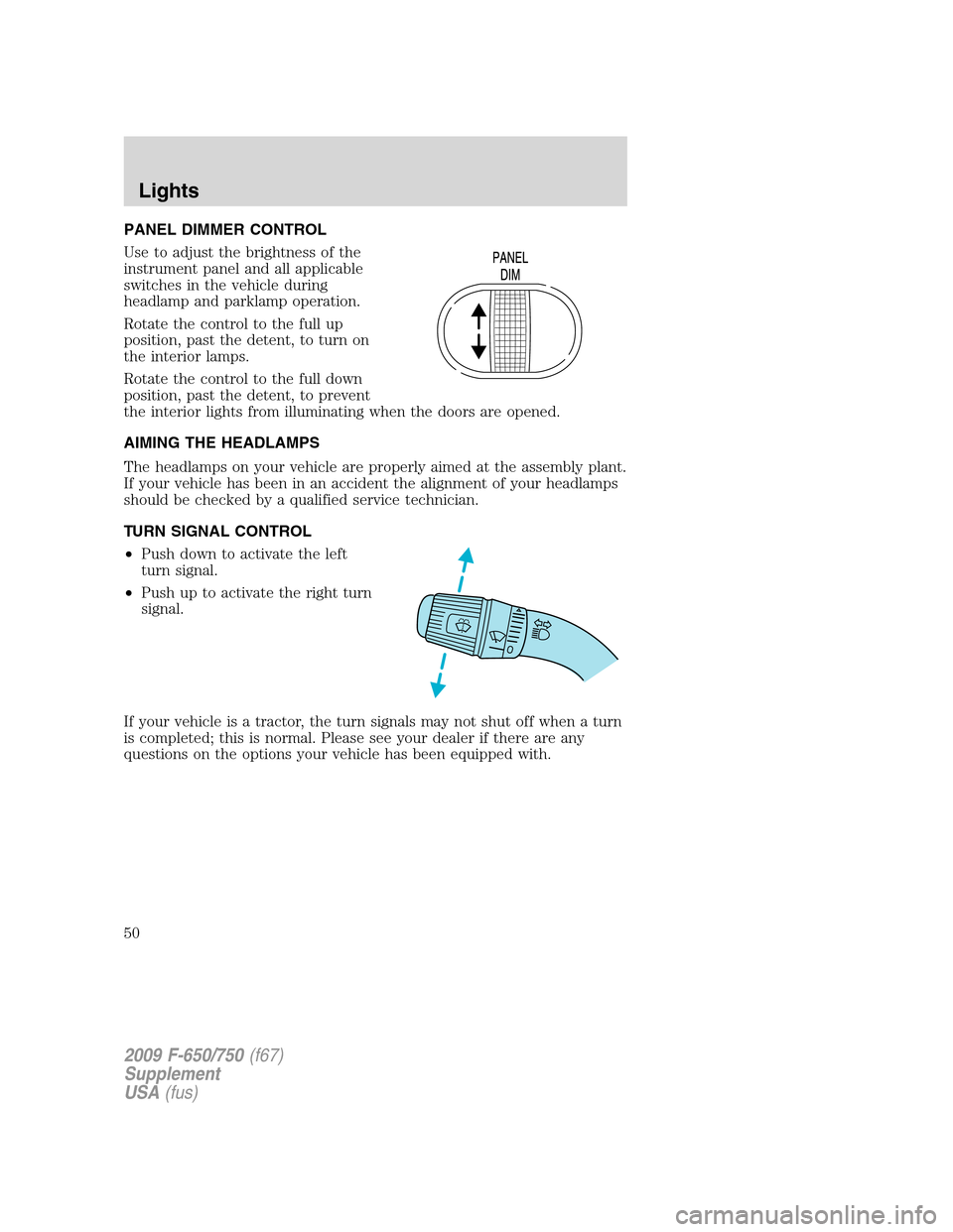
PANEL DIMMER CONTROL
Use to adjust the brightness of the
instrument panel and all applicable
switches in the vehicle during
headlamp and parklamp operation.
Rotate the control to the full up
position, past the detent, to turn on
the interior lamps.
Rotate the control to the full down
position, past the detent, to prevent
the interior lights from illuminating when the doors are opened.
AIMING THE HEADLAMPS
The headlamps on your vehicle are properly aimed at the assembly plant.
If your vehicle has been in an accident the alignment of your headlamps
should be checked by a qualified service technician.
TURN SIGNAL CONTROL
•Push down to activate the left
turn signal.
•Push up to activate the right turn
signal.
If your vehicle is a tractor, the turn signals may not shut off when a turn
is completed; this is normal. Please see your dealer if there are any
questions on the options your vehicle has been equipped with.
2009 F-650/750(f67)
Supplement
USA(fus)
Lights
50
Page 51 of 276
INTERIOR LAMPS
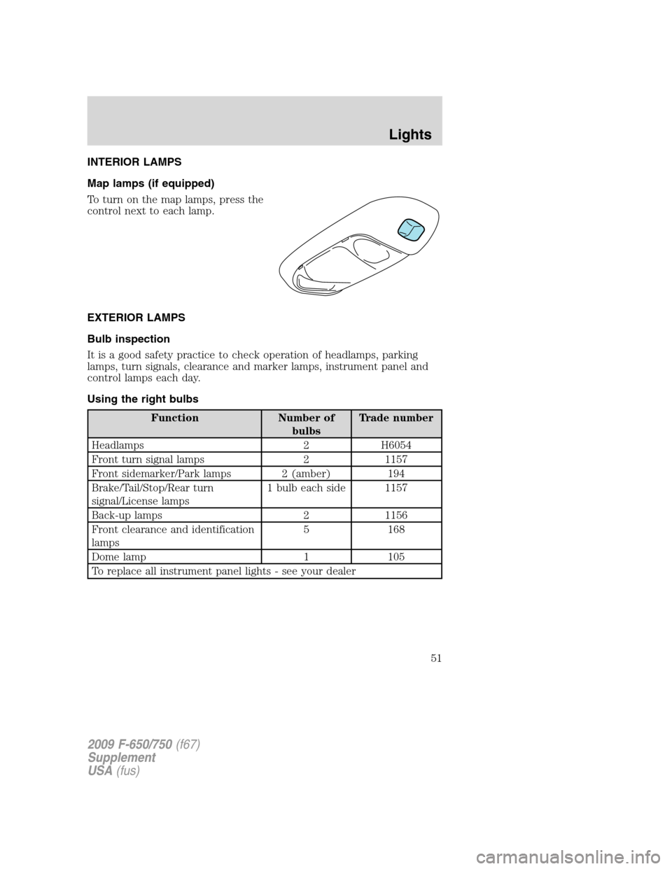
Map lamps (if equipped)
To turn on the map lamps, press the
control next to each lamp.
EXTERIOR LAMPS
Bulb inspection
It is a good safety practice to check operation of headlamps, parking
lamps, turn signals, clearance and marker lamps, instrument panel and
control lamps each day.
Using the right bulbs
Function Number of
bulbsTrade number
Headlamps 2 H6054
Front turn signal lamps 2 1157
Front sidemarker/Park lamps 2 (amber) 194
Brake/Tail/Stop/Rear turn
signal/License lamps1 bulb each side 1157
Back-up lamps 2 1156
Front clearance and identification
lamps5 168
Dome lamp 1 105
To replace all instrument panel lights - see your dealer
2009 F-650/750(f67)
Supplement
USA(fus)
Lights
51
Page 55 of 276
WARNING:Never adjust the steering wheel when the vehicle is
moving.
AUXILIARY POWER POINT
Power outlets are designed for accessory plugs only. Do not insert
any other object in the power outlet as this will damage the
outlet and blow the fuse. Do not hang any type of accessory or
accessory bracket from the plug. Improper use of the power
outlet can cause damage not covered by your warranty.
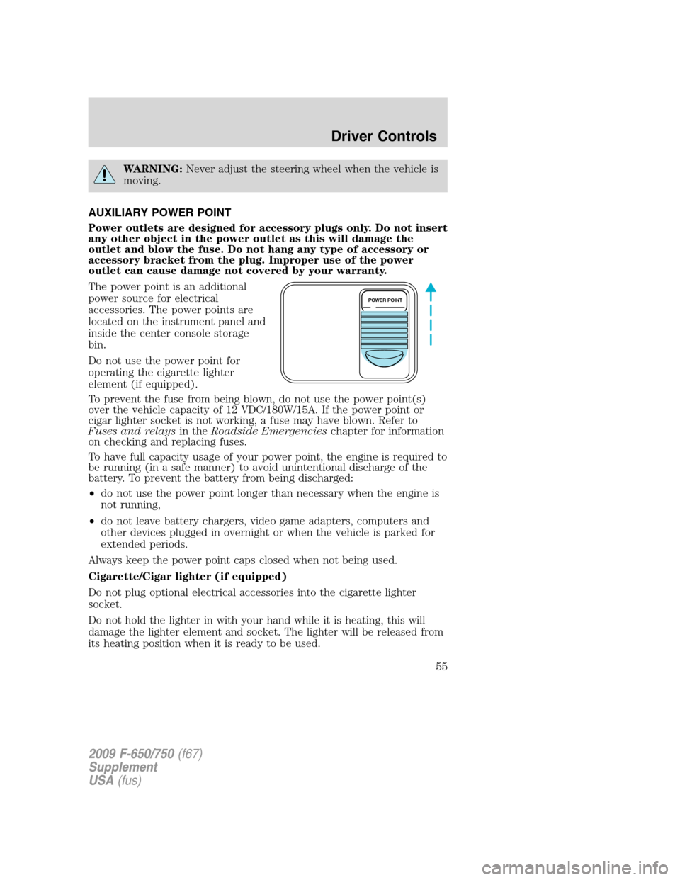
The power point is an additional
power source for electrical
accessories. The power points are
located on the instrument panel and
inside the center console storage
bin.
Do not use the power point for
operating the cigarette lighter
element (if equipped).
To prevent the fuse from being blown, do not use the power point(s)
over the vehicle capacity of 12 VDC/180W/15A. If the power point or
cigar lighter socket is not working, a fuse may have blown. Refer to
Fuses and relaysin theRoadside Emergencieschapter for information
on checking and replacing fuses.
To have full capacity usage of your power point, the engine is required to
be running (in a safe manner) to avoid unintentional discharge of the
battery. To prevent the battery from being discharged:
•do not use the power point longer than necessary when the engine is
not running,
•do not leave battery chargers, video game adapters, computers and
other devices plugged in overnight or when the vehicle is parked for
extended periods.
Always keep the power point caps closed when not being used.
Cigarette/Cigar lighter (if equipped)
Do not plug optional electrical accessories into the cigarette lighter
socket.
Do not hold the lighter in with your hand while it is heating, this will
damage the lighter element and socket. The lighter will be released from
its heating position when it is ready to be used.
POWER POINT
2009 F-650/750(f67)
Supplement
USA(fus)
Driver Controls
55
Page 111 of 276
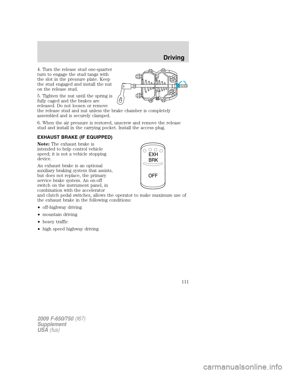
4. Turn the release stud one-quarter
turn to engage the stud tangs with
the slot in the pressure plate. Keep
the stud engaged and install the nut
on the release stud.
5. Tighten the nut until the spring is
fully caged and the brakes are
released. Do not loosen or remove
the release stud and nut unless the brake chamber is completely
assembled and is securely clamped.
6. When the air pressure is restored, unscrew and remove the release
stud and install in the carrying pocket. Install the access plug.
EXHAUST BRAKE (IF EQUIPPED)
Note:The exhaust brake is
intended to help control vehicle
speed; it is not a vehicle stopping
device.
An exhaust brake is an optional
auxiliary braking system that assists,
but does not replace, the primary
service brake system. An on-off
switch on the instrument panel, in
combination with the accelerator
and clutch pedal switches, allows the operator to make maximum use of
the exhaust brake in the following conditions:
•off-highway driving
•mountain driving
•heavy traffic
•high speed highway driving
2009 F-650/750(f67)
Supplement
USA(fus)
Driving
111
Page 114 of 276
Note:Installing an exhaust or auxiliary brake does not necessarily
protect the engine from exceeding maximum governed speed. The
primary brakes should be used to make sure the engine never exceeds
maximum governed speed under any conditions.
TRAILER BRAKE HAND CONTROL (IF EQUIPPED)
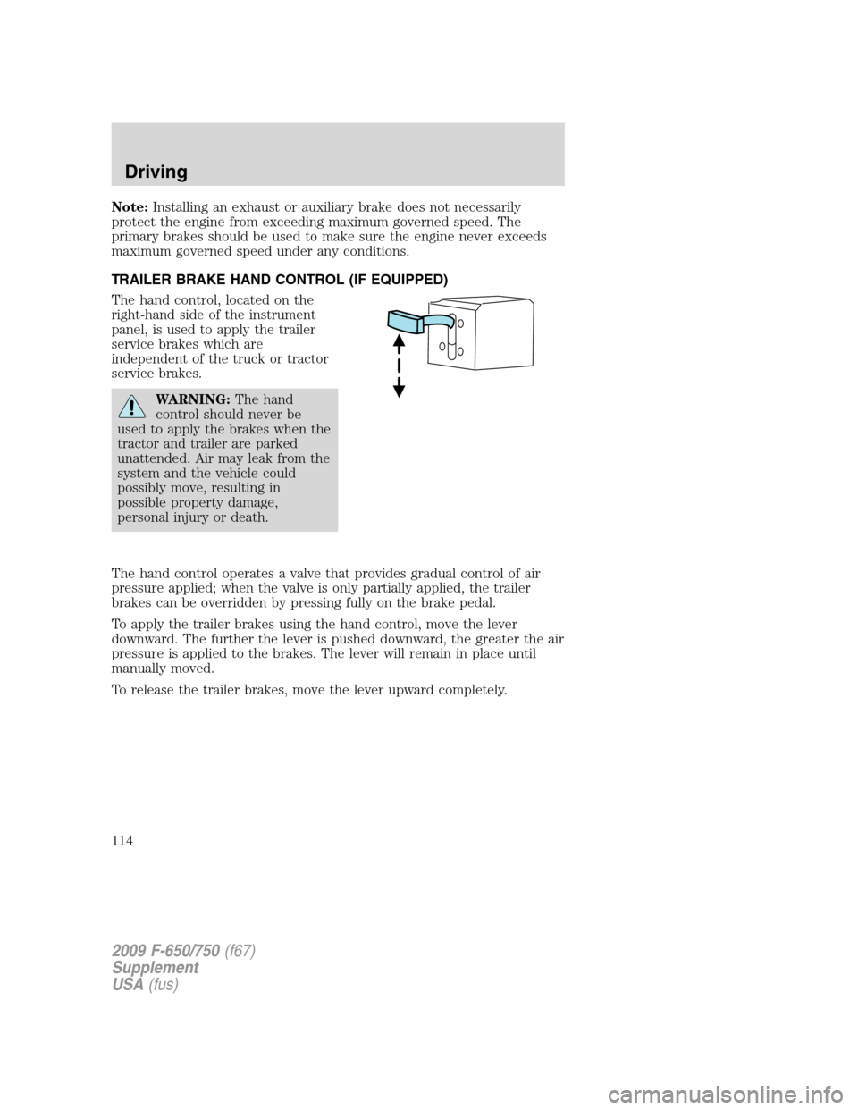
The hand control, located on the
right-hand side of the instrument
panel, is used to apply the trailer
service brakes which are
independent of the truck or tractor
service brakes.
WARNING:The hand
control should never be
used to apply the brakes when the
tractor and trailer are parked
unattended. Air may leak from the
system and the vehicle could
possibly move, resulting in
possible property damage,
personal injury or death.
The hand control operates a valve that provides gradual control of air
pressure applied; when the valve is only partially applied, the trailer
brakes can be overridden by pressing fully on the brake pedal.
To apply the trailer brakes using the hand control, move the lever
downward. The further the lever is pushed downward, the greater the air
pressure is applied to the brakes. The lever will remain in place until
manually moved.
To release the trailer brakes, move the lever upward completely.
2009 F-650/750(f67)
Supplement
USA(fus)
Driving
114
Page 120 of 276
TRACTION CONTROL™ (IF EQUIPPED)
Your vehicle may be equipped with a Traction Control™ system. This
system helps you maintain the stability and steerability of your vehicle,
especially on slippery road surfaces such as snow- or ice-covered roads
and gravel roads, by reducing engine power and/or selectively applying
the rear brakes. The system will allow your vehicle to make better use of
available traction in these conditions.
Note:The traction control system will not apply the brakes when the
vehicle speed is above 25 mph (40 km/h).
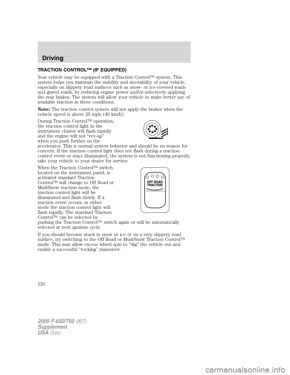
During Traction Control™ operation,
the traction control light in the
instrument cluster will flash rapidly
and the engine will not “rev-up”
when you push further on the
accelerator. This is normal system behavior and should be no reason for
concern. If the traction control light does not flash during a traction
control event or stays illuminated, the system is not functioning properly,
take your vehicle to your dealer for service.
When the Traction Control™ switch,
located on the instrument panel, is
activated standard Traction
Control™ will change to Off Road or
Mud/Snow traction mode, the
traction control light will be
illuminated and flash slowly. If a
traction event occurs, in either
mode the traction control light will
flash rapidly. The standard Traction
Control™ can be selected by
pushing the Traction Control™ switch again or will be automatically
selected at next ignition cycle.
If you should become stuck in snow or ice or on a very slippery road
surface, try switching to the Off Road or Mud/Snow Traction Control™
mode. This may allow excess wheel spin to “dig” the vehicle out and
enable a successful “rocking” maneuver.
2009 F-650/750(f67)
Supplement
USA(fus)
Driving
120