heater FORD F650 2010 12.G Owners Manual
[x] Cancel search | Manufacturer: FORD, Model Year: 2010, Model line: F650, Model: FORD F650 2010 12.GPages: 274, PDF Size: 1.51 MB
Page 1 of 274
Introduction 4
Safety and environment protection 4
Vehicle Inspection Guide 11
Instrument Cluster 22
Warning lights and chimes 22
Gauges 28
Entertainment Systems 33
AM/FM stereo 33
AM/FM stereo with in-dash six CD 40
Climate Controls 46
Heater only 46
Manual heating and air conditioning 47
Lights 49
Headlamps 49
Turn signal control 50
Interior lamps 51
Bulb replacement 51
Driver Controls 54
Windshield wiper/washer control 54
Steering wheel adjustment 54
Power windows 56
Mirrors 57
Speed control 59
Table of Contents
1
2010 F-650/750(f67)
Supplement(supplement), 1st Printing
USA(fus)
Page 24 of 274
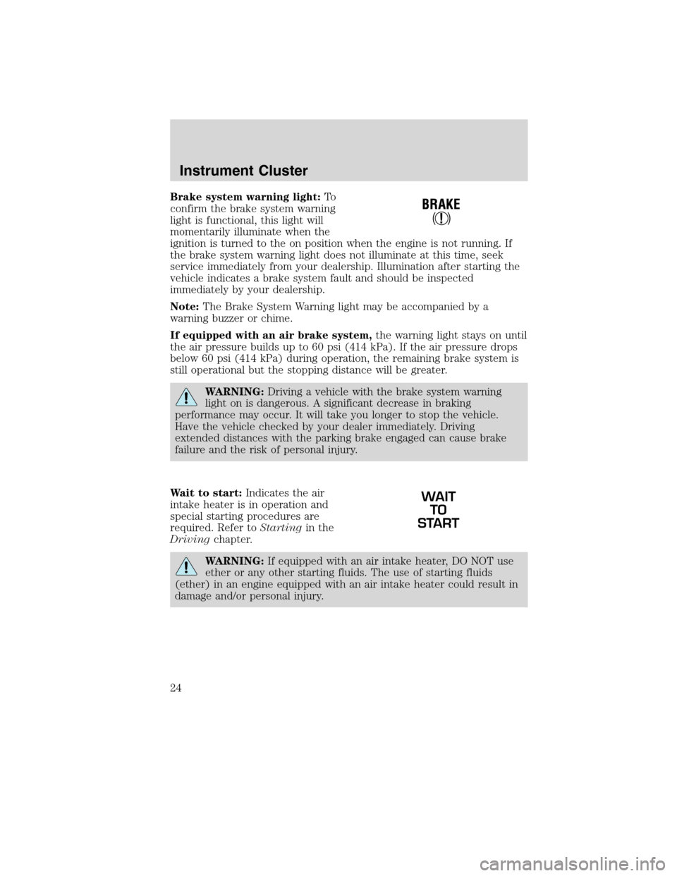
Brake system warning light:To
confirm the brake system warning
light is functional, this light will
momentarily illuminate when the
ignition is turned to the on position when the engine is not running. If
the brake system warning light does not illuminate at this time, seek
service immediately from your dealership. Illumination after starting the
vehicle indicates a brake system fault and should be inspected
immediately by your dealership.
Note:The Brake System Warning light may be accompanied by a
warning buzzer or chime.
If equipped with an air brake system,the warning light stays on until
the air pressure builds up to 60 psi (414 kPa). If the air pressure drops
below 60 psi (414 kPa) during operation, the remaining brake system is
still operational but the stopping distance will be greater.
WARNING:Driving a vehicle with the brake system warning
light on is dangerous. A significant decrease in braking
performance may occur. It will take you longer to stop the vehicle.
Have the vehicle checked by your dealer immediately. Driving
extended distances with the parking brake engaged can cause brake
failure and the risk of personal injury.
Wait to start:Indicates the air
intake heater is in operation and
special starting procedures are
required. Refer toStartingin the
Drivingchapter.
WARNING:If equipped with an air intake heater, DO NOT use
ether or any other starting fluids. The use of starting fluids
(ether) in an engine equipped with an air intake heater could result in
damage and/or personal injury.
WAIT
TO
START
Instrument Cluster
24
2010 F-650/750(f67)
Supplement(supplement), 1st Printing
USA(fus)
Page 46 of 274
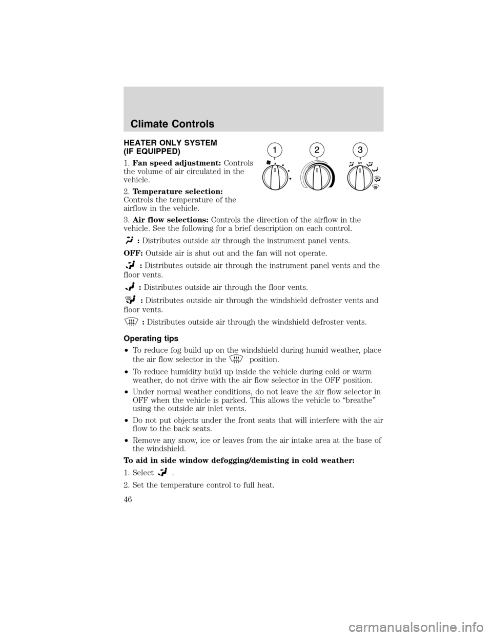
HEATER ONLY SYSTEM
(IF EQUIPPED)
1.Fan speed adjustment:Controls
the volume of air circulated in the
vehicle.
2.Temperature selection:
Controls the temperature of the
airflow in the vehicle.
3.Air flow selections:Controls the direction of the airflow in the
vehicle. See the following for a brief description on each control.
:Distributes outside air through the instrument panel vents.
OFF:Outside air is shut out and the fan will not operate.
:Distributes outside air through the instrument panel vents and the
floor vents.
:Distributes outside air through the floor vents.
:Distributes outside air through the windshield defroster vents and
floor vents.
:Distributes outside air through the windshield defroster vents.
Operating tips
•To reduce fog build up on the windshield during humid weather, place
the air flow selector in the
position.
•To reduce humidity build up inside the vehicle during cold or warm
weather, do not drive with the air flow selector in the OFF position.
•Under normal weather conditions, do not leave the air flow selector in
OFF when the vehicle is parked. This allows the vehicle to “breathe”
using the outside air inlet vents.
•Do not put objects under the front seats that will interfere with the air
flow to the back seats.
•Remove any snow, ice or leaves from the air intake area at the base of
the windshield.
To aid in side window defogging/demisting in cold weather:
1. Select
.
2. Set the temperature control to full heat.
Climate Controls
46
2010 F-650/750(f67)
Supplement(supplement), 1st Printing
USA(fus)
Page 92 of 274
Note:When starting the engine, do not press the accelerator as engine
damage may result.
1. Ensure headlamps and all accessories are turned off, the parking
brake is applied and the transmission is in the neutral position (or P
[Park] for Allison 2200 transmissions).
2. Turn the key to the on position, but do not start the engine.
In cooler weather, the air intake
heater may activate the WAIT TO
START light in the instrument
cluster. If the WAIT TO START light
illuminates,do notcrank the engine
until the light goes off.
WARNING:If equipped with an air intake heater, DO NOT use
ether or any other starting fluids. The use of starting fluids
(ether) in an engine equipped with an air intake heater could cause an
explosion and result in property damage and/or personal injury.
3. When the WAIT TO START light turns off, turn the key to the start
position; when the engine starts, release the key.
If the engine does not start after 30 seconds of cranking, allow two
minutes for the starter to cool before trying again. Excessive cranking
may damage the starter.
After the engine starts:
•On some engines, the WAIT TO
START light should illuminate
after the engine starts. Allow the
engine to idle about three
minutes or until the engine
coolant temperature gauge begins to rise. Maintain idle speed until the
WAIT TO START light cycles off to indicate the air intake heater has
shut off (approximately six minutes). Operating the engine at higher
speeds will reduce the effectiveness of the air inlet heater.
WAIT
TO
START
WAIT
TO
START
Driving
92
2010 F-650/750(f67)
Supplement(supplement), 1st Printing
USA(fus)
Page 93 of 274
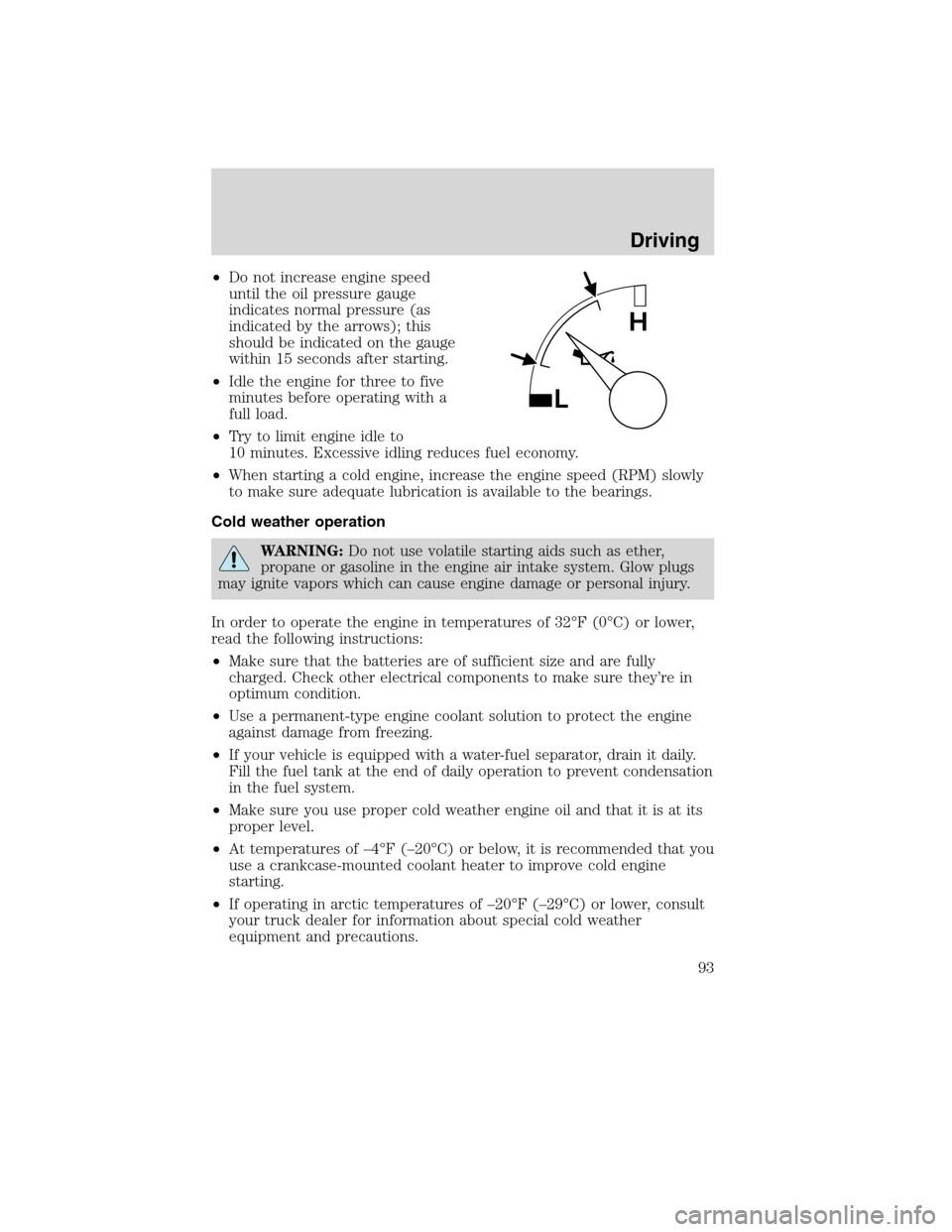
•Do not increase engine speed
until the oil pressure gauge
indicates normal pressure (as
indicated by the arrows); this
should be indicated on the gauge
within 15 seconds after starting.
•Idle the engine for three to five
minutes before operating with a
full load.
•Try to limit engine idle to
10 minutes. Excessive idling reduces fuel economy.
•When starting a cold engine, increase the engine speed (RPM) slowly
to make sure adequate lubrication is available to the bearings.
Cold weather operation
WARNING:Do not use volatile starting aids such as ether,
propane or gasoline in the engine air intake system. Glow plugs
may ignite vapors which can cause engine damage or personal injury.
In order to operate the engine in temperatures of 32°F (0°C) or lower,
read the following instructions:
•Make sure that the batteries are of sufficient size and are fully
charged. Check other electrical components to make sure they’re in
optimum condition.
•Use a permanent-type engine coolant solution to protect the engine
against damage from freezing.
•If your vehicle is equipped with a water-fuel separator, drain it daily.
Fill the fuel tank at the end of daily operation to prevent condensation
in the fuel system.
•Make sure you use proper cold weather engine oil and that it is at its
proper level.
•At temperatures of –4°F (–20°C) or below, it is recommended that you
use a crankcase-mounted coolant heater to improve cold engine
starting.
•If operating in arctic temperatures of –20°F (–29°C) or lower, consult
your truck dealer for information about special cold weather
equipment and precautions.
Driving
93
2010 F-650/750(f67)
Supplement(supplement), 1st Printing
USA(fus)
Page 145 of 274
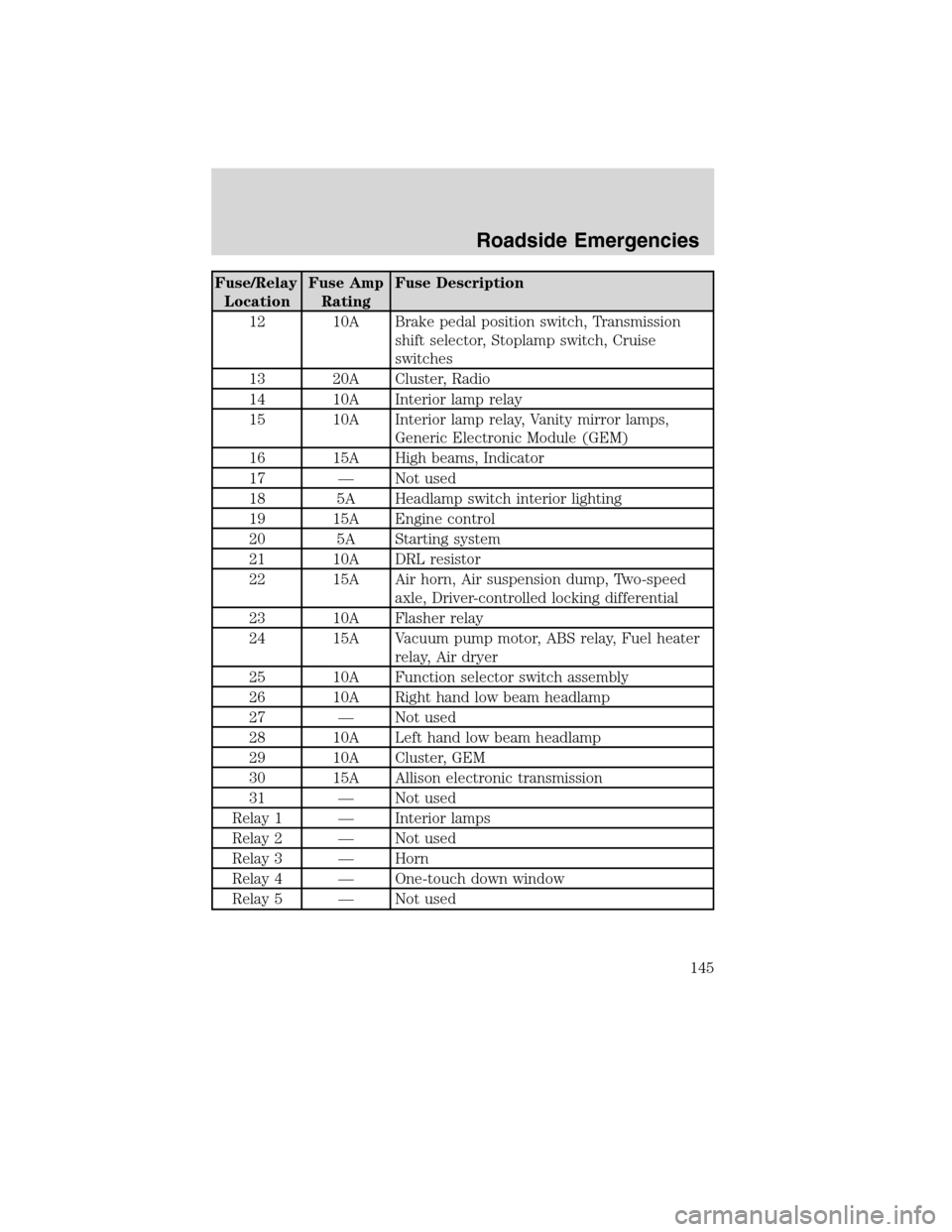
Fuse/Relay
LocationFuse Amp
RatingFuse Description
12 10A Brake pedal position switch, Transmission
shift selector, Stoplamp switch, Cruise
switches
13 20A Cluster, Radio
14 10A Interior lamp relay
15 10A Interior lamp relay, Vanity mirror lamps,
Generic Electronic Module (GEM)
16 15A High beams, Indicator
17 — Not used
18 5A Headlamp switch interior lighting
19 15A Engine control
20 5A Starting system
21 10A DRL resistor
22 15A Air horn, Air suspension dump, Two-speed
axle, Driver-controlled locking differential
23 10A Flasher relay
24 15A Vacuum pump motor, ABS relay, Fuel heater
relay, Air dryer
25 10A Function selector switch assembly
26 10A Right hand low beam headlamp
27 — Not used
28 10A Left hand low beam headlamp
29 10A Cluster, GEM
30 15A Allison electronic transmission
31 — Not used
Relay 1 — Interior lamps
Relay 2 — Not used
Relay 3 — Horn
Relay 4 — One-touch down window
Relay 5 — Not used
Roadside Emergencies
145
2010 F-650/750(f67)
Supplement(supplement), 1st Printing
USA(fus)
Page 146 of 274
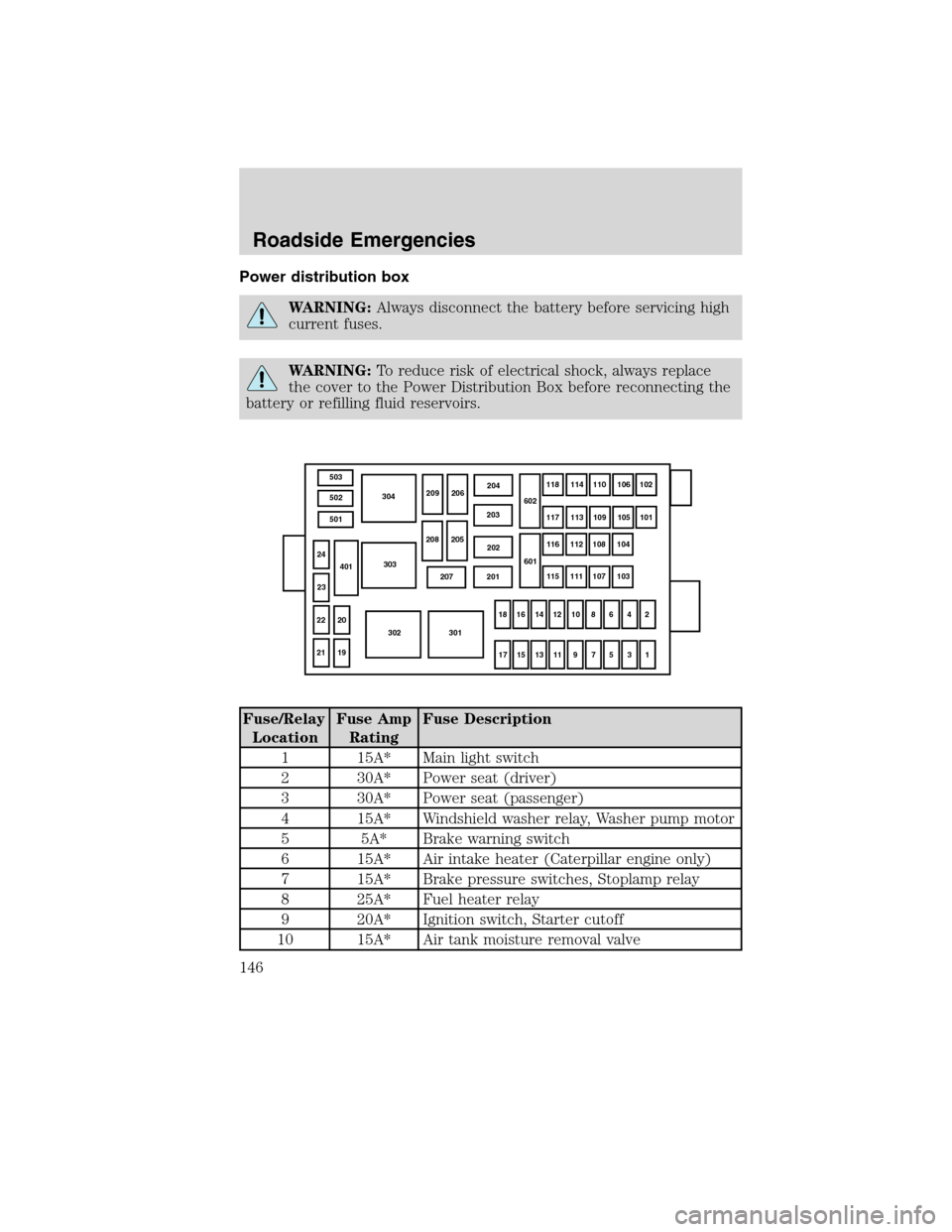
Power distribution box
WARNING:Always disconnect the battery before servicing high
current fuses.
WARNING:To reduce risk of electrical shock, always replace
the cover to the Power Distribution Box before reconnecting the
battery or refilling fluid reservoirs.
Fuse/Relay
LocationFuse Amp
RatingFuse Description
1 15A* Main light switch
2 30A* Power seat (driver)
3 30A* Power seat (passenger)
4 15A* Windshield washer relay, Washer pump motor
5 5A* Brake warning switch
6 15A* Air intake heater (Caterpillar engine only)
7 15A* Brake pressure switches, Stoplamp relay
8 25A* Fuel heater relay
9 20A* Ignition switch, Starter cutoff
10 15A* Air tank moisture removal valve
503
502
501304
303
302 301
2119 22 2024
23401
207 201202 203204
209 206
208 205602
601118114
110106
102
117 113 109105
101
116 112 108104
115 111 107103
18 16
14 12 10 864
2
17 15
13 11 9 753
1
Roadside Emergencies
146
2010 F-650/750(f67)
Supplement(supplement), 1st Printing
USA(fus)
Page 147 of 274
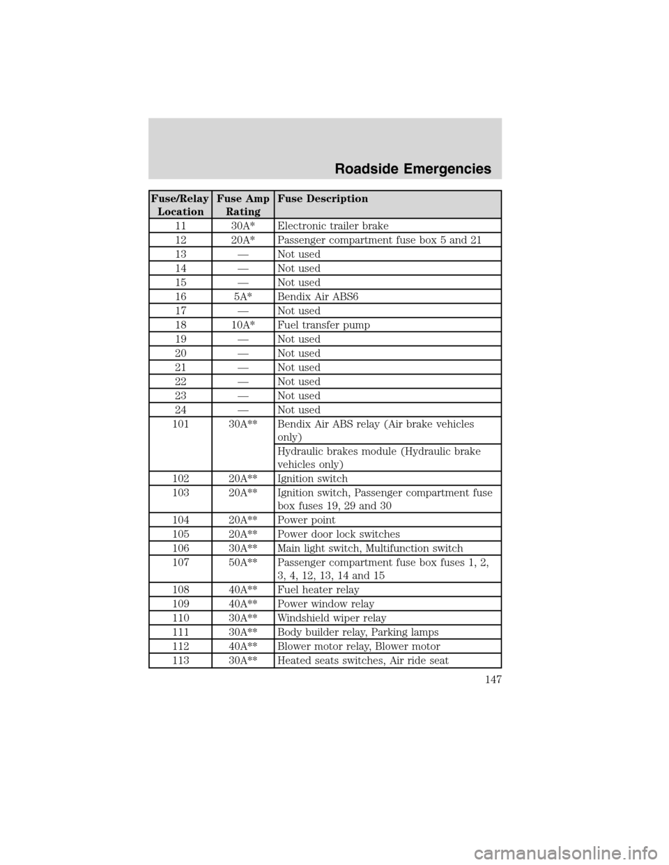
Fuse/Relay
LocationFuse Amp
RatingFuse Description
11 30A* Electronic trailer brake
12 20A* Passenger compartment fuse box 5 and 21
13 — Not used
14 — Not used
15 — Not used
16 5A* Bendix Air ABS6
17 — Not used
18 10A* Fuel transfer pump
19 — Not used
20 — Not used
21 — Not used
22 — Not used
23 — Not used
24 — Not used
101 30A** Bendix Air ABS relay (Air brake vehicles
only)
Hydraulic brakes module (Hydraulic brake
vehicles only)
102 20A** Ignition switch
103 20A** Ignition switch, Passenger compartment fuse
box fuses 19, 29 and 30
104 20A** Power point
105 20A** Power door lock switches
106 30A** Main light switch, Multifunction switch
107 50A** Passenger compartment fuse box fuses 1, 2,
3, 4, 12, 13, 14 and 15
108 40A** Fuel heater relay
109 40A** Power window relay
110 30A** Windshield wiper relay
111 30A** Body builder relay, Parking lamps
112 40A** Blower motor relay, Blower motor
113 30A** Heated seats switches, Air ride seat
Roadside Emergencies
147
2010 F-650/750(f67)
Supplement(supplement), 1st Printing
USA(fus)
Page 148 of 274
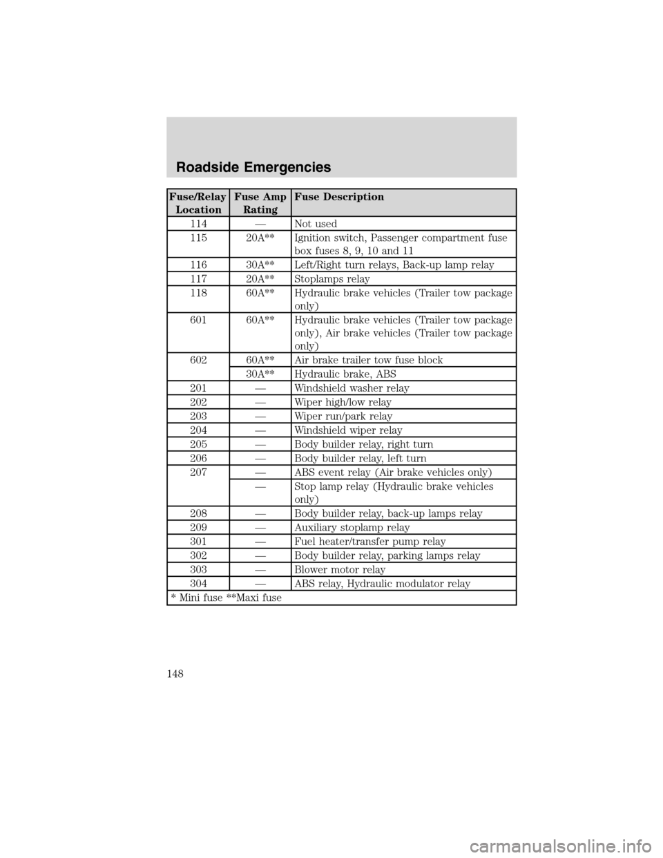
Fuse/Relay
LocationFuse Amp
RatingFuse Description
114 — Not used
115 20A** Ignition switch, Passenger compartment fuse
box fuses 8, 9, 10 and 11
116 30A** Left/Right turn relays, Back-up lamp relay
117 20A** Stoplamps relay
118 60A** Hydraulic brake vehicles (Trailer tow package
only)
601 60A** Hydraulic brake vehicles (Trailer tow package
only), Air brake vehicles (Trailer tow package
only)
602 60A** Air brake trailer tow fuse block
30A** Hydraulic brake, ABS
201 — Windshield washer relay
202 — Wiper high/low relay
203 — Wiper run/park relay
204 — Windshield wiper relay
205 — Body builder relay, right turn
206 — Body builder relay, left turn
207 — ABS event relay (Air brake vehicles only)
— Stop lamp relay (Hydraulic brake vehicles
only)
208 — Body builder relay, back-up lamps relay
209 — Auxiliary stoplamp relay
301 — Fuel heater/transfer pump relay
302 — Body builder relay, parking lamps relay
303 — Blower motor relay
304 — ABS relay, Hydraulic modulator relay
* Mini fuse **Maxi fuse
Roadside Emergencies
148
2010 F-650/750(f67)
Supplement(supplement), 1st Printing
USA(fus)
Page 152 of 274
Preparing your vehicle
1.Use only a 12–volt supply to start your vehicle.Do not attach the
jumper cables to the glow plug relay as this could severely damage the
glow plugs, injector driver module and PCM.
2. Do not disconnect the battery of the disabled vehicle as this could
damage the vehicle’s electrical system.
3. Park the booster vehicle close to the hood of the disabled vehicle making
sure the two vehiclesdo nottouch. Set the parking brake on both vehicles
and stay clear of the engine cooling fan and other moving parts.
4. Check all battery terminals and remove any excessive corrosion before
you attach the battery cables. Ensure that vent caps are tight and level.
5. Turn the heater fan on in both vehicles to protect from any electrical
surges. Turn all other accessories off.
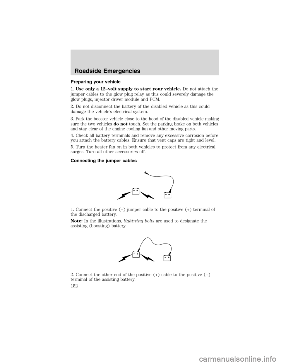
Connecting the jumper cables
1. Connect the positive (+) jumper cable to the positive (+) terminal of
the discharged battery.
Note:In the illustrations,lightning boltsare used to designate the
assisting (boosting) battery.
2. Connect the other end of the positive (+) cable to the positive (+)
terminal of the assisting battery.
+–+–
+–+–
Roadside Emergencies
152
2010 F-650/750(f67)
Supplement(supplement), 1st Printing
USA(fus)