wheel FORD F650 2011 12.G User Guide
[x] Cancel search | Manufacturer: FORD, Model Year: 2011, Model line: F650, Model: FORD F650 2011 12.GPages: 290, PDF Size: 1.96 MB
Page 22 of 290
Rear brakes
Drum:Make sure there are no cracks, dents or holes
and no loose or missing bolts. Make sure brake
linings are not worn, dangerously thin or
contaminated by lubricant.
Rear wheels
Spacers:Make sure dual wheels are evenly separated
and that tires are not touching one another.
Rims:Check for damaged or bent rims. Rims should
not have welding repairs and no rust trails that
indicate it is loose on the wheel.
Lug nuts:Make sure all lug nuts are present and not
loose (look for rust trails around the lug nuts).
There should be no cracks radiating from the
lug bolt holes or distortion of the bolt holes.
Trailer
If you are pulling a trailer, an inspection of the trailer similar to that of
the tractor should be done. Such an inspection should follow trailer
manufacturer recommendations and should include at a minimum:
general condition, landing gear, doors, sides, lights, reflectors,
suspension, brakes, tires, wheels, cargo placement, stability and
tie-downs.
Transmission
If your vehicle is equipped with an automatic transmission, regularly
check the transmission’s neutral start switch. The engine should only
start in the N (Neutral) or P (Park) positions.
WARNING:If the unit starts in gear and/or the neutral start
switch is not functioning correctly, the vehicle may inadvertently
move which could result in property damage, personal injury or death.
Check the transmission fluid level and shift linkage for proper operation.
Vehicle Inspection Guide
22
2011 F-650/750(f67)
Supplement, 2nd Printing
USA(fus)
Page 57 of 290
TILT STEERING
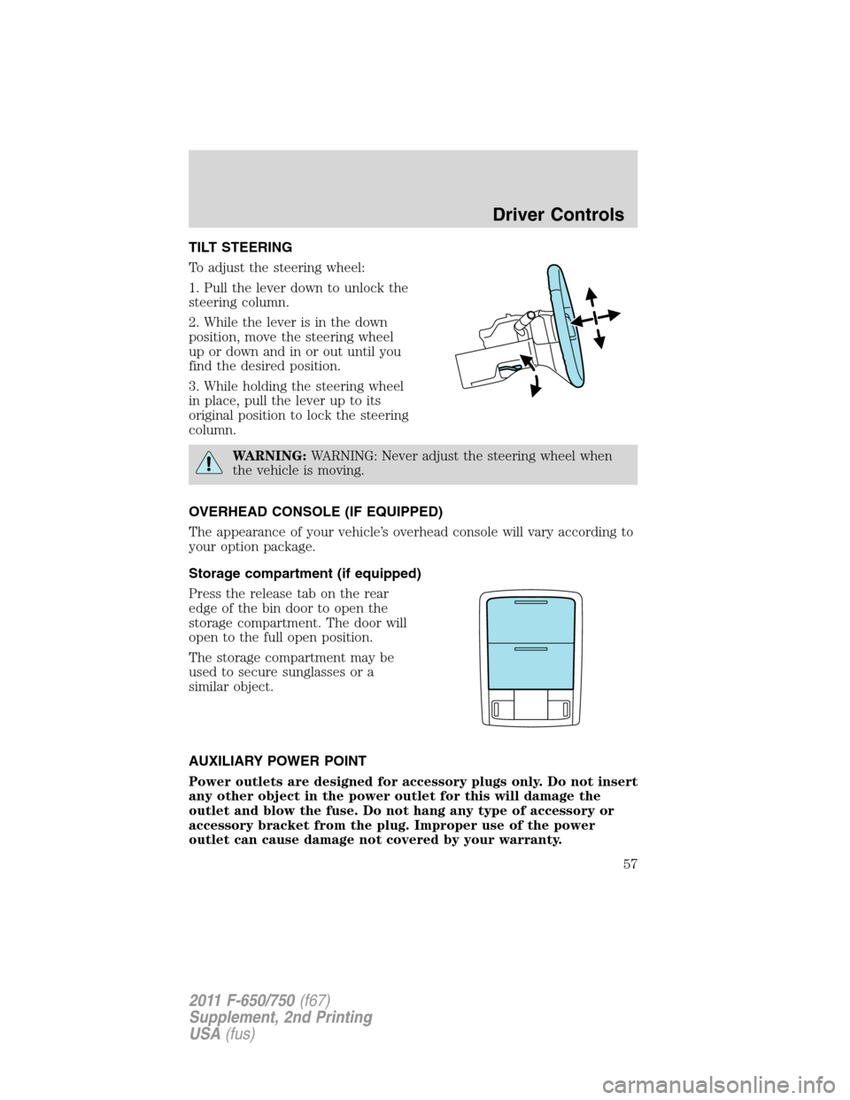
To adjust the steering wheel:
1. Pull the lever down to unlock the
steering column.
2. While the lever is in the down
position, move the steering wheel
up or down and in or out until you
find the desired position.
3. While holding the steering wheel
in place, pull the lever up to its
original position to lock the steering
column.
WARNING:WARNING: Never adjust the steering wheel when
the vehicle is moving.
OVERHEAD CONSOLE (IF EQUIPPED)
The appearance of your vehicle’s overhead console will vary according to
your option package.
Storage compartment (if equipped)
Press the release tab on the rear
edge of the bin door to open the
storage compartment. The door will
open to the full open position.
The storage compartment may be
used to secure sunglasses or a
similar object.
AUXILIARY POWER POINT
Power outlets are designed for accessory plugs only. Do not insert
any other object in the power outlet for this will damage the
outlet and blow the fuse. Do not hang any type of accessory or
accessory bracket from the plug. Improper use of the power
outlet can cause damage not covered by your warranty.
Driver Controls
57
2011 F-650/750(f67)
Supplement, 2nd Printing
USA(fus)
Page 64 of 290
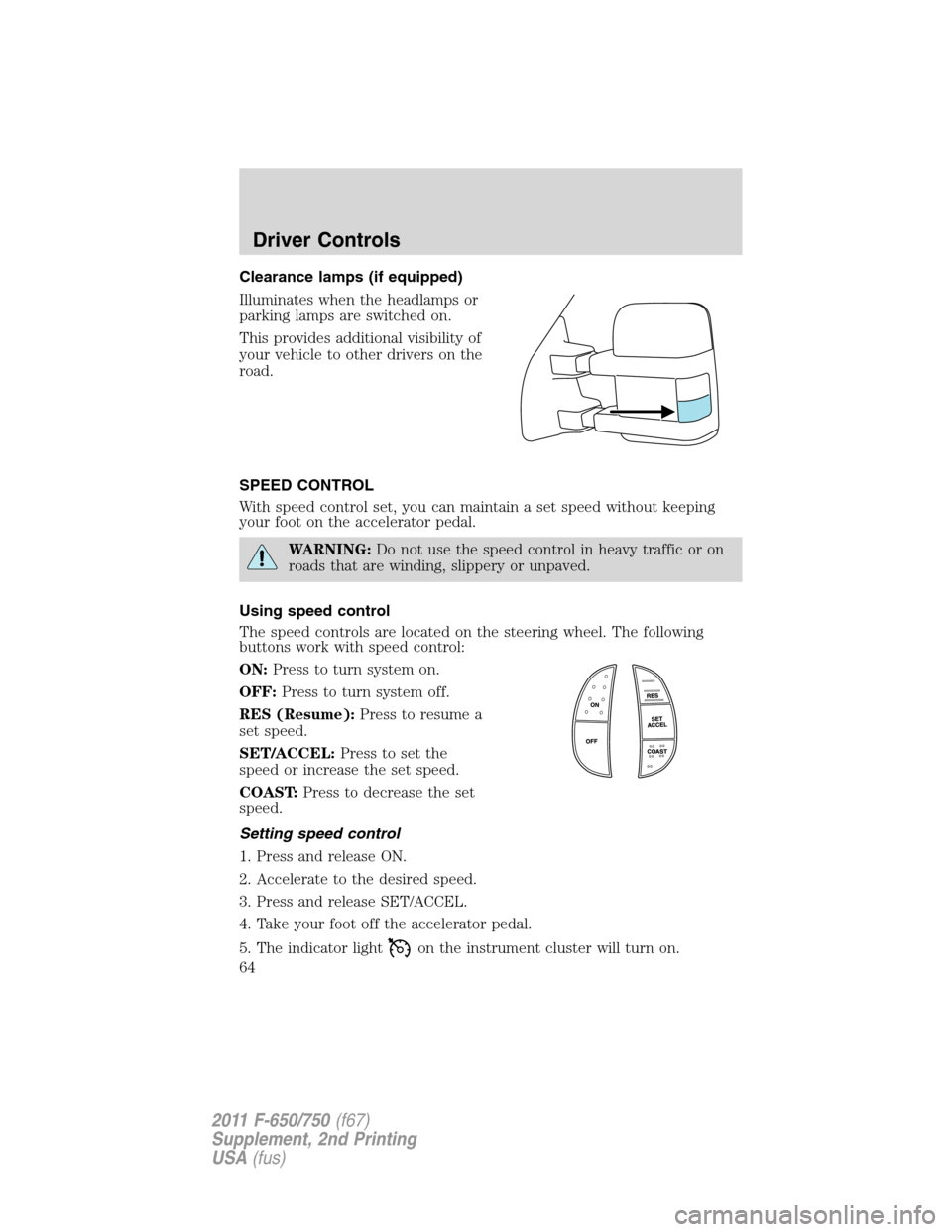
Clearance lamps (if equipped)
Illuminates when the headlamps or
parking lamps are switched on.
This provides additional visibility of
your vehicle to other drivers on the
road.
SPEED CONTROL
With speed control set, you can maintain a set speed without keeping
your foot on the accelerator pedal.
WARNING:Do not use the speed control in heavy traffic or on
roads that are winding, slippery or unpaved.
Using speed control
The speed controls are located on the steering wheel. The following
buttons work with speed control:
ON:Press to turn system on.
OFF:Press to turn system off.
RES (Resume):Press to resume a
set speed.
SET/ACCEL:Press to set the
speed or increase the set speed.
COAST:Press to decrease the set
speed.
Setting speed control
1. Press and release ON.
2. Accelerate to the desired speed.
3. Press and release SET/ACCEL.
4. Take your foot off the accelerator pedal.
5. The indicator light
on the instrument cluster will turn on.
Driver Controls
64
2011 F-650/750(f67)
Supplement, 2nd Printing
USA(fus)
Page 108 of 290
•Always shift to a lower gear at high altitudes to prevent engine
smoking.
•Operate in a gear that will permit an engine speed not in excess of the
maximum governed speed or high-idle RPM (no load).
•Normally, choose the same gear to descend the hill that you would use
to ascend the hill.
WARNING:All vehicles have blind spots. To reduce the risk of
severe injury or property damage, never move your vehicle to
the side or rear or change lanes without being sure your way is clear
on both sides and to your rear.
Backing up
WARNING:To reduce the risk of the possibility of personal
injury while backing the vehicle, always be sure your vehicle’s
path is clear.
Before backing your vehicle, be sure you can do so safely. If anything
behind the cab limits your view, do not rely on mirrors alone to ensure
that your intended path is clear. If other people are in the vicinity, have
someone standing well behind your vehicle and outside of your intended
path (visible through an exterior mirror) guide you as you back up.
Although OSHA or some governmental regulations may require the use
of an electrical or mechanical back-up alarm to warn bystanders, such an
alarm does not ensure that the intended path is clear. When in doubt,
get out of the vehicle and visually check the intended path is clear;
back-up slowly as to allow others time to move, if necessary.
If an electrical back-up alarm is installed, it should be connected to the
back-up lamp circuit.
Parking your vehicle
Always use the parking brake. When parking on a grade, block the
wheels and turn the front wheels to one side so that if the vehicle rolls,
the front tires will act against the curb to stop the vehicle. The front
wheels will be more effective at stopping a rolling vehicle than the rear
wheels.
Driving
108
2011 F-650/750(f67)
Supplement, 2nd Printing
USA(fus)
Page 112 of 290
WARNING:If the red BRAKE warning lamp in the instrument
cluster remains illuminated after engine start up, this indicates a
system failure in the Full Power Brake System. Stop the vehicle safely
as soon as possible and seek service immediately.
Note:During normal driving the pump/motors may be heard
replenishing the accumulators. This is a normal function of the Full
Power Brake System.
Parking brake
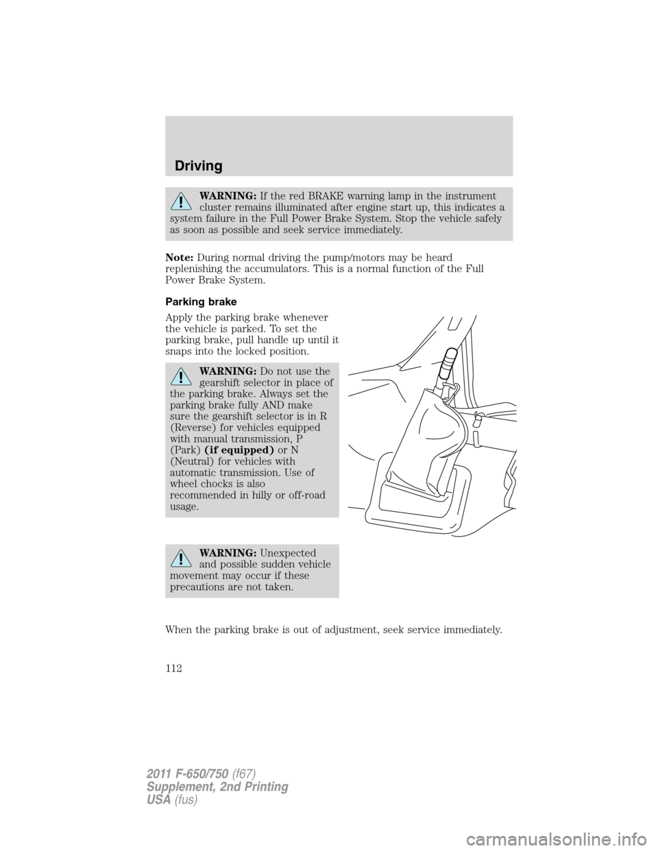
Apply the parking brake whenever
the vehicle is parked. To set the
parking brake, pull handle up until it
snaps into the locked position.
WARNING:Do not use the
gearshift selector in place of
the parking brake. Always set the
parking brake fully AND make
sure the gearshift selector is in R
(Reverse) for vehicles equipped
with manual transmission, P
(Park)(if equipped)or N
(Neutral) for vehicles with
automatic transmission. Use of
wheel chocks is also
recommended in hilly or off-road
usage.
WARNING:Unexpected
and possible sudden vehicle
movement may occur if these
precautions are not taken.
When the parking brake is out of adjustment, seek service immediately.
Driving
112
2011 F-650/750(f67)
Supplement, 2nd Printing
USA(fus)
Page 113 of 290
The parking BRAKE warning lamp
in the instrument cluster illuminates
and will remain illuminated (when
the ignition is turned on) until the
parking brake is released.
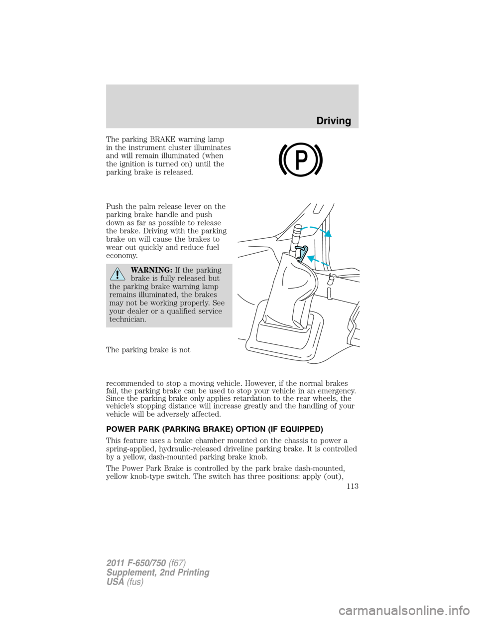
Push the palm release lever on the
parking brake handle and push
down as far as possible to release
the brake. Driving with the parking
brake on will cause the brakes to
wear out quickly and reduce fuel
economy.
WARNING:If the parking
brake is fully released but
the parking brake warning lamp
remains illuminated, the brakes
may not be working properly. See
your dealer or a qualified service
technician.
The parking brake is not
recommended to stop a moving vehicle. However, if the normal brakes
fail, the parking brake can be used to stop your vehicle in an emergency.
Since the parking brake only applies retardation to the rear wheels, the
vehicle’s stopping distance will increase greatly and the handling of your
vehicle will be adversely affected.
POWER PARK (PARKING BRAKE) OPTION (IF EQUIPPED)
This feature uses a brake chamber mounted on the chassis to power a
spring-applied, hydraulic-released driveline parking brake. It is controlled
by a yellow, dash-mounted parking brake knob.
The Power Park Brake is controlled by the park brake dash-mounted,
yellow knob-type switch. The switch has three positions: apply (out),
P
Driving
113
2011 F-650/750(f67)
Supplement, 2nd Printing
USA(fus)
Page 116 of 290
WARNING:Block the wheels to help prevent the vehicle from
moving.
WARNING:Unexpected and possibly sudden vehicle movement
may occur if these precautions are not taken.
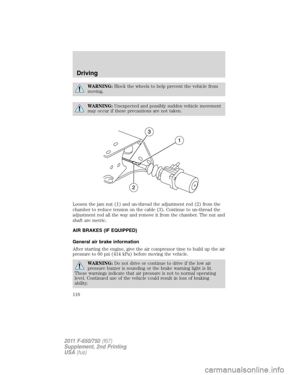
Loosen the jam nut (1) and un-thread the adjustment rod (2) from the
chamber to reduce tension on the cable (3). Continue to un-thread the
adjustment rod all the way and remove it from the chamber. The nut and
shaft are metric.
AIR BRAKES (IF EQUIPPED)
General air brake information
After starting the engine, give the air compressor time to build up the air
pressure to 60 psi (414 kPa) before moving the vehicle.
WARNING:Do not drive or continue to drive if the low air
pressure buzzer is sounding or the brake warning light is lit.
These warnings indicate that air pressure is not to normal operating
level. Continued use of the vehicle could result in loss of braking
ability.
Driving
116
2011 F-650/750(f67)
Supplement, 2nd Printing
USA(fus)
Page 119 of 290
Air brake reservoir draining
WARNING:Failure to drain air brake reservoirs can result in a
reduction or loss of braking ability due to fluid accumulation in
the reservoir and/or possible freeze-up during cold weather.
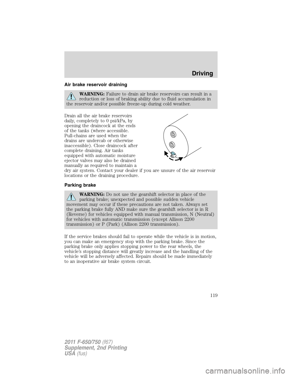
Drain all the air brake reservoirs
daily, completely to 0 psi/kPa, by
opening the draincock at the ends
of the tanks (where accessible.
Pull-chains are used when the
drains are undercab or otherwise
inaccessible). Close draincock after
complete draining. Air tanks
equipped with automatic moisture
ejector valves may also be drained
manually as required to maintain a
dry air system. Contact your dealer if you are unsure of the air reservoir
locations or the draining procedure.
Parking brake
WARNING:Do not use the gearshift selector in place of the
parking brake; unexpected and possible sudden vehicle
movement may occur if these precautions are not taken. Always set
the parking brake fully AND make sure the gearshift selector is in R
(Reverse) for vehicles equipped with manual transmission, N (Neutral)
for vehicles with automatic transmission (except Allison 2200
transmission) or P (Park) (Allison 2200 transmission).
If the service brakes should fail to operate while the vehicle is in motion,
you can make an emergency stop with the parking brake. Since the
parking brake only applies stopping power to the rear wheels, the
vehicle’s stopping distance will greatly increase and the handling of the
vehicle will be adversely affected. Repairs should be made immediately
to an inoperative air brake system circuit.
Driving
119
2011 F-650/750(f67)
Supplement, 2nd Printing
USA(fus)
Page 120 of 290
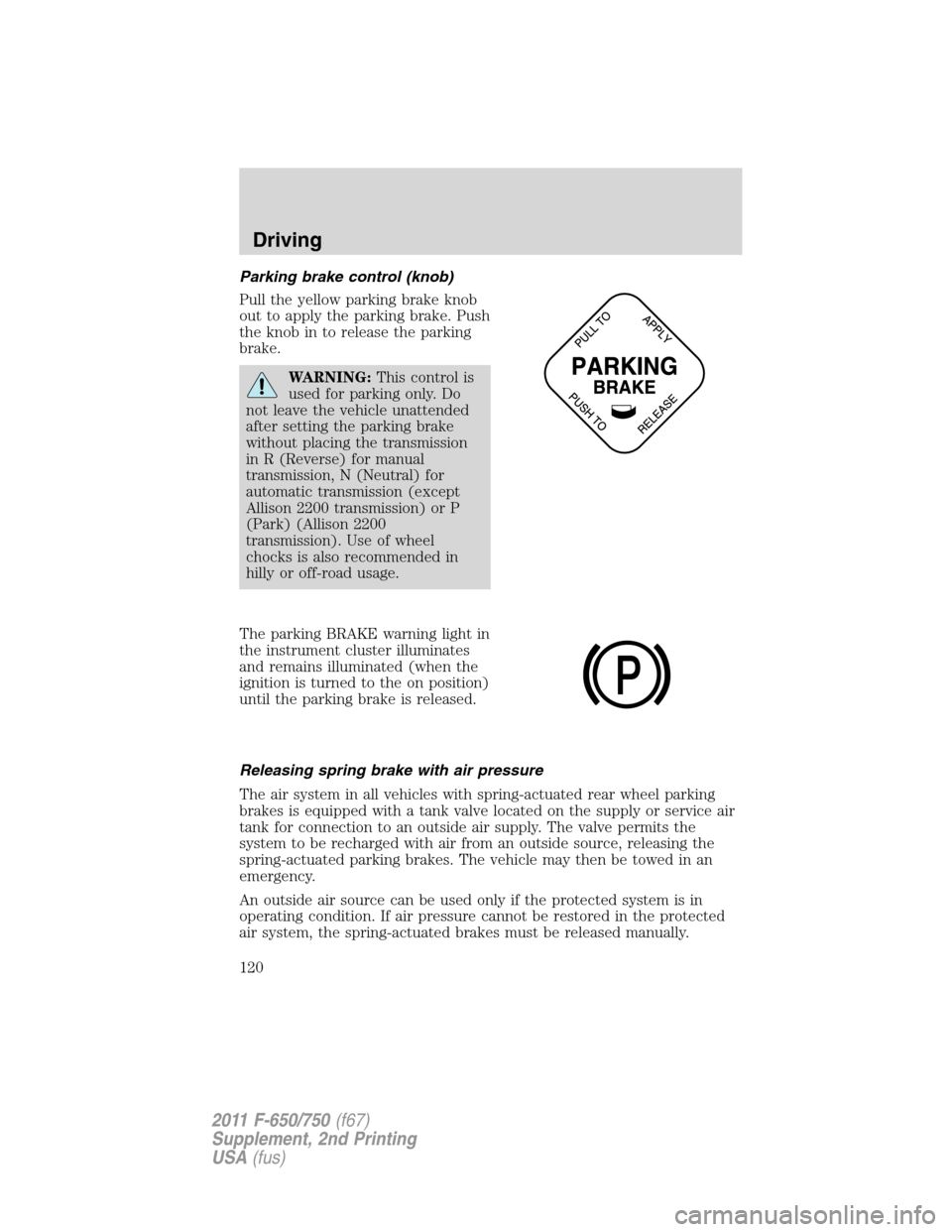
Parking brake control (knob)
Pull the yellow parking brake knob
out to apply the parking brake. Push
the knob in to release the parking
brake.
WARNING:This control is
used for parking only. Do
not leave the vehicle unattended
after setting the parking brake
without placing the transmission
in R (Reverse) for manual
transmission, N (Neutral) for
automatic transmission (except
Allison 2200 transmission) or P
(Park) (Allison 2200
transmission). Use of wheel
chocks is also recommended in
hilly or off-road usage.
The parking BRAKE warning light in
the instrument cluster illuminates
and remains illuminated (when the
ignition is turned to the on position)
until the parking brake is released.
Releasing spring brake with air pressure
The air system in all vehicles with spring-actuated rear wheel parking
brakes is equipped with a tank valve located on the supply or service air
tank for connection to an outside air supply. The valve permits the
system to be recharged with air from an outside source, releasing the
spring-actuated parking brakes. The vehicle may then be towed in an
emergency.
An outside air source can be used only if the protected system is in
operating condition. If air pressure cannot be restored in the protected
air system, the spring-actuated brakes must be released manually.
P
Driving
120
2011 F-650/750(f67)
Supplement, 2nd Printing
USA(fus)
Page 121 of 290
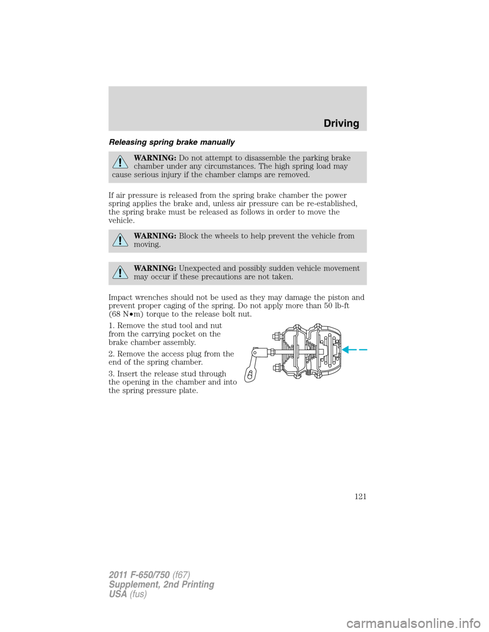
Releasing spring brake manually
WARNING:Do not attempt to disassemble the parking brake
chamber under any circumstances. The high spring load may
cause serious injury if the chamber clamps are removed.
If air pressure is released from the spring brake chamber the power
spring applies the brake and, unless air pressure can be re-established,
the spring brake must be released as follows in order to move the
vehicle.
WARNING:Block the wheels to help prevent the vehicle from
moving.
WARNING:Unexpected and possibly sudden vehicle movement
may occur if these precautions are not taken.
Impact wrenches should not be used as they may damage the piston and
prevent proper caging of the spring. Do not apply more than 50 lb-ft
(68 N•m) torque to the release bolt nut.
1. Remove the stud tool and nut
from the carrying pocket on the
brake chamber assembly.
2. Remove the access plug from the
end of the spring chamber.
3. Insert the release stud through
the opening in the chamber and into
the spring pressure plate.
Driving
121
2011 F-650/750(f67)
Supplement, 2nd Printing
USA(fus)