service schedule FORD F650 2013 12.G Owners Manual
[x] Cancel search | Manufacturer: FORD, Model Year: 2013, Model line: F650, Model: FORD F650 2013 12.GPages: 378, PDF Size: 3.82 MB
Page 12 of 378
FORD CREDIT (U.S. ONLY)
Ford Credit offers a full range of financing and lease plans to help you
acquire your vehicle. If you have financed or leased your vehicle through
Ford Credit, thank you for your business.
For your convenience, we offer a number of ways to contact us, as well
as help manage your account.
Phone: 1-800-727-7000
For more information regarding Ford Credit, as well as access to
Account Manager, please go to www.fordcredit.com.
REPLACEMENT PARTS RECOMMENDATION
Your vehicle has been built to the highest standards using quality parts.
We recommend that you demand the use of genuine Ford and Motorcraft
parts whenever your vehicle requires scheduled maintenance or repair.
You can clearly identify genuine Ford and Motorcraft parts by looking for
the Ford, FoMoCo or Motorcraft branding on the parts or their
packaging.
Scheduled Maintenance and Mechanical Repairs
One of the best ways for you to make sure that your vehicle provides
years of service is to have it maintained in line with our
recommendations using parts that conform to the specifications detailed
in this owner’s manual. Genuine Ford and Motorcraft parts meet or
exceed these specifications.
Collision Repairs
We hope that you never experience a collision, but accidents do happen.
Genuine Ford replacement collision parts meet our stringent
requirements for fit, finish, structural integrity, corrosion protection and
dent resistance. During vehicle development, we validate that these parts
deliver the intended level of protection as a whole system. A great way
to know for sure you are getting this level of protection is to use genuine
Ford replacement collision parts.
Warranty on Replacement Parts
Genuine Ford and Motorcraft replacement parts are the only
replacement parts that benefit from a Ford Warranty. Damage caused to
your vehicle as a result of the failure of non-Ford parts may not be
covered by the Ford Warranty. For additional information, see the terms
and conditions of the Ford Warranty.
Introduction11
2013 F-650/750(f67)
Owners Guide gf, 2nd Printing, March 2013
USA(fus)
Page 151 of 378
Air Chamber Stroke Indication
Air chamber push rods have orange stroke indicator markers that warn
when the braking system requires adjustment or repair. The orange
stripe is painted on the air chamber push rod at the slack adjuster stroke
dimension which requires service when visible during brake application.
Air brake inspection and adjustment or repairs should be performed by a
qualified service technician in accordance with the instructions in the
service manual.
Cam Brakes - Automatic Slack Adjusters
WARNING:Do not manually adjust the automatic slack adjusters
to correct excessive push rod stroke as it may result in reduced
brake effectiveness and a vehicle crash. Excessive push rod stroke
indicates that a problem exists with the automatic adjuster, with the
installation of the adjuster, or with foundation brake components that
manual adjustment does not remedy. Seek service from a qualified
facility for excessive push rod stroke.
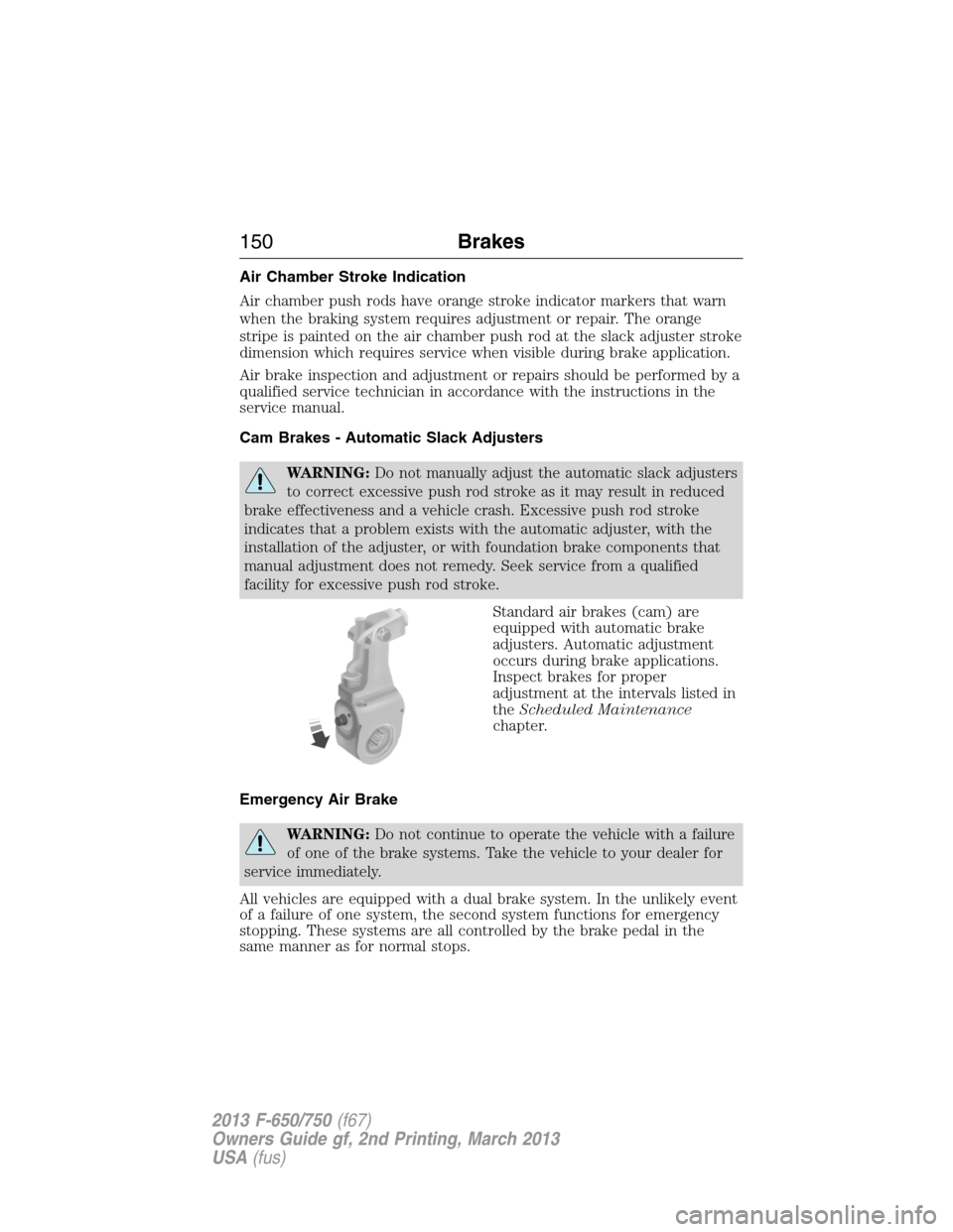
Standard air brakes (cam) are
equipped with automatic brake
adjusters. Automatic adjustment
occurs during brake applications.
Inspect brakes for proper
adjustment at the intervals listed in
theScheduled Maintenance
chapter.
Emergency Air Brake
WARNING:Do not continue to operate the vehicle with a failure
of one of the brake systems. Take the vehicle to your dealer for
service immediately.
All vehicles are equipped with a dual brake system. In the unlikely event
of a failure of one system, the second system functions for emergency
stopping. These systems are all controlled by the brake pedal in the
same manner as for normal stops.
150Brakes
2013 F-650/750(f67)
Owners Guide gf, 2nd Printing, March 2013
USA(fus)
Page 177 of 378
*Specific GCWR and maximum trailer weight applicable to a given
F–650/750 model is dependent on many variables including transmission
capability. Check with your sales consultant for the exact rating on your
vehicle.
ESSENTIAL TOWING CHECKS
Service your vehicle more frequently if you tow a trailer. See your
scheduled maintenance information.
For load specification terms found on the Tire Label and Safety
Compliance Certification Label and for instructions on calculating your
vehicle’s load, seeLoad limitin theLoad Carryingchapter.
Hitches
Do not use a hitch that either clamps onto the bumper or attaches to the
axle.
Distribute the trailer load so 10-15% of the total trailer weight is on the
tongue.
Safety Chains
Note:Do not attach safety chains to the bumper.
Always connect the trailer’s safety chains to the frame or hook retainers
of your vehicle hitch.
To connect the trailer’s safety chains, cross the chains under the trailer
tongue and allow enough slack for turning tight corners. Do not allow the
chains to drag on the ground.
Trailer Brakes
WARNING:Do not connect a trailer’s hydraulic brake system
directly to your vehicle’s brake system. Your vehicle may not have
enough braking power and your chances of having a crash greatly
increase.
Electric brakes and manual, automatic or surge-type trailer brakes are
safe if installed properly and adjusted to the manufacturer’s
specifications. The trailer brakes must meet local and federal regulations.
The braking system of the tow vehicle is rated for operation at
the GVWR not GCWR.
176Towing
2013 F-650/750(f67)
Owners Guide gf, 2nd Printing, March 2013
USA(fus)
Page 190 of 378
GETTING THE SERVICES YOU NEED
Warranty repairs to your vehicle must be performed by an authorized
Ford dealer. While any authorized dealer handling your vehicle line will
provide warranty service, we recommend that you return to your
authorized selling dealer to ensure your continued satisfaction.
Please note that certain warranty repairs require special training or
equipment, so not all authorized dealers are authorized to perform all
warranty repairs. This means that, depending on the warranty repair
needed, you may need to take your vehicle to another authorized dealer.
If you have questions or concerns, or are unsatisfied with the service you
are receiving, follow these steps:
1. Contact your Sales Representative or Service Advisor at your selling
or servicing dealership.
2. If your inquiry or concern remains unresolved, contact the Sales
Manager or Service Manager at the dealership.
3. If the inquiry or concern cannot be resolved at the dealership level,
contact the Ford Commercial Vehicle Operations Hotline. Please have
the following information available:
•Vehicle Identification Number (VIN)
•your telephone number (home and business)
•the name of the authorized dealer and city where located
•the vehicle’s current odometer reading.
In some states, you must directly notify Ford in writing before pursuing
remedies under your state’s warranty laws. Ford is also allowed a final
repair attempt in some states.
In the United States:
Mailing address
Ford Motor Company
Commercial Vehicle Operations
PO Box 6248
Dearborn, MI 48121
Telephone
800-782-8627 (option #3)
(TDD for the hearing impaired: 1-800-232-5952)
Online
Additional information and resources are available online at
www.fleet.ford.com:
•U.S. dealer locator by Dealer Name, City/State, or Zip Code
•Owner Guides
•Maintenance Schedules
Customer Assistance189
2013 F-650/750(f67)
Owners Guide gf, 2nd Printing, March 2013
USA(fus)
Page 206 of 378
WARNING:The use of inferior parts can adversely affect the
quality and reliability of your vehicle which, in turn, can result in
property damage, personal injury or death.
To avoid damage to the vehicle’s electrical components prior to electric
welding:
•disconnect both battery cables.
•attach the welder ground cable as close as possible to the part being
welded.
•it is recommended that the component be temporarily removed if
welding close to an electrical component.
Follow the checks and services in theScheduled Maintenancechapter.
Have your dealer or service center inspect your vehicle at least once a
year. Remember that regular maintenance and inspections usually
prevent serious problems from developing later.
If the owner or operator of the vehicle is a skilled technician and intends
on performing the vehicle maintenance and service, he is strongly urged
to purchase a service manual.
Electrical System
Periodically inspect electrical connectors on the outside of the cab and
on the engine and frame for corrosion and tightness. Exposed terminals,
such as the fuel sender, cranking motor, alternator and feed-through
studs, should be cleaned and re-coated with a lubricant sealing grease
such as Motorcraft® Silicone Brake Caliper Grease and Dielectic
Compound XG-3, or equivalent. This should include the ground cable
connector for batteries, engine and cab as well as the jump starting stud.
Accessory Feed Connections
Vehicle electrical systems are complex and often include powertrain
components, such as engine and transmission controls, instrument
panels, ABS, etc. While most systems operate on battery voltage
(12 volts), some systems can be as high as 90 volts or as low as five
volts. See theElectrical Circuit Diagram Manuals,available from your
vehicle’s manufacturer, to make sure that any additional body lights and
accessories are connected to circuits that are both appropriate and not
overloaded. No modification should be made to any vehicle control
system without first contacting your dealer.
Maintenance205
2013 F-650/750(f67)
Owners Guide gf, 2nd Printing, March 2013
USA(fus)
Page 207 of 378
Climate Control System
Have the air conditioning system checked each spring. The refrigerant
charge, cleanliness of the condenser-evaporator cores and belt condition
are essential to system performance.
When the air conditioning system is being used daily, remove the fresh
air filter (if equipped) once each season and check for dirt, lint, etc.
Replace the filter if necessary. Vehicles operating in unusually dusty
conditions may require more frequent filter inspection and replacement.
Front Axle
Maintaining the front axle alignment to specifications is very important
and should only be performed by a qualified technician. Regular
inspections should include:
•toe-in inspection and adjustment (if necessary), particularly with
radial tires.
•checking for proper tightness of axle mounting U-bolt nuts, attaching
or mounting bolts and nuts.
•checking the axle for damage, binding, worn parts and adequate
lubrication..
•checking the kingpins for excessive wear. This should also be done
during other scheduled maintenance (tire rotation or service, wheel
bearing service, alignment, etc.). See the workshop manual for proper
procedures.
Toe-in
It is essential that correct toe-in and tire pressure be maintained for
optimum tire wear.
Inspecting steer axle tires in the first 3000–10000 service miles
(5000–16000 service kilometers) generally shows if tires are wearing
normally.
Rapid outside shoulder wear on both tires indicates too much toe-in.
Rapid inside shoulder wear on both tires indicates too much toe-out.
In P&D-type service, left-to-right steer tire tread life differentials up to
40% can be observed depending on routes and other variables.
Follow the tire manufacturer’s recommended cold inflation pressure for
the tire size, load range (ply rating) and steer axle loading typical for
their operation (each steer axle tire equals
1�2steer axle loading).
206Maintenance
2013 F-650/750(f67)
Owners Guide gf, 2nd Printing, March 2013
USA(fus)
Page 210 of 378
Air Brakes
WARNING:Do not manually adjust the automatic slack adjusters
to correct excessive push rod stroke as it may result in reduced
brake effectiveness and a vehicle crash. Excessive push rod stroke
indicates that a problem exists with the automatic adjuster, with the
installation of the adjuster, or with foundation brake components that
manual adjustment does not remedy. Seek service from a qualified
facility for excessive push rod stroke.
Inspection and adjustment:Establish a regular schedule for periodic
cleaning, lubrication and adjustment inspection based on vehicle use.
Exact maintenance intervals are difficult to predetermine since vehicles
are used in a wide variety of applications and conditions. If you are
uncertain of the proper schedule for your vehicle, contact your dealer.
Regular inspections should include:
•periodic checking (every service interval) of push rod travel or brake
adjustment. This is essential for effective braking. Brake chamber
push rods on original equipment chambers now incorporate an orange
paint marker near the base of the push rod as a stroke indicator to
aid in adjustment checks. If the push rod is clean and the brakes are
out of adjustment, the orange marker can be seen protruding from
the chamber when the brakes are applied.
•checking the brake lining (every service interval). When brake lining
or blocks are worn to within 1/16th inch (1.6 millimeters) of rivets,
replace the brake linings. This inspection or adjustment should only
be performed by a qualified technician and must be in accordance
with instructions provided by the service manual.
Do not back off or disconnect the front brakes so that they are less
effective, letting the rear brakes do all the stopping of the vehicle. Do
not overlook the brakes on the trailer either. Brake condition on the
trailer is just as important as the tractor. Proper brake balance on trucks
and tractor-trailers is essential for effective braking.
Once a year, the entire brake system must be inspected:
•Rubber components for deterioration. These components should be
inspected by a qualified technician and replaced as necessary.
Replacement intervals vary according to the severity and length of
vehicle service.
•Condition of brake drums, brake chambers and slack adjusters.
•System for air leaks.
•Hose or pipes for rust, damage and deterioration.
•Operation of service and parking brakes.
Maintenance209
2013 F-650/750(f67)
Owners Guide gf, 2nd Printing, March 2013
USA(fus)
Page 211 of 378
Some parts such as air brake chamber diaphragm, air compressor and air
cleaner should be inspected periodically and replaced if considered
unserviceable.
Air dryer:Climactic conditions affect performance of desiccant or
after-cooler type air dryers. Maintenance schedules must be established
for each specific operation.
The use of an air dryer on a vehicle does not eliminate the need to
periodically drain the air reservoirs.
Desiccant air dryer:Inspect for moisture in the air system by opening
reservoirs, draincocks or valves and checking for presence of water. The
presence of small amounts of water due to condensation is normal and
should not be considered as an indication that the dryer is not
functioning properly.
The desiccant cartridge should be replaced or rebuilt when it has been
determined that the desiccant is contaminated and does not have
adequate water absorption capacity. The desiccant change interval may
vary. It is generally recommended that the desiccant be replaced every
12 months (yearly). If experience has shown that extended or shortened
life has resulted for a particular installation, then the yearly interval can
be increased or decreased accordingly.
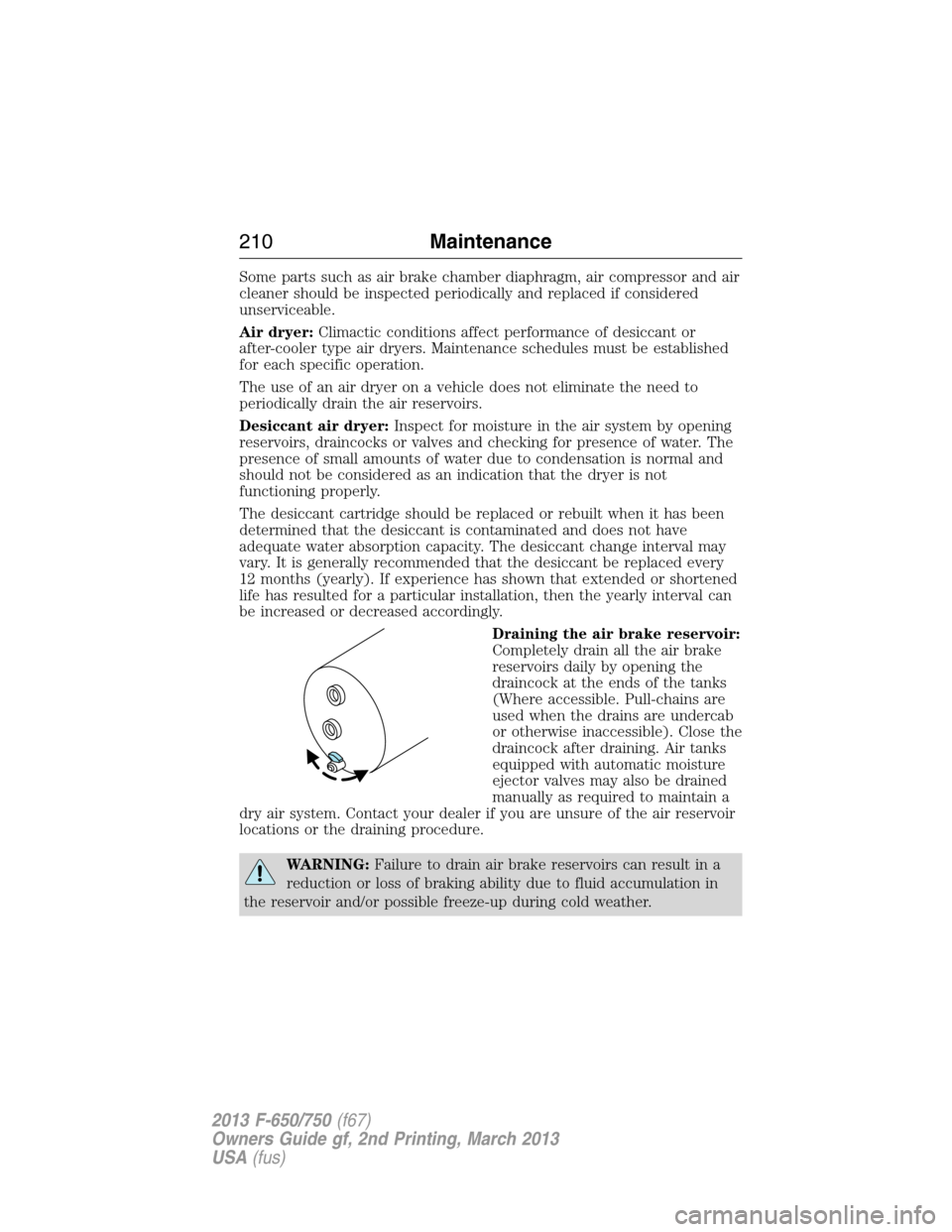
Draining the air brake reservoir:
Completely drain all the air brake
reservoirs daily by opening the
draincock at the ends of the tanks
(Where accessible. Pull-chains are
used when the drains are undercab
or otherwise inaccessible). Close the
draincock after draining. Air tanks
equipped with automatic moisture
ejector valves may also be drained
manually as required to maintain a
dry air system. Contact your dealer if you are unsure of the air reservoir
locations or the draining procedure.
WARNING:Failure to drain air brake reservoirs can result in a
reduction or loss of braking ability due to fluid accumulation in
the reservoir and/or possible freeze-up during cold weather.
210Maintenance
2013 F-650/750(f67)
Owners Guide gf, 2nd Printing, March 2013
USA(fus)
Page 212 of 378
Hydraulic Brakes
Establish a regular schedule for periodic cleaning, lubrication and
adjustment inspection based on vehicle use. Exact maintenance intervals
are difficult to predetermine since vehicles are used in a wide variety of
applications and conditions. If you are uncertain of the proper schedule
for your vehicle, contact your dealer.
Regular inspections should include:
•checking the brake lining (every service interval). Establish
inspection intervals that provide for lining replacement before damage
to the disc occurs. Excessive lining wear may expose the backing
plate to the disc causing scoring of the disc faces. This inspection
should be performed by a qualified technician and must be in
accordance with instructions provided by the service manual.
Hydraulic brake systems are power-assisted. Braking capabilities are
greatly reduced without engine assist.
•proper fluid level. The level should be at the bottom edge of the ring
on each reservoir fill port. Do not fill the master cylinder to the top of
the reservoir. If fluid level requires attention to maintain a proper
master cylinder level, this is an indication of either severe operation
(pad wear) or fluid leakage. A more frequent and thorough brake
inspection is required.
•brake lines, hoses and fittings. Repair or replace brake line tubes,
hoses or fittings as required. Inspect these components every
4000 miles (6000 kilometers):
•Lines for kinks, dents, corrosion or rupture.
•Hoses for abrasions, kinks, soft spots or rupture, collapse, cracks,
twists or loose frame supports. When replacing a hose, be sure
there is adequate clearance to the hose to avoid an abrasion to the
new hose.
•All connections for leaks.
Driveline Parking Brake
WARNING:Use wheel chocks and exercise caution when
inspecting under the vehicle. A vehicle roll-away could result in
property damage, personal injury or death.
Parking brake adjustment should only be performed by a qualified
technician, and in accordance with the instructions in the service
manual.
Maintenance211
2013 F-650/750(f67)
Owners Guide gf, 2nd Printing, March 2013
USA(fus)
Page 214 of 378
Catalytic Converter (Diesel Engine)
Note:If your vehicle is equipped with a catalytic converter/muffler,do
notblend waste oil with diesel fuel. Operate only on ultra low sulfur
(less than 15 parts per million sulfur) diesel fuel with a cetane value of
45 or higher.
If your diesel engine is equipped with a catalytic converter, it is
important to review the maintenance schedule to make sure proper
functioning of the catalytic converter. Also, take precautions not to
damage the catalytic converter when servicing your engine or storing
your vehicle.
Diesel Exhaust Fluid (DEF), Diesel Particulate Filter (DPF) and
Select Catalyst Reduction (SCR) System
See your engine operator’s manual for information regarding DEF, DPF
and SCR system service.
Air Induction System
WARNING:When performing maintenance to any turbocharged
engine with engine air inlet piping disconnected, keep loose
clothing, jewelry and long hair away from the engine air inlet piping.
A turbocharger compressor air inlet protective shield should be
installed over the turbocharger air inlet to reduce the risk of personal
injury or death.
Perform a complete inspection of the air induction system annually.
In areas where road salt is used, disassemble the joints of each aluminum
component and inspect for salt build-up and presence of chlorine that
can cause aluminum particles to flake off and enter the engine
combustion chambers. If evidence of corrosion is found (usually at the
pipe connections), use a wire brush to clean the inside of the pipes and
inside the rubber hoses.
If the intake pipes are pitted at the joint ends, use Motorcraft® Silicone
Gasket and Sealant TA-30 to seal the joints. Make sure no excess
material is on the inside of the pipes that can be pulled into the engine.
If the service condition of the pipes, hoses or clamps is questionable,
replace the defective part(s).
Make sure all dust and debris has been cleaned out of the pipes and
couplings with a clean, damp rag prior to reassembly.
Maintenance213
2013 F-650/750(f67)
Owners Guide gf, 2nd Printing, March 2013
USA(fus)