transmission oil FORD F650 2013 12.G Owners Manual
[x] Cancel search | Manufacturer: FORD, Model Year: 2013, Model line: F650, Model: FORD F650 2013 12.GPages: 378, PDF Size: 3.82 MB
Page 5 of 378
Roadside Emergencies 184
Getting roadside assistance..............................184
Hazard flasher control..................................185
Jump-starting the vehicle...............................185
Customer Assistance 189
Getting assistance outside the U.S. and Canada...............191
Reporting safety defects (U.S. only).......................193
Reporting safety defects (Canada only).....................193
Fuses 194
Changing a fuse......................................194
Fuse specification chart................................195
Fuses and relays......................................203
Maintenance 204
General information...................................204
Opening and closing the hood............................215
Engine oil dipstick....................................217
Engine oil check......................................218
Engine coolant check..................................219
Automatic transmission fluid check........................223
Brake fluid check.....................................229
Power steering fluid check..............................231
Fuel filter...........................................232
Washer fluid check....................................232
Changing the vehicle battery.............................233
Checking the wiper blades..............................235
Changing the wiper blades..............................236
Air filter(s).........................................236
Adjusting the headlamps................................239
Changing a bulb......................................239
Bulb specification chart.................................241
4Table of Contents
2013 F-650/750(f67)
Owners Guide gf, 2nd Printing, March 2013
USA(fus)
Page 17 of 378
Engine Starting (Parking Brake Applied)
Safety and
Emergency
Equipment•Before entering the cab, verify that the vehicle
is equipped with spare electrical fuses (if used),
three red reflective triangles, a properly charged
and rated fire extinguisher and wheel chocks.
•Walk around the vehicle and verify all steps
and grab handles, inside and out (as well as
behind), are tight and clean. Use extreme caution
and a three-point stance at all times.
•Inspect door latches for proper closing,
latching and locking.
Starting the
EngineSet the parking brake. If starting a vehicle with a
manual transmission, press the clutch and verify
the transmission is in neutral. If starting a vehicle
with an automatic transmission, make sure the
gearshift lever is in positionNorP(if equipped
with a park position).
Diesel engine:Turn the key to the on position.
Turn the key to start when the wait to start
indicator light in the instrument cluster turns off.
Gasoline engine:Turn the key to start, then
release it as soon as the engine starts.
Engine Oil
PressureVerify pressure builds to normal operating range.
Air Chime (If
Equipped with an
Air Compressor)The low air pressure warning chime should sound
immediately after the engine starts but before the
compressor has built-up pressure. The chime
should stop when the air pressure reaches 70 psi
(483 kPa) (or more). Let the air pressure build
to governed cut-out pressure, which should occur
between 115–130 psi (793–896 kPa).
AcceleratorPress the accelerator and verify that it operates
smoothly, without any binding or irregular feel.
Release the pedal and verify the engine returns
to idle speed immediately.
16Vehicle Inspection Guide
2013 F-650/750(f67)
Owners Guide gf, 2nd Printing, March 2013
USA(fus)
Page 67 of 378
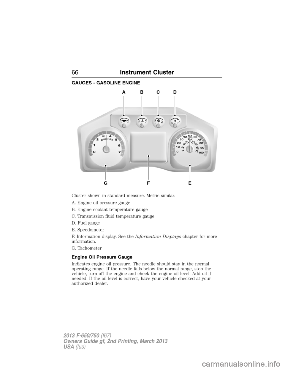
GAUGES - GASOLINE ENGINE
Cluster shown in standard measure. Metric similar.
A. Engine oil pressure gauge
B. Engine coolant temperature gauge
C. Transmission fluid temperature gauge
D. Fuel gauge
E. Speedometer
F. Information display. See theInformation Displayschapter for more
information.
G. Tachometer
Engine Oil Pressure Gauge
Indicates engine oil pressure. The needle should stay in the normal
operating range. If the needle falls below the normal range, stop the
vehicle, turn off the engine and check the engine oil level. Add oil if
needed. If the oil level is correct, have your vehicle checked at your
authorized dealer.
ABCD
GFE
66Instrument Cluster
2013 F-650/750(f67)
Owners Guide gf, 2nd Printing, March 2013
USA(fus)
Page 71 of 378
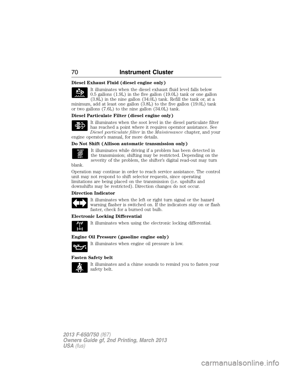
Diesel Exhaust Fluid (diesel engine only)
It illuminates when the diesel exhaust fluid level falls below
0.5 gallons (1.9L) in the five gallon (19.0L) tank or one gallon
(3.8L) in the nine gallon (34.0L) tank. Refill the tank or, at a
minimum, add at least one gallon (3.8L) to the five gallon (19.0L) tank
or two gallons (7.6L) to the nine gallon (34.0L) tank.
Diesel Particulate Filter (diesel engine only)
It illuminates when the soot level in the diesel particulate filter
has reached a point where it requires operator assistance. See
Diesel particulate filterin theMaintenancechapter, and your
engine operator’s manual, for more details.
Do Not Shift (Allison automatic transmission only)
It illuminates while driving if a problem has been detected in
the transmission; shifting may be restricted. Depending on the
severity of the problem, the shifter’s digital read-out may turn
blank.
Operation may continue in order to reach service assistance. The control
unit may not respond to shift selector requests, since operating
limitations are being placed on the transmission (i.e. upshifts and
downshifts may be restricted). Direction changes do not occur.
Direction Indicator
It illuminates when the left or right turn signal or the hazard
warning flasher is switched on. If the indicators stay on or flash
faster, check for a burned out bulb.
Electronic Locking Differential
It illuminates when using the electronic locking differential.
Engine Oil Pressure (gasoline engine only)
It illuminates when engine oil pressure is low.
Fasten Safety belt
It illuminates and a chime sounds to remind you to fasten your
safety belt.
70Instrument Cluster
2013 F-650/750(f67)
Owners Guide gf, 2nd Printing, March 2013
USA(fus)
Page 107 of 378
Note:Do not increase engine speed until the oil pressure gauge
indicates normal pressure. This should be indicated on the gauge within
15 seconds after starting.
Note:Idle the engine for three to five minutes before operating with a
full load.
Note:Try to limit engine idle to 10 minutes. Excessive idling reduces
fuel economy.
Vehicles with a Manual Transmission
Note:Do not touch the accelerator pedal.
1. Fully press the clutch pedal.
2. Start the engine.
Vehicles with an Automatic Transmission
Note:Do not touch the accelerator pedal.
1. Select positionN,orP(if equipped with a Park position).
2. Fully press the brake pedal.
3. Start the engine.
Starting the Engine with the Vehicle on a Steep Grade
When starting a diesel engine when the loaded vehicle is on a grade, the
engine RPM starts to fall slightly when the clutch is engaged. Do not
disengage the clutch and try to increase engine RPM as this may damage
driveline components. The engine recovers as the vehicle begins moving.
DIESEL PARTICULATE FILTER (DPF)
WARNING:The normal operating temperature of the exhaust
system is very high. Never work around, or attempt to repair, any
part of the exhaust system until it has cooled. Use special care when
working around the diesel particulate filter. The DPF heats up to a high
temperature after only a short period of engine operation, and can
remain hot even after the engine is turned off. Failure to follow these
instructions may result in serious personal injury.
Your vehicle is equipped with a diesel particulate filter (DPF), as part of
the after-treatment exhaust system, to trap soot and other large particles
produced by the engine combustion process. The soot that accumulates
in the filter must be periodically reduced to ash to prevent excessive
exhaust restriction. The soot reduction process, also known as “filter
regeneration,” is generally performed automatically by your engine and
after-treatment system.
106Starting and Stopping the Engine
2013 F-650/750(f67)
Owners Guide gf, 2nd Printing, March 2013
USA(fus)
Page 132 of 378
Cooling System:
•Inspect the fan for blade damage. If damage is found, replace with
the recommended parts. Inspect for fan-to-shroud interference and
any damage to shroud, such as cracks and holes.
•Do not change fan ratio or alter fan spacer dimensions and positions.
•Inspect fan clutch for proper operation. Make sure the fan is
disengaged when cooling of the engine is not required.
•Inspect radiator shutters (if equipped) for proper operation. The
shutters should be open during normal operating temperatures.
Engine:Valve covers and block covers are made to damp-out engine
mechanical noise and, if needed, should be replaced with recommended
parts. Check for mechanical isolations.
Transmission Enclosure:Inspect for cracks, holes and tears. Clean any
deposits, such as oil, dirt and stones.
Exhaust System:
•Inspect for leaks at various joint connections and loose clamps.
•Perform a visual inspection for cracks or holes in the muffler and tail
pipe.
•Always use the recommended parts when items need to be replaced.
•Do not change the tail pipe elbow or offset tail pipe orientation from
the standard position as originally received.
•To avoid abnormal changes in vehicle sound levels, it is necessary for
the owner to perform inspections and necessary maintenance at the
intervals shown in theScheduled Maintenancechapter.
Fuel and Refueling131
2013 F-650/750(f67)
Owners Guide gf, 2nd Printing, March 2013
USA(fus)
Page 170 of 378
Parking
WARNING:When parking your vehicle, do not leave the
transmission in gear; if the key is in the on position and the
vehicle rolls, the engine could start. Failure to follow these instructions
could result in an unattended vehicle moving, possibly causing personal
injury or property damage.
Always use the parking brake. When parking on a grade, block the
wheels and turn the front wheels to one side so that if the vehicle rolls,
the front tires act against the curb to stop the vehicle. The front wheels
are more effective at stopping a rolling vehicle than the rear wheels.
Cold Weather
Note:Idling in cold weather does not heat the engine to its normal
operating temperature. Long periods of idling in cold weather can cause
a build-up of heavy deposits of carbon and rust on valve stems causing
them to stick which, in turn, can cause valvetrain damage.
Note:The use of winter fronts, or other air-restrictive devices mounted
in front of the radiator on vehicles with chassis-mounted charge air
coolers, are not recommended unless extremely cold weather conditions
exist. Airflow restriction can cause high exhaust temperatures, power
loss, excessive fan usage and a reduction in fuel economy. If you must
use a winter front, the device should have a permanent opening of at
least 120 square inches (774 square centimeters) directly in line with the
fan hub.
For best engine operation in temperatures of 32°F (0°C) or lower:
•Make sure the batteries are the correct type and are fully charged.
Check other electrical components to make sure they are in optimum
condition.
•Use a permanent-type engine coolant to protect the engine against
damage from freezing.
•If your vehicle is equipped with a water-fuel separator, drain it daily.
Fill the fuel tank at the end of daily operation to prevent
condensation in the fuel system.
•Use the proper engine oil and maintain it at its proper level.
•At temperatures of –4°F (–20°C) or below, it is recommended that
you use a crankcase-mounted coolant heater to improve cold engine
starting.
•If operating in arctic temperatures of –20°F (–29°C) or lower, consult
your truck dealer for information about special cold weather
equipment and precautions.
Driving Aids169
2013 F-650/750(f67)
Owners Guide gf, 2nd Printing, March 2013
USA(fus)
Page 201 of 378
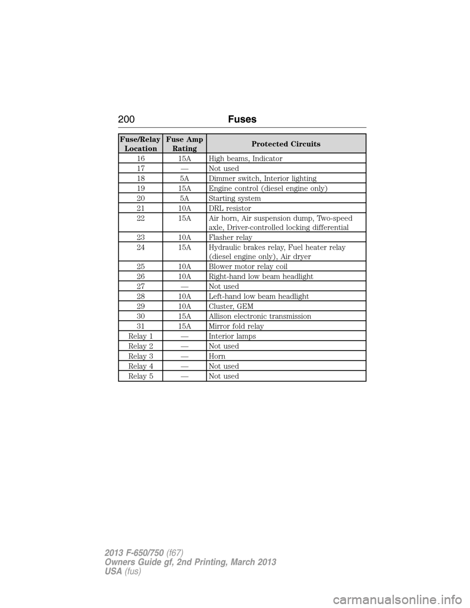
Fuse/Relay
LocationFuse Amp
RatingProtected Circuits
16 15A High beams, Indicator
17 — Not used
18 5A Dimmer switch, Interior lighting
19 15A Engine control (diesel engine only)
20 5A Starting system
21 10A DRL resistor
22 15A Air horn, Air suspension dump, Two-speed
axle, Driver-controlled locking differential
23 10A Flasher relay
24 15A Hydraulic brakes relay, Fuel heater relay
(diesel engine only), Air dryer
25 10A Blower motor relay coil
26 10A Right-hand low beam headlight
27 — Not used
28 10A Left-hand low beam headlight
29 10A Cluster, GEM
30 15A Allison electronic transmission
31 15A Mirror fold relay
Relay 1 — Interior lamps
Relay 2 — Not used
Relay 3 — Horn
Relay 4 — Not used
Relay 5 — Not used
200Fuses
2013 F-650/750(f67)
Owners Guide gf, 2nd Printing, March 2013
USA(fus)
Page 215 of 378
Chassis-mounted Charge Air Cooler
Visually inspect the core assembly for debris and clogging of external fins
with the engine off. Prior to engine operation, remove any debris
blocking the core.
•Turbocharger-to-charge air cooler
•Charge air cooler-to-intake manifold pipe
•Mounting bracket
•Chassis-mounted charge air cooler core
Inspect air intake piping:
•Check for accumulation of salt deposits (where applicable).
If present, disassemble and clean the complete air intake piping
system. If the intake piping is pitted, use Motorcraft® Silicone Gasket
and Sealant TA-30 to seal joints against leakage.
•Check for loose hoses and clamps.
•Check for ruptured or collapsed hoses.
•Check air cleaner housing for cracks.
Suspension Inspection
Note:Do not adjust air suspension height to any setting other than the
specified setting. Altering the height setting changes the driveline angle
and may result in unwarrantable component damage, such as
transmission component damage.
Verify drive axle air suspension height and height control valve
performance at engine oil change intervals.
Periodically check:
•Condition of spring leaves for evidence of fatigue, bending or
breakage.
•Condition of suspension mounting brackets and bushings.
•Torque rod mounting fasteners for tightness.
•For proper suspension alignment. This must be maintained at all
times.
•U-bolts. After the chassis has been operating under load for
1000 miles (1600 kilometers) or six months (whichever comes first),
the U-bolt nuts must be re-torqued. The U-bolt nuts must be
re-torqued every 36000 miles (60000 kilometers) thereafter. The
U-bolt and nut threads and seats should be cleaned and lubricated to
make sure a like new condition when re-torquing.
Note:SeeSpring U-bolt checklater in this chapter.
214Maintenance
2013 F-650/750(f67)
Owners Guide gf, 2nd Printing, March 2013
USA(fus)
Page 269 of 378
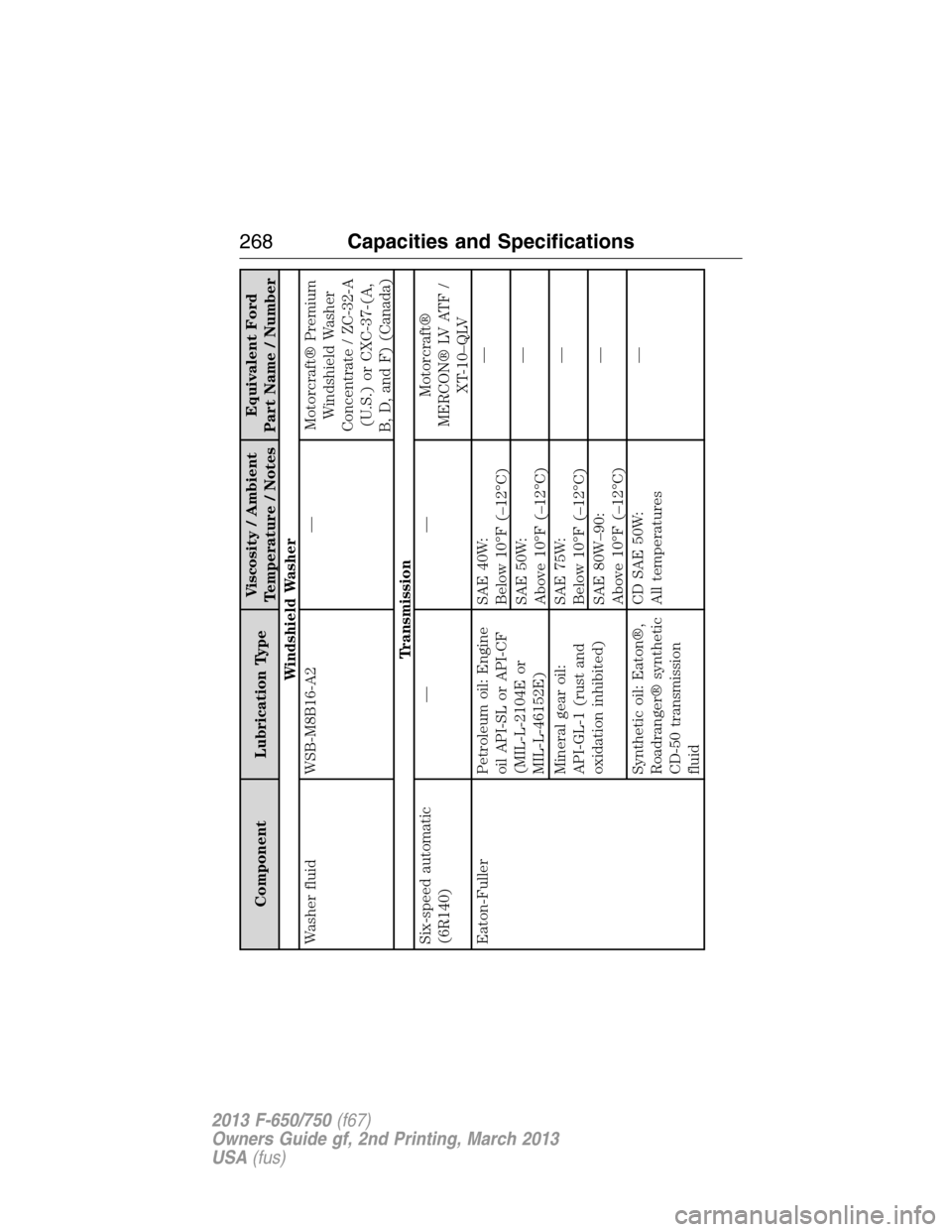
Component Lubrication TypeViscosity / Ambient
Temperature / NotesEquivalent Ford
Part Name / Number
Windshield Washer
Washer fluid WSB-M8B16-A2 — Motorcraft® Premium
Windshield Washer
Concentrate / ZC-32-A
(U.S.) or CXC-37-(A,
B, D, and F) (Canada)
Transmission
Six-speed automatic
(6R140)— — Motorcraft®
MERCON® LV ATF /
XT-10–QLV
Eaton-Fuller Petroleum oil: Engine
oil API-SL or API-CF
(MIL-L-2104E or
MIL-L-46152E)SAE 40W:
Below 10°F (–12°C)—
SAE 50W:
Above 10°F (–12°C)—
Mineral gear oil:
API-GL-1 (rust and
oxidation inhibited)SAE 75W:
Below 10°F (–12°C)—
SAE 80W–90:
Above 10°F (–12°C)—
Synthetic oil: Eaton®,
Roadranger® synthetic
CD-50 transmission
fluidCD SAE 50W:
All temperatures—
268Capacities and Specifications
2013 F-650/750(f67)
Owners Guide gf, 2nd Printing, March 2013
USA(fus)