Axle FORD F650 2017 13.G User Guide
[x] Cancel search | Manufacturer: FORD, Model Year: 2017, Model line: F650, Model: FORD F650 2017 13.GPages: 382, PDF Size: 5.18 MB
Page 177 of 382
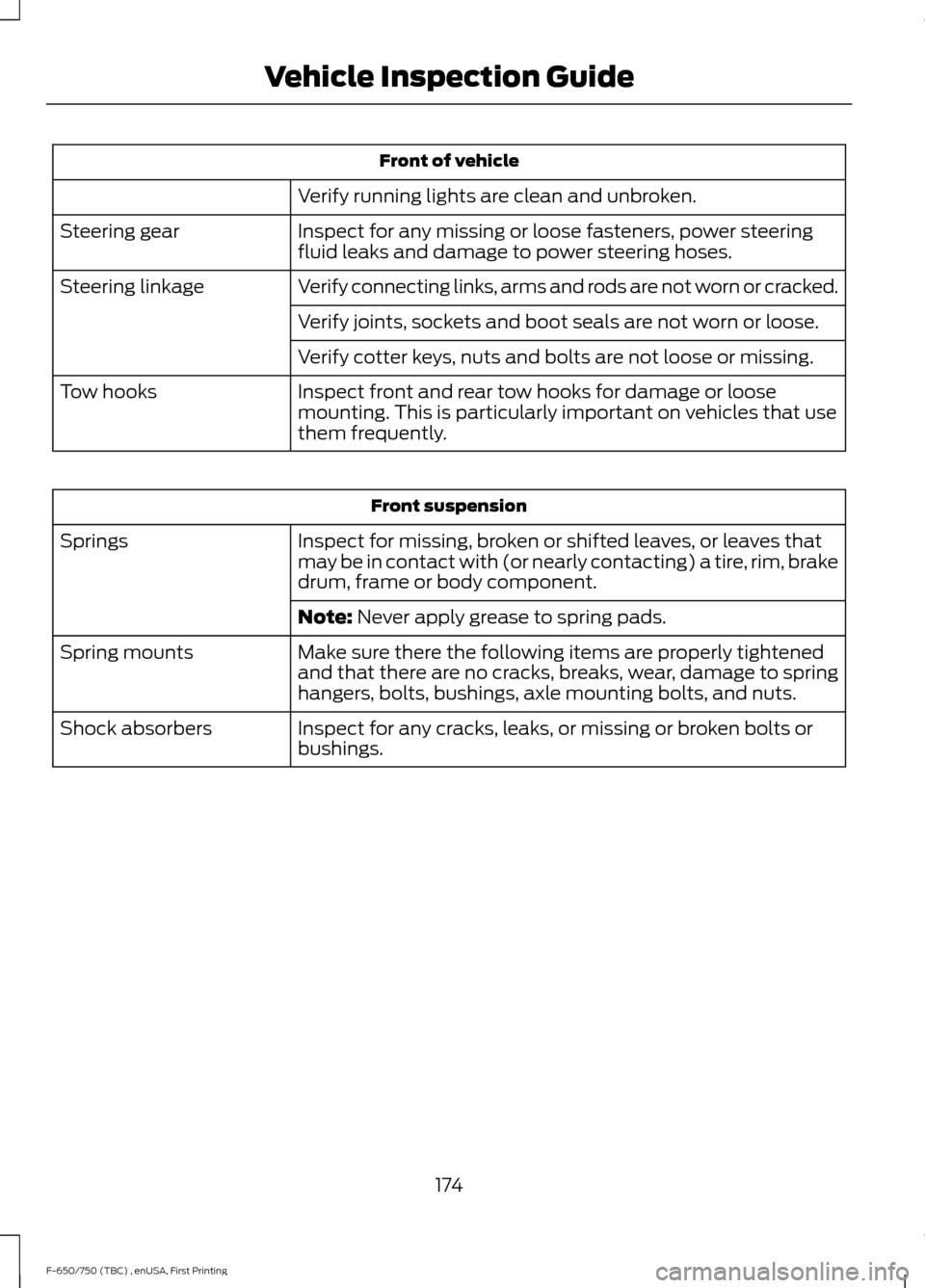
Front of vehicle
Verify running lights are clean and unbroken.
Inspect for any missing or loose fasteners, power steering
fluid leaks and damage to power steering hoses.
Steering gear
Verify connecting links, arms and rods are not worn or cracked.
Steering linkage
Verify joints, sockets and boot seals are not worn or loose.
Verify cotter keys, nuts and bolts are not loose or missing.
Inspect front and rear tow hooks for damage or loose
mounting. This is particularly important on vehicles that use
them frequently.
Tow hooks Front suspension
Inspect for missing, broken or shifted leaves, or leaves that
may be in contact with (or nearly contacting) a tire, rim, brake
drum, frame or body component.
Springs
Note: Never apply grease to spring pads.
Make sure there the following items are properly tightened
and that there are no cracks, breaks, wear, damage to spring
hangers, bolts, bushings, axle mounting bolts, and nuts.
Spring mounts
Inspect for any cracks, leaks, or missing or broken bolts or
bushings.
Shock absorbers
174
F-650/750 (TBC) , enUSA, First Printing Vehicle Inspection Guide
Page 180 of 382
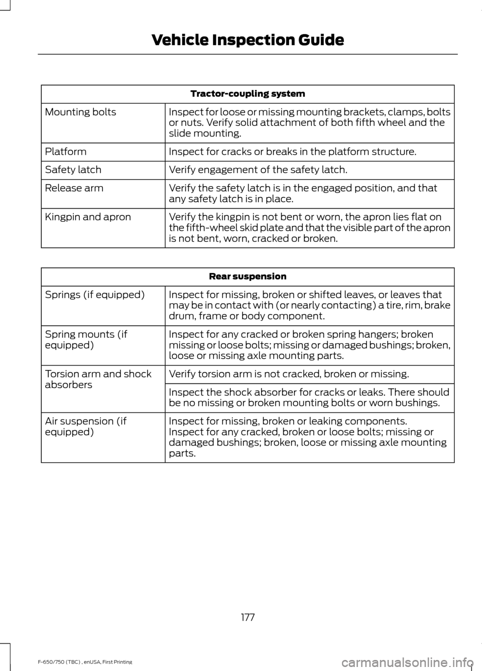
Tractor-coupling system
Inspect for loose or missing mounting brackets, clamps, bolts
or nuts. Verify solid attachment of both fifth wheel and the
slide mounting.
Mounting bolts
Inspect for cracks or breaks in the platform structure.
Platform
Verify engagement of the safety latch.
Safety latch
Verify the safety latch is in the engaged position, and that
any safety latch is in place.
Release arm
Verify the kingpin is not bent or worn, the apron lies flat on
the fifth-wheel skid plate and that the visible part of the apron
is not bent, worn, cracked or broken.
Kingpin and apron Rear suspension
Inspect for missing, broken or shifted leaves, or leaves that
may be in contact with (or nearly contacting) a tire, rim, brake
drum, frame or body component.
Springs (if equipped)
Inspect for any cracked or broken spring hangers; broken
missing or loose bolts; missing or damaged bushings; broken,
loose or missing axle mounting parts.
Spring mounts (if
equipped)
Verify torsion arm is not cracked, broken or missing.
Torsion arm and shock
absorbers
Inspect the shock absorber for cracks or leaks. There should
be no missing or broken mounting bolts or worn bushings.
Inspect for missing, broken or leaking components.
Air suspension (if
equipped) Inspect for any cracked, broken or loose bolts; missing or
damaged bushings; broken, loose or missing axle mounting
parts.
177
F-650/750 (TBC) , enUSA, First Printing Vehicle Inspection Guide
Page 184 of 382
Quality service parts are available through
an authorized dealer. If dealer parts are not
used, make sure the replacement parts are
of equivalent quality.
Working with the Engine Off
1. Set the parking brake and shift to
neutral (N) or park (P).
2. Switch off the engine.
3. Block the wheels.
Working with the Engine On WARNING
To reduce the risk of vehicle damage
and/or personal burn injuries, do not
start your engine with the air cleaner
removed and do not remove it while the
engine is running. 1. Set the parking brake and shift to
neutral (N) or park (P).
2. Block the wheels
Supporting Your Vehicle for
Service WARNING
Do not use a jack when working
under a vehicle. It may give way,
causing the vehicle to fall and result
in property damage, personal injury or
death. Always use floor stands to support
the vehicle. Prepare your vehicle for service repairs by
doing the following:
1. Park your vehicle on a level, concrete
floor.
2. Set the parking brake and block the wheels to prevent your vehicle from
moving. 3. Select a jack with a rated capacity
sufficient to lift and hold up your
vehicle.
4. Raise your vehicle with the jack applied
to the axle(s). Do not use the bumper
as a lifting point.
5. Support your vehicle with floor stands under the axle(s). When servicing the
axle or the suspension, support your
vehicle with floor stands under the
frame side-members, preferably
between the axles.
OPENING AND CLOSING THE
HOOD WARNINGS
Always set the parking brake fully
before opening the hood. Failure to
follow this warning could result in
serious personal injury or death. Do not stand under the hood when
you raise or lower it. Failure to follow
this warning could result in serious
personal injury or death. If the engine is running while the
hood is open, stay clear of moving
engine components. Failure to follow
this warning could result in serious
personal injury or death. Opening the Hood
Before opening the hood, set the parking
brake fully, shift into park (P) or neutral
(N) and switch the ignition off.
181
F-650/750 (TBC) , enUSA, First Printing Maintenance
Page 217 of 382
CHANGING THE ENGINE-
MOUNTED AND DIESEL FUEL
CONDITIONER MODULE FUEL
FILTERS
WARNING
Do not dispose of fuel in the
household refuse or the public
sewage system. Use an authorized
waste disposal facility. Your vehicle has two fuel filters. The first
filter mounts on top of the engine on the
left-hand side. The second filter is inside
the diesel fuel conditioner module. The
module is mounted between the outboard
side of the fuel tank and the frame rail.
Note:
The module is at the front of the fuel
tank or at the front of the aft-axle fuel tank
on some models.
Regular fuel filter changes are an
important part of engine maintenance;
failing to keep with the scheduled
maintenance could lead to engine
performance issues and fuel injection
system damage. See Scheduled
Maintenance (page 316).
Use only recommended service parts
conforming to specifications. See
Motorcraft Parts
(page 255).
Note: Using fuel that has high levels of
impurities may require more frequent filter
replacements than the service interval
specifies.
Diesel Fuel Conditioner Module
Filter
Removal
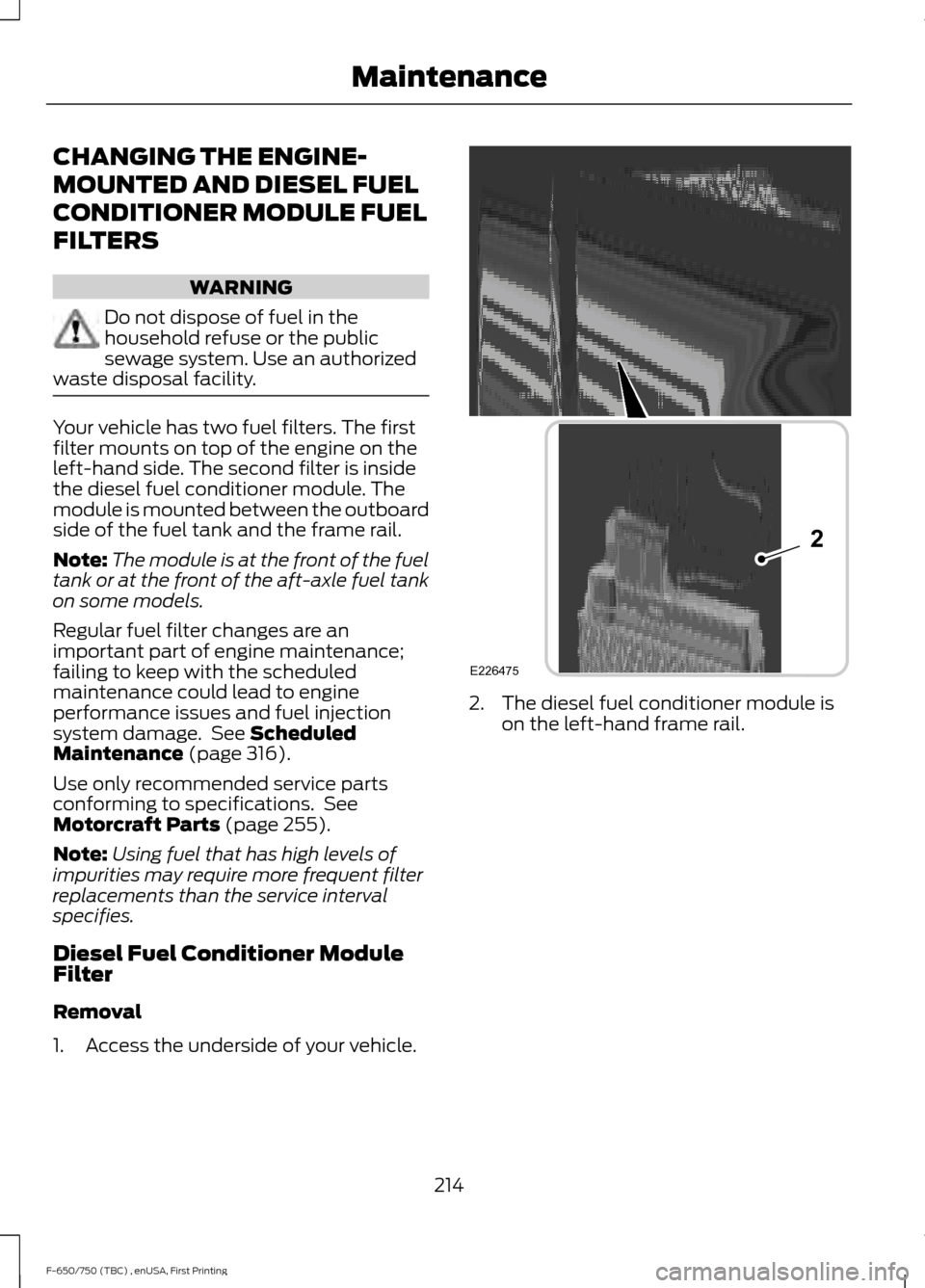
1. Access the underside of your vehicle. 2. The diesel fuel conditioner module is
on the left-hand frame rail.
214
F-650/750 (TBC) , enUSA, First Printing MaintenanceE226475
2
Page 225 of 382
AXLE INSPECTION
Front Axle
Maintaining the front axle alignment to
specifications is very important. A qualified
technician should check and maintain the
alignment.
Regular inspections should include:
•
Toe-in inspection and adjustment (if
necessary), particularly with radial
tires.
• Checking for proper tightness of axle
mounting U-bolt nuts, attaching or
mounting bolts and nuts.
• Checking the axle for damage, binding,
worn parts and adequate lubrication.
• Checking the kingpins for excessive
wear. Also, perform this check during
other scheduled maintenance, for
example as tire rotation or service,
wheel bearing service and alignment.
See the workshop manual for proper
procedures.
Toe-in
It is essential to maintain correct toe-in
and tire pressure for optimum tire wear.
Inspecting steer axle tires in the first
3,000– 10,000 mi (5,000– 16,000 km)
generally shows if tires are wearing
normally.
Rapid outside shoulder wear on both tires
indicates too much toe-in.
Rapid inside shoulder wear on both tires
indicates too much toe-out.
In P&D-type service, there can be a
left-to-right steer tire tread life differential
up to 40% depending on routes and other
variables. Follow the tire manufacturer's
recommended cold inflation pressure for
the tire size, load range (ply rating) and
steer axle loading typical for their operation
(each steer axle tire equals ½ steer axle
loading).
Special applications may warrant a setting
based on experience with the type of tire
operating loads and conditions. Radial tires
are more sensitive to toe-in setting than
bias ply tires. Fine tuning school bus
alignment to line-haul truck standards
does not drastically improve tire tread life.
STEERING SYSTEM
INSPECTION
WARNING
Failure to maintain the steering
system in proper condition can cause
reduced steering ability resulting in
property damage, personal injury or death. Note:
Have any steering problems
immediately corrected by a qualified service
technician.
Ask your service technician to examine the
steering mechanism. Only minor
adjustments may be necessary.
Regular inspections should include:
• Checking the tie rod, drag link end
clamp bolts and ball joints for proper
tightness.
• Checking for installation and spread of
cotter pins and tightness of nuts at
both ends of the tie rod and drag link.
• Checking that the pitman arm (steering
arm at steering gear) mounting is tight
and locked. Check system for leaks or
hose chafing. Repair immediately, if
necessary.
222
F-650/750 (TBC) , enUSA, First Printing Maintenance
Page 226 of 382
•
Maintaining proper steering gear and
power steering pump lubricant levels.
• Checking steering column joint bolts
and steering linkage, particularly for
body-to-chassis clearance.
Steering Column Joint Bolts
As a good maintenance practice, check
steering column joint bolt tightness every
60,000 mi (96,000 km) or annually,
whichever occurs first. Do not overtighten
the bolts.
Hydraulic System
Whenever draining and refilling the power
steering's hydraulic system for any reason,
bleed air from the system before returning
the vehicle to service. Failure to bleed the
hydraulic system properly can result in
degradation of power system performance.
Consult an authorized dealer who is aware
of the proper procedures for filling and
bleeding the system.
SUSPENSION SYSTEM
INSPECTION
Note: Do not adjust air suspension height
to any setting other than the specified
setting. Altering the height setting changes
the driveline angle and may result in
unwarrantable component damage, such
as transmission component damage.
Verify drive axle air suspension height and
height control valve performance at engine
oil change intervals.
Periodically check:
• Condition of spring leaves for evidence
of fatigue, bending or breakage.
• Condition of suspension mounting
brackets and bushings.
• Torque rod mounting fasteners for
tightness. •
For proper suspension alignment.
Maintain proper alignment at all times.
• U-bolts. After the chassis has been
operating under load for
1,000 mi
(1,600 km) or six months (whichever
comes first), the U-bolt nuts must be
re-torqued. Re-torque the U-bolt nuts
every
37,000 mi (60,000 km)
thereafter. Clean and lubricate the
U-bolt and nut threads and seats to
make sure a like new condition when
re-torqueing. See
Spring U-Bolt
Check (page 224).
FRAME AND TOW HOOK
INSPECTION
Your vehicle's chassis is manufactured
with frame rails of either HSLA steel or
heat-treated steel. Handle each in a
specific manner to make sure maximum
service life. Consult the service manual or
an authorized dealer before attempting
frame repair or modification.
It is important, particularly on vehicles that
use tow hooks frequently, to inspect the
front and rear tow hooks for damage or a
loose mounting.
REAR AXLE FLUID CHECK
Your rear axle may have an optional
synthetic lubricant that allows the use of
extended service intervals. A tag on the
filler plug identifies the use of the synthetic
lubricant.
Only use a lubricant that meets
manufacturer specifications. Only use a
lubricant that meets manufacturer
specifications. Use of a non-approved rear
axle lubricant may cause internal axle
component damage. See Capacities and
Specifications
(page 258).
223
F-650/750 (TBC) , enUSA, First Printing Maintenance
Page 227 of 382
Checking the Fluid Level
1. Park your vehicle on level ground.
2. Set the parking brake and shift into
position neutral (N) or park (P). Turn
the engine off.
3. Clean any dirt from around the axle filler plug.
4. Remove the filler plug and inspect the lubricant level. It should be at the
bottom of the filler plug opening.
5. Add lubricant, if necessary, through the
filler plug opening.
6. Clean and install the filler plug securely.
Changing the Fluid
Note: Drain the rear axle while the lubricant
is warm.
1. Park your vehicle on level ground.
2. Set the parking brake and shift into position neutral (N) or park (P). Turn
the engine off.
3. Clean any dirt from around the axle filler and drain plugs.
4. Remove the filler and drain plugs. Drain
the lubricant into a suitable container.
Dispose of all used automotive fluids
in a responsible manner following your
local authorized standards.
5. Clean and install the drain plug securely.
6. Add lubricant through the filler plug opening.
7. Clean and install the filler plug securely.
SPRING U-BOLT CHECK
Check and tighten the U-bolt nuts after
your vehicle has been operated under load
for 1,000 mi (1,600 km) or six months,
whichever occurs first. Thereafter, install new U-bolt nuts and
washers every
36,000 mi (58,000 km).
Check and tighten the U-bolt nuts with
your vehicle at curb height and unloaded.
Inspect the U-bolt threads for rust and
debris. Clean the threads if contaminated.
U-bolt Nut Torque
Front Axle
Note: Check and tighten the U-bolt nuts
evenly using a criss-cross pattern in the
following stages. lb.ft (Nm)
Stage
40 (60)
1.
90 (125)
2.
170 (225)
3.
240 (325)
4.
Rear Axle
Note: Check and tighten the U-bolt nuts
evenly using a criss-cross pattern in the
following stages. lb.ft (Nm)
Stage
60 (75)
1.
90 (125)
2.
170 (225)
3.
240 (325)
4.
320 (440)
5.
224
F-650/750 (TBC) , enUSA, First Printing Maintenance
Page 240 of 382
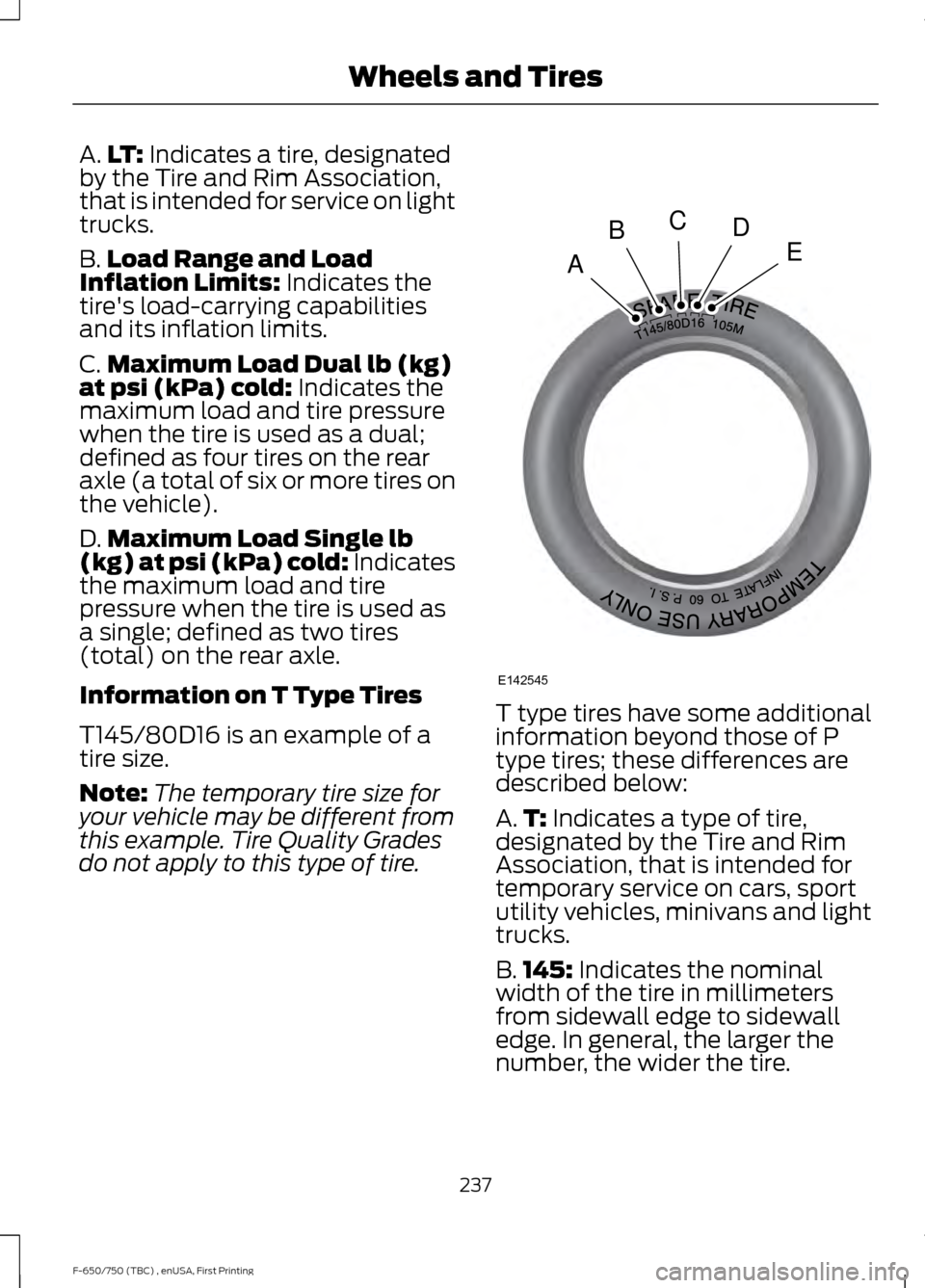
A.
LT: Indicates a tire, designated
by the Tire and Rim Association,
that is intended for service on light
trucks.
B. Load Range and Load
Inflation Limits:
Indicates the
tire's load-carrying capabilities
and its inflation limits.
C. Maximum Load Dual lb (kg)
at psi (kPa) cold:
Indicates the
maximum load and tire pressure
when the tire is used as a dual;
defined as four tires on the rear
axle (a total of six or more tires on
the vehicle).
D. Maximum Load Single lb
(kg) at psi (kPa) cold:
Indicates
the maximum load and tire
pressure when the tire is used as
a single; defined as two tires
(total) on the rear axle.
Information on T Type Tires
T145/80D16 is an example of a
tire size.
Note: The temporary tire size for
your vehicle may be different from
this example. Tire Quality Grades
do not apply to this type of tire. T type tires have some additional
information beyond those of P
type tires; these differences are
described below:
A.
T:
Indicates a type of tire,
designated by the Tire and Rim
Association, that is intended for
temporary service on cars, sport
utility vehicles, minivans and light
trucks.
B. 145:
Indicates the nominal
width of the tire in millimeters
from sidewall edge to sidewall
edge. In general, the larger the
number, the wider the tire.
237
F-650/750 (TBC) , enUSA, First Printing Wheels and TiresA
BCDE
E142545
Page 247 of 382
describes the fundamental
characteristics of the tire and also
provides a U.S. DOT Tire
Identification Number for safety
standard certification and in case
of a recall.
This begins with the letters DOT
and indicates that the tire meets
all federal standards. The next
two numbers or letters are the
plant code designating where it
was manufactured, the next two
are the tire size code and the last
four numbers represent the week
and year the tire was built. For
example, the numbers 317 mean
the 31st week of 1997. After 2000
the numbers go to four digits. For
example, 2501 means the 25th
week of 2001. The numbers in
between are identification codes
used for traceability. This
information is used to contact
customers if a tire defect requires
a recall.
Tire Replacement
Requirements
Your vehicle is equipped with tires
designed to provide a safe ride
and handling capability.
WARNINGS
Only use replacement tires
and wheels that are the same
size, load index, speed rating and
type (such as P-metric versus
LT-metric or all-season versus
all-terrain) as those originally
provided by Ford. The
recommended tire and wheel size WARNINGS
may be found on either the Safety
Compliance Certification Label or
the Tire Label. If this information
is not found on these labels then
you should contact your
authorized dealer as soon as
possible. Use of any tire or wheel
not recommended by Ford can
affect the safety and performance
of your vehicle, which could result
in an increased risk of loss of
vehicle control, vehicle rollover,
personal injury and death.
Additionally the use of
non-recommended tires and
wheels could cause steering,
suspension, axle, transfer case or
power transfer unit failure. If you
have questions regarding tire
replacement, contact your
authorized dealer as soon as
possible. To reduce the risk of serious
injury, when mounting
replacement tires and wheels, you
should not exceed the maximum
pressure indicated on the sidewall
of the tire to set the beads without
additional precautions listed
below. If the beads do not seat at
the maximum pressure indicated,
re-lubricate and try again
244
F-650/750 (TBC) , enUSA, First Printing Wheels and Tires
Page 250 of 382
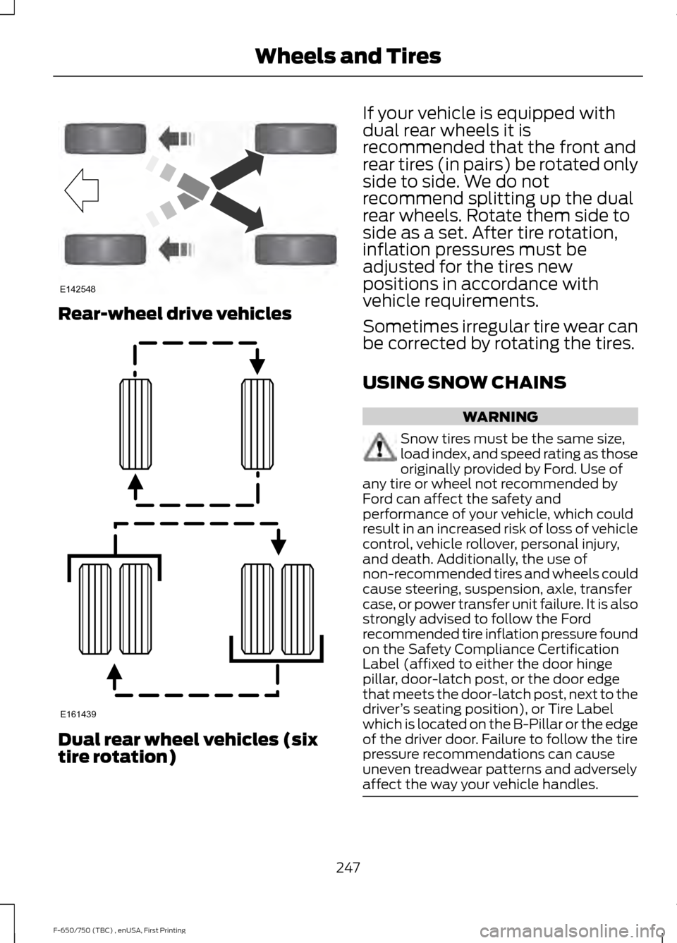
Rear-wheel drive vehicles
Dual rear wheel vehicles (six
tire rotation) If your vehicle is equipped with
dual rear wheels it is
recommended that the front and
rear tires (in pairs) be rotated only
side to side. We do not
recommend splitting up the dual
rear wheels. Rotate them side to
side as a set. After tire rotation,
inflation pressures must be
adjusted for the tires new
positions in accordance with
vehicle requirements.
Sometimes irregular tire wear can
be corrected by rotating the tires.
USING SNOW CHAINS
WARNING
Snow tires must be the same size,
load index, and speed rating as those
originally provided by Ford. Use of
any tire or wheel not recommended by
Ford can affect the safety and
performance of your vehicle, which could
result in an increased risk of loss of vehicle
control, vehicle rollover, personal injury,
and death. Additionally, the use of
non-recommended tires and wheels could
cause steering, suspension, axle, transfer
case, or power transfer unit failure. It is also
strongly advised to follow the Ford
recommended tire inflation pressure found
on the Safety Compliance Certification
Label (affixed to either the door hinge
pillar, door-latch post, or the door edge
that meets the door-latch post, next to the
driver ’s seating position), or Tire Label
which is located on the B-Pillar or the edge
of the driver door. Failure to follow the tire
pressure recommendations can cause
uneven treadwear patterns and adversely
affect the way your vehicle handles. 247
F-650/750 (TBC) , enUSA, First Printing Wheels and TiresE142548 E161439