brake fluid FORD F650 2017 13.G User Guide
[x] Cancel search | Manufacturer: FORD, Model Year: 2017, Model line: F650, Model: FORD F650 2017 13.GPages: 382, PDF Size: 5.18 MB
Page 126 of 382
FULL POWER BRAKE
WARNING
If the brake warning lamp in the
instrument cluster remains
illuminated after engine start up, this
indicates a system failure in the Full Power
Brake system. Stop the vehicle safely as
soon as possible and seek service
immediately. This system incorporates standard braking,
an anti-lock braking system (ABS) and
optional Power Park Brake into one fully
integrated hydraulic brake system. With
the Full Power Brake system, braking
energy is stored, similar to an air brake
system, resulting in faster response times
and shorter stopping distances. This is
accomplished using motor and pump
assemblies that pressurize the system by
pumping brake fluid into accumulators.
This is similar to the air compressor of an
air brake system pressurizing the air tanks.
The system includes a master cylinder that
provides the normal pedal feel and
transfers the pedal force, via brake fluid,
to the main components of the system.
Note:
The motor and pumps run
momentarily with the ignition switch in the
on or run position, or in the off position with
the brake pedal pressed.
Note: During normal driving, you may hear
the pump and motors replenishing the
accumulators. This is a normal function of
the system. AIR BRAKES WARNINGS
Do not drive or continue to drive if the
low air pressure buzzer is sounding
or the brake warning light is lit. These
warnings indicate that air pressure is not
to normal operating level. Continued use
of the vehicle could result in loss of braking
ability. Avoid repeated light application of
the brake pedal. This depletes air
pressure faster and could result in
loss of braking capability. Do not move the vehicle when the
air pressure is insufficient because
the brake system may be inoperative.
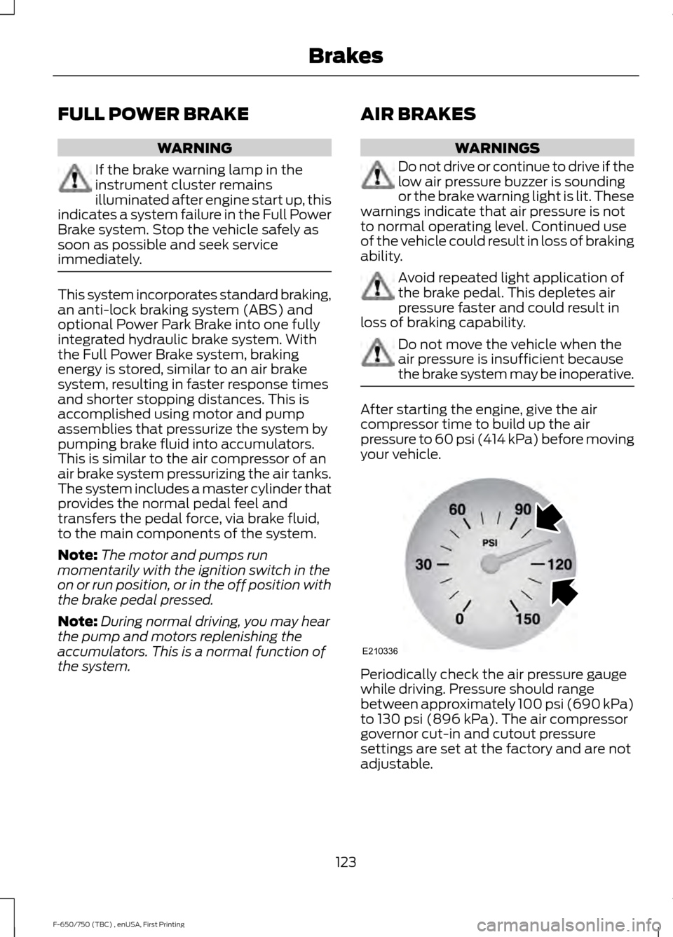
After starting the engine, give the air
compressor time to build up the air
pressure to 60 psi (414 kPa) before moving
your vehicle. Periodically check the air pressure gauge
while driving. Pressure should range
between approximately 100 psi (690 kPa)
to
130 psi (896 kPa). The air compressor
governor cut-in and cutout pressure
settings are set at the factory and are not
adjustable.
123
F-650/750 (TBC) , enUSA, First Printing BrakesE210336
Page 174 of 382
VEHICLE INSPECTION
INFORMATION
To make sure your vehicle is ready to
operate, conduct a pre-trip inspection at
the beginning of each work period. Follow
the steps listed in this section to verify a
proper vehicle inspection procedure.
WARNINGS
Exercise great caution when working
on a vehicle equipped with an
automatic fan clutch. The fan starts
in motion only after the engine coolant
reaches a predetermined temperature or
the refrigerant pressure (if equipped with
air conditioning) reaches a predetermined
setting. The fan starts at this point with no
advance warning. Never reach near, or
permit objects to protrude into, the fan
blade radius while the engine is running as
this could result in vehicle damage,
personal injury or death. WARNINGS
Do not operate the vehicle if any
suspension conditions listed in the
following charts are evident. Loss of
steering or suspension could result in
property damage, personal injury or death. If a wheel must be changed, obtain
expert tire service help. Mounting and
un-mounting of tires should only be
performed by a qualified technician using
necessary safety procedures and
equipment, otherwise the result could be
property damage, personal injury or death. Note:
Always make sure you apply the
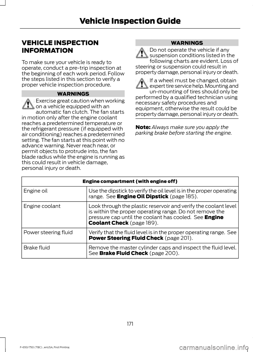
parking brake before starting the engine. Engine compartment (with engine off)
Use the dipstick to verify the oil level is in the proper operating
range. See Engine Oil Dipstick (page 185).
Engine oil
Look through the plastic reservoir and verify the coolant level
is within the proper operating range. Do not remove the
pressure cap until the coolant has cooled. See
Engine
Coolant Check (page 189).
Engine coolant
Verify that the fluid level is in the proper operating range. See
Power Steering Fluid Check
(page 201).
Power steering fluid
Remove the master cylinder caps and inspect the fluid level.
See
Brake Fluid Check (page 200).
Brake fluid
171
F-650/750 (TBC) , enUSA, First Printing Vehicle Inspection Guide
Page 175 of 382
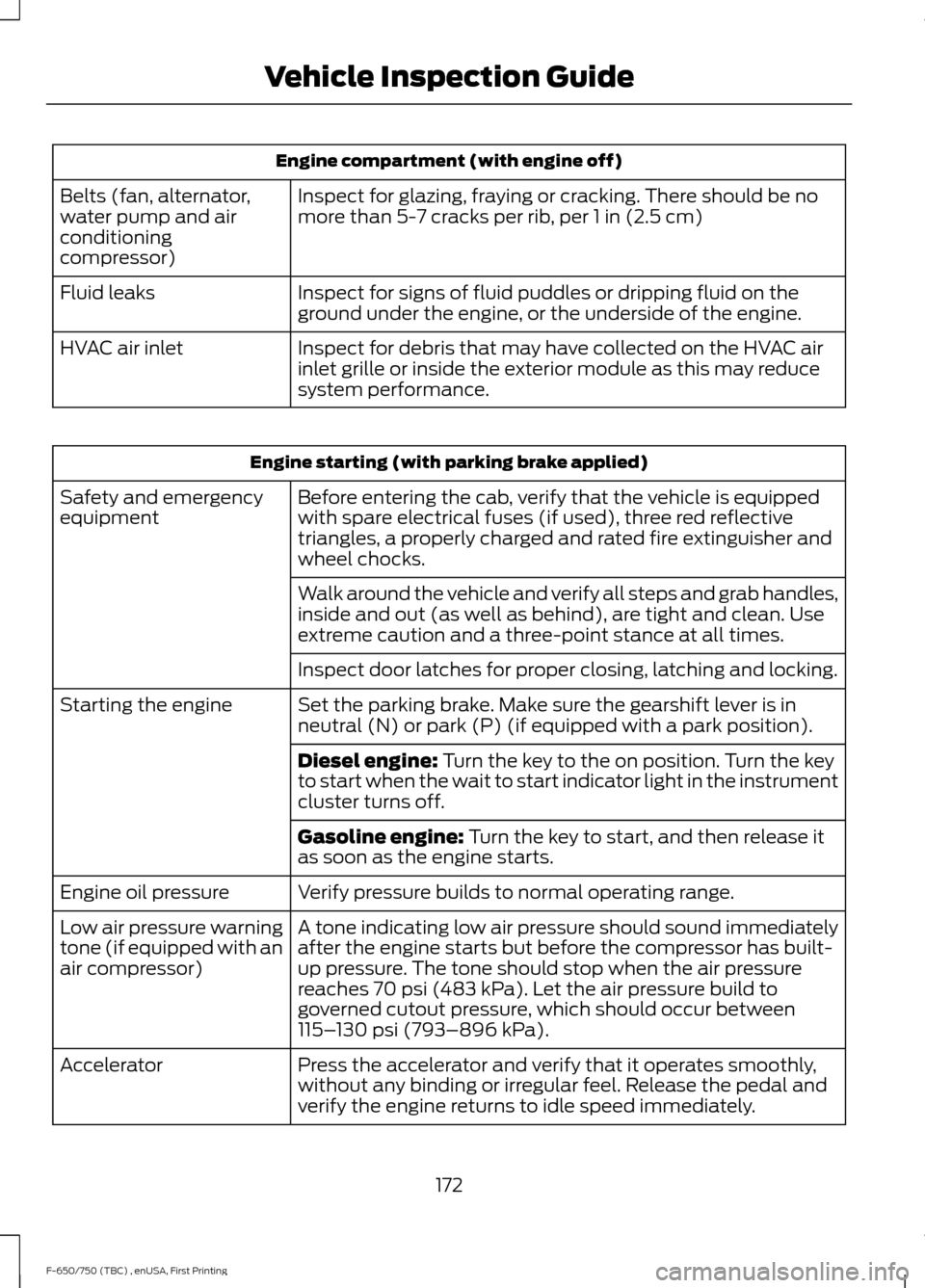
Engine compartment (with engine off)
Inspect for glazing, fraying or cracking. There should be no
more than 5-7 cracks per rib, per 1 in (2.5 cm)
Belts (fan, alternator,
water pump and air
conditioning
compressor)
Inspect for signs of fluid puddles or dripping fluid on the
ground under the engine, or the underside of the engine.
Fluid leaks
Inspect for debris that may have collected on the HVAC air
inlet grille or inside the exterior module as this may reduce
system performance.
HVAC air inlet Engine starting (with parking brake applied)
Before entering the cab, verify that the vehicle is equipped
with spare electrical fuses (if used), three red reflective
triangles, a properly charged and rated fire extinguisher and
wheel chocks.
Safety and emergency
equipment
Walk around the vehicle and verify all steps and grab handles,
inside and out (as well as behind), are tight and clean. Use
extreme caution and a three-point stance at all times.
Inspect door latches for proper closing, latching and locking.
Set the parking brake. Make sure the gearshift lever is in
neutral (N) or park (P) (if equipped with a park position).
Starting the engine
Diesel engine:
Turn the key to the on position. Turn the key
to start when the wait to start indicator light in the instrument
cluster turns off.
Gasoline engine:
Turn the key to start, and then release it
as soon as the engine starts.
Verify pressure builds to normal operating range.
Engine oil pressure
A tone indicating low air pressure should sound immediately
after the engine starts but before the compressor has built-
up pressure. The tone should stop when the air pressure
reaches
70 psi (483 kPa). Let the air pressure build to
governed cutout pressure, which should occur between
115– 130 psi (793–896 kPa)
.
Low air pressure warning
tone (if equipped with an
air compressor)
Press the accelerator and verify that it operates smoothly,
without any binding or irregular feel. Release the pedal and
verify the engine returns to idle speed immediately.
Accelerator
172
F-650/750 (TBC) , enUSA, First Printing Vehicle Inspection Guide
Page 176 of 382
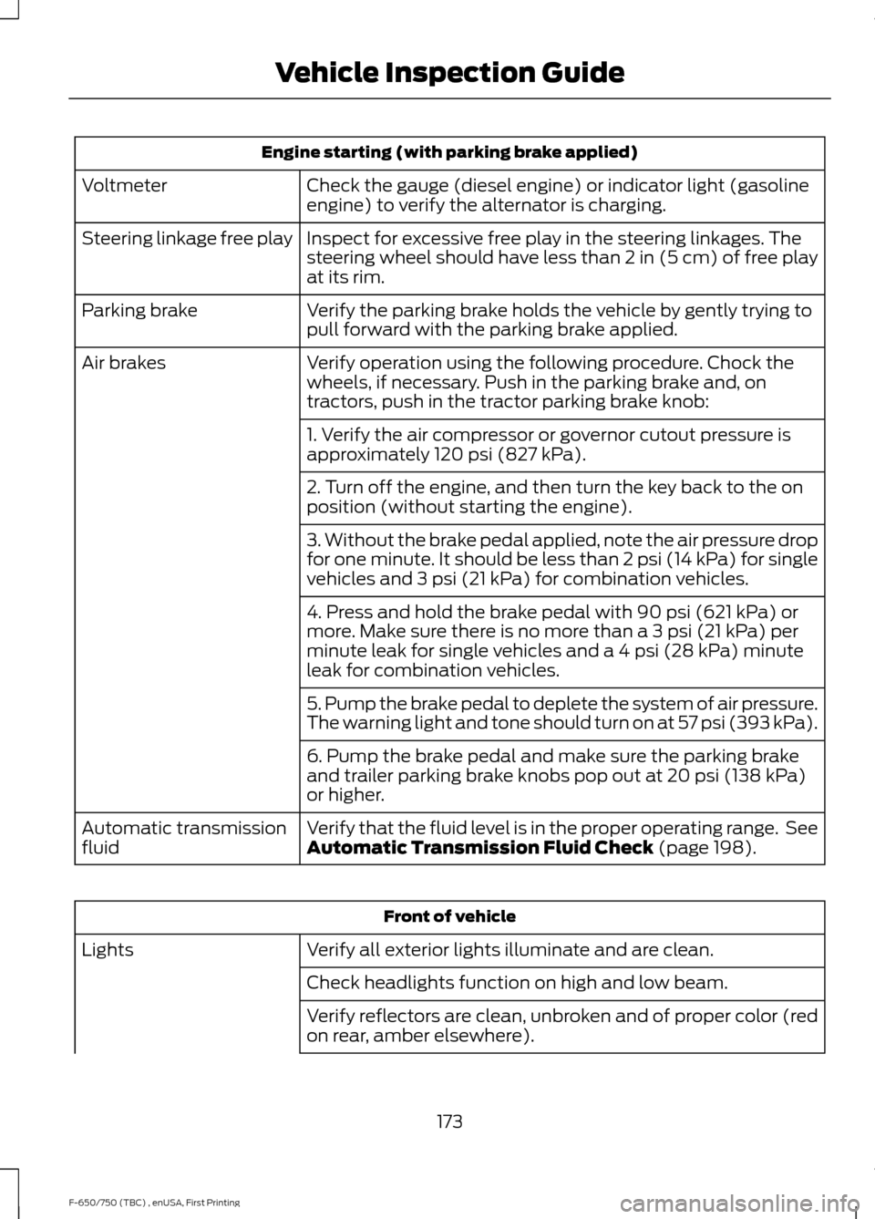
Engine starting (with parking brake applied)
Check the gauge (diesel engine) or indicator light (gasoline
engine) to verify the alternator is charging.
Voltmeter
Inspect for excessive free play in the steering linkages. The
steering wheel should have less than 2 in (5 cm) of free play
at its rim.
Steering linkage free play
Verify the parking brake holds the vehicle by gently trying to
pull forward with the parking brake applied.
Parking brake
Verify operation using the following procedure. Chock the
wheels, if necessary. Push in the parking brake and, on
tractors, push in the tractor parking brake knob:
Air brakes
1. Verify the air compressor or governor cutout pressure is
approximately 120 psi (827 kPa).
2. Turn off the engine, and then turn the key back to the on
position (without starting the engine).
3. Without the brake pedal applied, note the air pressure drop
for one minute. It should be less than 2 psi (14 kPa) for single
vehicles and
3 psi (21 kPa) for combination vehicles.
4. Press and hold the brake pedal with
90 psi (621 kPa) or
more. Make sure there is no more than a 3 psi (21 kPa) per
minute leak for single vehicles and a 4 psi (28 kPa) minute
leak for combination vehicles.
5. Pump the brake pedal to deplete the system of air pressure.
The warning light and tone should turn on at 57 psi (393 kPa).
6. Pump the brake pedal and make sure the parking brake
and trailer parking brake knobs pop out at
20 psi (138 kPa)
or higher.
Verify that the fluid level is in the proper operating range. See
Automatic Transmission Fluid Check
(page 198).
Automatic transmission
fluid Front of vehicle
Verify all exterior lights illuminate and are clean.
Lights
Check headlights function on high and low beam.
Verify reflectors are clean, unbroken and of proper color (red
on rear, amber elsewhere).
173
F-650/750 (TBC) , enUSA, First Printing Vehicle Inspection Guide
Page 177 of 382
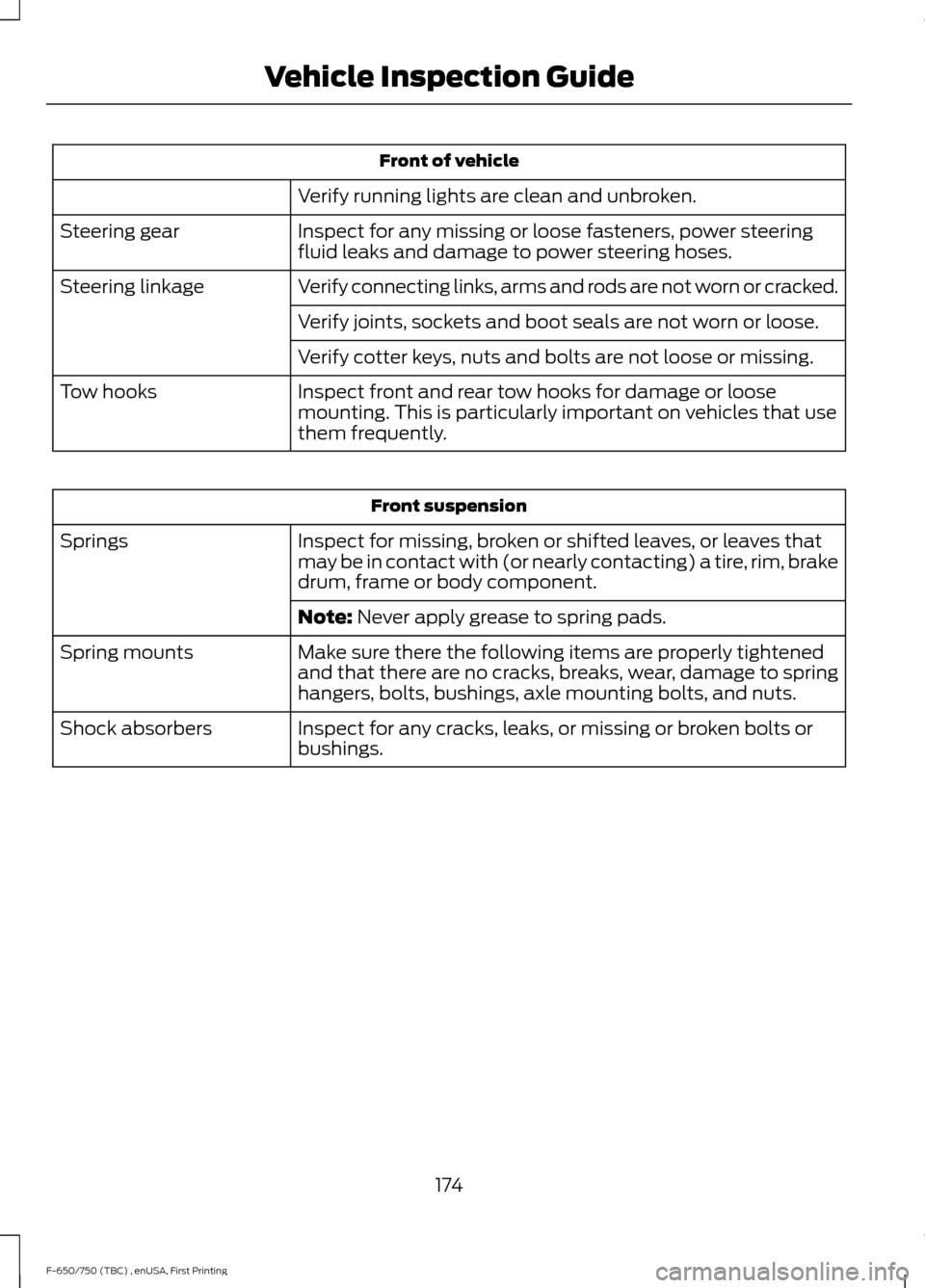
Front of vehicle
Verify running lights are clean and unbroken.
Inspect for any missing or loose fasteners, power steering
fluid leaks and damage to power steering hoses.
Steering gear
Verify connecting links, arms and rods are not worn or cracked.
Steering linkage
Verify joints, sockets and boot seals are not worn or loose.
Verify cotter keys, nuts and bolts are not loose or missing.
Inspect front and rear tow hooks for damage or loose
mounting. This is particularly important on vehicles that use
them frequently.
Tow hooks Front suspension
Inspect for missing, broken or shifted leaves, or leaves that
may be in contact with (or nearly contacting) a tire, rim, brake
drum, frame or body component.
Springs
Note: Never apply grease to spring pads.
Make sure there the following items are properly tightened
and that there are no cracks, breaks, wear, damage to spring
hangers, bolts, bushings, axle mounting bolts, and nuts.
Spring mounts
Inspect for any cracks, leaks, or missing or broken bolts or
bushings.
Shock absorbers
174
F-650/750 (TBC) , enUSA, First Printing Vehicle Inspection Guide
Page 179 of 382
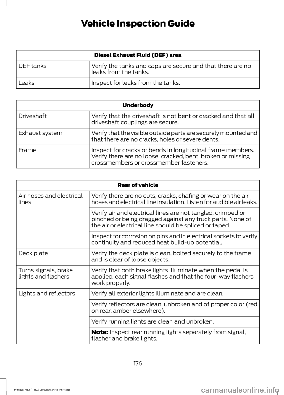
Diesel Exhaust Fluid (DEF) area
Verify the tanks and caps are secure and that there are no
leaks from the tanks.
DEF tanks
Inspect for leaks from the tanks.
Leaks Underbody
Verify that the driveshaft is not bent or cracked and that all
driveshaft couplings are secure.
Driveshaft
Verify that the visible outside parts are securely mounted and
that there are no cracks, holes or severe dents.
Exhaust system
Inspect for cracks or bends in longitudinal frame members.
Verify there are no loose, cracked, bent, broken or missing
crossmembers or crossmember fasteners.
Frame Rear of vehicle
Verify there are no cuts, cracks, chafing or wear on the air
hoses and electrical line insulation. Listen for audible air leaks.
Air hoses and electrical
lines
Verify air and electrical lines are not tangled, crimped or
pinched or being dragged against any truck parts. None of
the air or electrical line should be spliced or taped.
Inspect for corrosion on pins and in electrical sockets to verify
continuity and reduced heat build-up potential.
Verify the deck plate is clean, bolted securely to the frame
and is clear of loose objects.
Deck plate
Verify that both brake lights illuminate when the pedal is
applied, each signal flashes and that the four-way flashers
work properly.
Turns signals, brake
lights and flashers
Verify all exterior lights illuminate and are clean.
Lights and reflectors
Verify reflectors are clean, unbroken and of proper color (red
on rear, amber elsewhere).
Verify running lights are clean and unbroken.
Note: Inspect rear running lights separately from signal,
flasher and brake lights.
176
F-650/750 (TBC) , enUSA, First Printing Vehicle Inspection Guide
Page 183 of 382
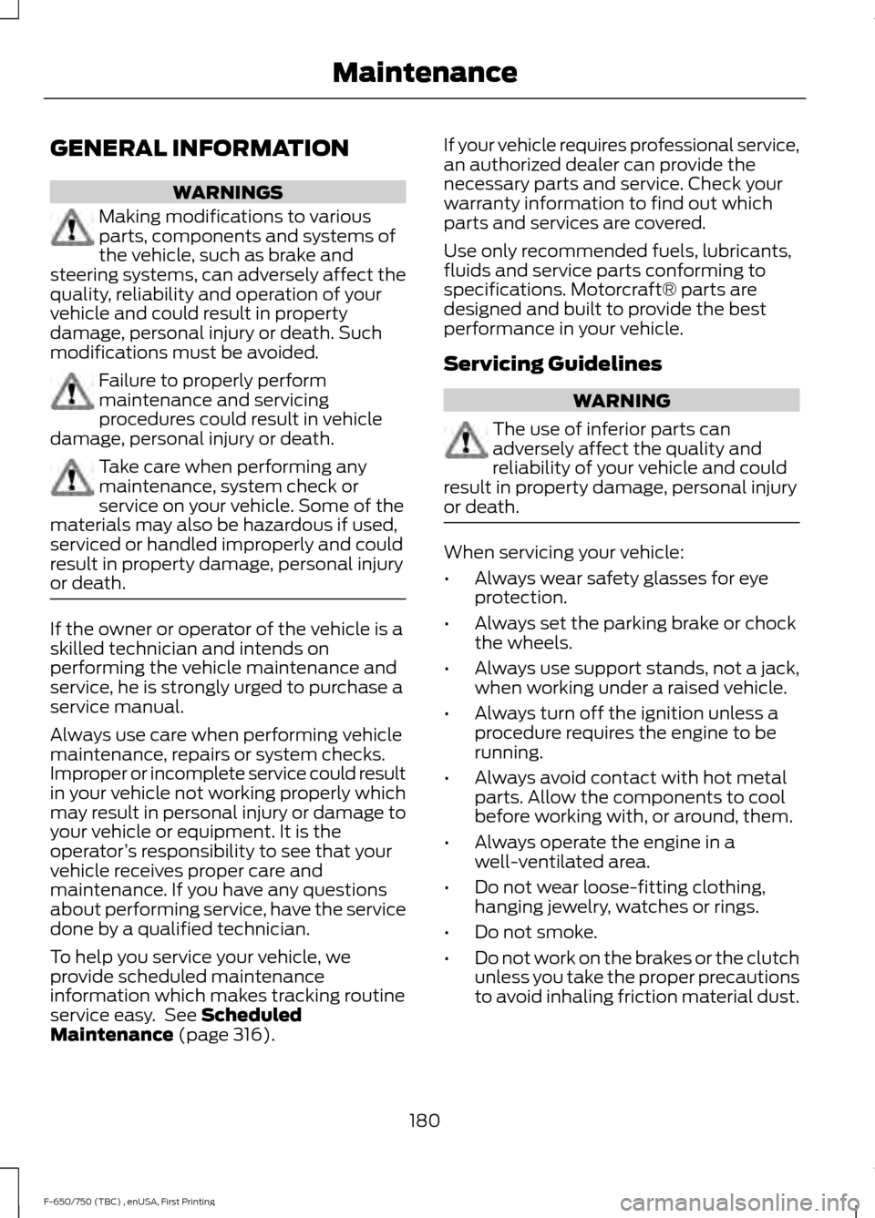
GENERAL INFORMATION
WARNINGS
Making modifications to various
parts, components and systems of
the vehicle, such as brake and
steering systems, can adversely affect the
quality, reliability and operation of your
vehicle and could result in property
damage, personal injury or death. Such
modifications must be avoided. Failure to properly perform
maintenance and servicing
procedures could result in vehicle
damage, personal injury or death. Take care when performing any
maintenance, system check or
service on your vehicle. Some of the
materials may also be hazardous if used,
serviced or handled improperly and could
result in property damage, personal injury
or death. If the owner or operator of the vehicle is a
skilled technician and intends on
performing the vehicle maintenance and
service, he is strongly urged to purchase a
service manual.
Always use care when performing vehicle
maintenance, repairs or system checks.
Improper or incomplete service could result
in your vehicle not working properly which
may result in personal injury or damage to
your vehicle or equipment. It is the
operator
’s responsibility to see that your
vehicle receives proper care and
maintenance. If you have any questions
about performing service, have the service
done by a qualified technician.
To help you service your vehicle, we
provide scheduled maintenance
information which makes tracking routine
service easy. See Scheduled
Maintenance (page 316). If your vehicle requires professional service,
an authorized dealer can provide the
necessary parts and service. Check your
warranty information to find out which
parts and services are covered.
Use only recommended fuels, lubricants,
fluids and service parts conforming to
specifications. Motorcraft® parts are
designed and built to provide the best
performance in your vehicle.
Servicing Guidelines
WARNING
The use of inferior parts can
adversely affect the quality and
reliability of your vehicle and could
result in property damage, personal injury
or death. When servicing your vehicle:
•
Always wear safety glasses for eye
protection.
• Always set the parking brake or chock
the wheels.
• Always use support stands, not a jack,
when working under a raised vehicle.
• Always turn off the ignition unless a
procedure requires the engine to be
running.
• Always avoid contact with hot metal
parts. Allow the components to cool
before working with, or around, them.
• Always operate the engine in a
well-ventilated area.
• Do not wear loose-fitting clothing,
hanging jewelry, watches or rings.
• Do not smoke.
• Do not work on the brakes or the clutch
unless you take the proper precautions
to avoid inhaling friction material dust.
180
F-650/750 (TBC) , enUSA, First Printing Maintenance
Page 186 of 382
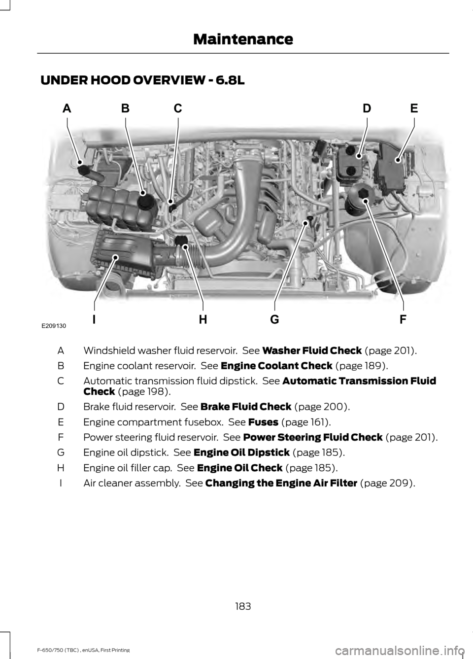
UNDER HOOD OVERVIEW - 6.8L
Windshield washer fluid reservoir. See Washer Fluid Check (page 201).
A
Engine coolant reservoir. See
Engine Coolant Check (page 189).
B
Automatic transmission fluid dipstick. See
Automatic Transmission Fluid
Check (page 198).
C
Brake fluid reservoir. See
Brake Fluid Check (page 200).
D
Engine compartment fusebox. See
Fuses (page 161).
E
Power steering fluid reservoir. See
Power Steering Fluid Check (page 201).
F
Engine oil dipstick. See
Engine Oil Dipstick (page 185).
G
Engine oil filler cap. See
Engine Oil Check (page 185).
H
Air cleaner assembly. See
Changing the Engine Air Filter (page 209).
I
183
F-650/750 (TBC) , enUSA, First Printing MaintenanceABC
FGHI
DE
E209130
Page 187 of 382
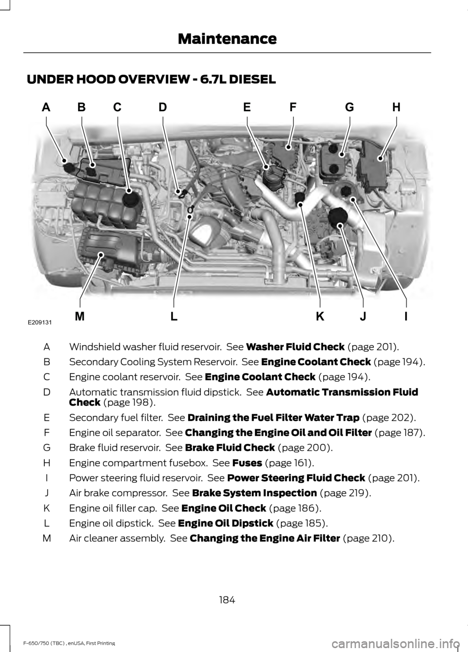
UNDER HOOD OVERVIEW - 6.7L DIESEL
Windshield washer fluid reservoir. See Washer Fluid Check (page 201).
A
Secondary Cooling System Reservoir. See Engine Coolant Check (page 194).
B
Engine coolant reservoir. See
Engine Coolant Check (page 194).
C
Automatic transmission fluid dipstick. See
Automatic Transmission Fluid
Check (page 198).
D
Secondary fuel filter. See
Draining the Fuel Filter Water Trap (page 202).
E
Engine oil separator. See Changing the Engine Oil and Oil Filter (page 187).
F
Brake fluid reservoir. See
Brake Fluid Check (page 200).
G
Engine compartment fusebox. See
Fuses (page 161).
H
Power steering fluid reservoir. See
Power Steering Fluid Check (page 201).
I
Air brake compressor. See
Brake System Inspection (page 219).
J
Engine oil filler cap. See
Engine Oil Check (page 186).
K
Engine oil dipstick. See
Engine Oil Dipstick (page 185).
L
Air cleaner assembly. See
Changing the Engine Air Filter (page 210).
M
184
F-650/750 (TBC) , enUSA, First Printing MaintenanceABD
IJKLM
FEGH
E209131C
Page 202 of 382
The transmission fluid and filter on your
vehicle must be replaced at the specified
service interval. See Scheduled
Maintenance (page 316).
Automatic transmission fluid expands
when warmed. To check the fluid level
consistently and accurately, do the
following:
1. Drive the vehicle until it reaches normal
operating temperature. This may take
up to
20 mi (30 km).
2. Make sure that your vehicle is on level ground.
3. With the engine running, parking brake
engaged and your foot on the brake
pedal, move the gearshift lever through
all of the gear ranges. Allow sufficient
time for each gear to engage.
4. Make sure the parking brake is on. Make
sure the transmission is in park (P) or
neutral (N) and leave the engine
running.
5. Open the hood. See
Opening and
Closing the Hood (page 181).
6. Remove the dipstick and wipe it with a clean, lint-free cloth. See
Under
Hood Overview (page 183).
7. Replace the dipstick and remove it again to check the fluid level.
8. If the fluid level is correct, replace the dipstick and make sure it is fully seated.
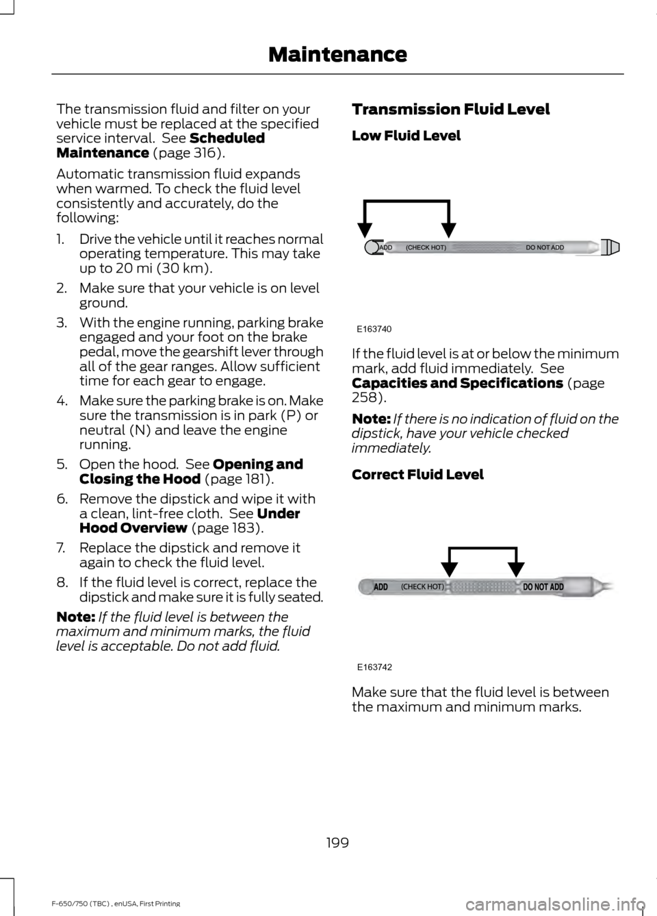
Note: If the fluid level is between the
maximum and minimum marks, the fluid
level is acceptable. Do not add fluid. Transmission Fluid Level
Low Fluid Level
If the fluid level is at or below the minimum
mark, add fluid immediately. See
Capacities and Specifications
(page
258).
Note: If there is no indication of fluid on the
dipstick, have your vehicle checked
immediately.
Correct Fluid Level Make sure that the fluid level is between
the maximum and minimum marks.
199
F-650/750 (TBC) , enUSA, First Printing MaintenanceE163740 E163742