trailer FORD F650 2017 13.G Owner's Manual
[x] Cancel search | Manufacturer: FORD, Model Year: 2017, Model line: F650, Model: FORD F650 2017 13.GPages: 382, PDF Size: 5.18 MB
Page 151 of 382
ROADSIDE ASSISTANCE
Vehicles Sold in the United States:
Getting Roadside Assistance
To fully assist you should you have a
vehicle concern, Ford Motor Company
offers a complimentary roadside
assistance program. This program is
separate from the New Vehicle Limited
Warranty. The service is available:
•
24 hours a day, seven days a week.
• For the coverage period listed on the
Roadside Assistance Card included in
your Owner's Manual portfolio.
Roadside Assistance covers:
• A flat tire change with a good spare, if
provided with the vehicle (except
vehicles supplied with a tire inflation
kit).
• Battery jump start.
• Lock-out assistance (key replacement
cost is the customer's responsibility).
• Fuel delivery — independent service
contractors, if not prohibited by state,
local or municipal law, shall deliver up
to 2 gal (7.6 L) of gasoline or 5 gal
(18.9 L) of diesel fuel to a disabled
vehicle. Roadside Assistance limits fuel
delivery service to two no-charge
occurrences within a 12-month period.
• Winch out — available within
100 ft
(30.5 m) of a paved or county
maintained road, no recoveries.
• Towing — independent service
contractors, if not prohibited by state,
local or municipal law, shall tow Ford
eligible vehicles to an authorized dealer
within
35 mi (56 km) of the
disablement location or to the nearest authorized dealer. If a member
requests a tow to an authorized dealer
that is more than
35 mi (56 km) from
the disablement location, the member
shall be responsible for any mileage
costs in excess of
35 mi (56 km).
Roadside Assistance includes up to $200
for a towed trailer if the disabled eligible
vehicle requires service at the nearest
authorized dealer. If the towing vehicle is
operational but the trailer is not, then the
trailer does not qualify for any roadside
services.
Vehicles Sold in the United States:
Using Roadside Assistance
Complete the roadside assistance
identification card and place it in your
wallet for quick reference. This card is in
the owner's information portfolio in the
glove compartment.
United States Ford vehicle customers who
require Roadside Assistance, call
1-800-241-3673.
If you need to arrange roadside assistance
for yourself, Ford Motor Company
reimburses a reasonable amount for
towing to the nearest dealership within
35 mi (56 km)
. To obtain reimbursement
information, United States Ford vehicle
customers call 1-800-241-3673.
Customers need to submit their original
receipts.
Vehicles Sold in Canada: Getting
Roadside Assistance
To fully assist you should you have a
vehicle concern, Ford Motor Company of
Canada, Limited offers a complimentary
roadside assistance program. This program
is eligible within Canada or the continental
United States.
148
F-650/750 (TBC) , enUSA, First Printing Roadside Emergencies
Page 164 of 382
FUSE SPECIFICATION CHART
Power Distribution Box
WARNINGS
Always disconnect the battery before
servicing high current fuses.
To reduce risk of electrical shock,
always replace the cover to the
power distribution box before
reconnecting the battery or refilling fluid
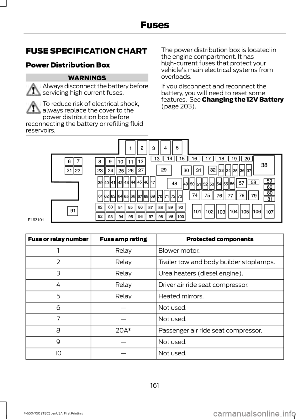
reservoirs. The power distribution box is located in
the engine compartment. It has
high-current fuses that protect your
vehicle's main electrical systems from
overloads.
If you disconnect and reconnect the
battery, you will need to reset some
features. See Changing the 12V Battery
(page 203).
Protected components
Fuse amp rating
Fuse or relay number
Blower motor.
Relay
1
Trailer tow and body builder stoplamps.
Relay
2
Urea heaters (diesel engine).
Relay
3
Driver air ride seat compressor.
Relay
4
Heated mirrors.
Relay
5
Not used.
—
6
Not used.
—
7
Passenger air ride seat compressor.
20A*
8
Not used.
—
9
Not used.
—
10
161
F-650/750 (TBC) , enUSA, First Printing FusesE163101
Page 165 of 382
Protected components
Fuse amp rating
Fuse or relay number
Not used.
—
11
Not used.
—
12
Terminating resistor (120 ohm).
Resistor
13
Not used.
—
14
Not used.
—
15
Not used.
—
16
Not used.
—
17
Not used.
—
18
Brake on/off isolation relay.
10A**
19
Not used.
—
20
Not used.
—
21
Trailer tow electric brake controller.
30A*
22
Blower motor.
40A*
23
Not used.
—
24
Wipers.
30A*
25
Trailer tow park lamps.
30A*
26
Urea heaters (diesel engine).
25A*
27
Trailer tow park lamps.
Relay
29
A/C clutch.
Relay
30
Wipers.
Relay
31
Not used.
—
32
Vehicle power 1.
20A**
33
Vehicle power 2.
20A**
34
Vehicle power 3.
10A**
35
Vehicle power 4.
20A**
36
Vehicle power 5 (diesel engine).
10A**
37
Powertrain control module.
Relay
38
162
F-650/750 (TBC) , enUSA, First Printing Fuses
Page 166 of 382
Protected components
Fuse amp rating
Fuse or relay number
Not used.
—
39
Heated mirrors.
15A**
40
Not used
—
41
Trailer tow and body builder stoplamps.
20A**
42
Not used.
—
43
Ancillary translator module.
20A**
44
Run/start relay coil.
10A**
45
Transmission control module keep-alive
power (diesel engine).
10A**
46
A/C clutch.
10A**
47
Run/start.
Relay
48
Air dryer.
20A**
49
Blower motor relay coil.
10A**
50
Not used.
—
51
Powertrain control module run/start
(diesel engine).
10A**
52
Transmission control module run/start
(diesel engine).
Not used.
—
53
Anti-lock brake system run/start.
10A**
54
Seat compressor relay coil.
10A**
55
Chassis solenoids relay coil.
Heated mirror relay coil.
Passenger compartment fuse panel run/
start feed
20A**
56
Fuel pump.
Relay
57
Wiper relay.
5A**
58
Chassis solenoid relay.
5A**
59
Air ride seat compressor relay.
Not used.
—
60
163
F-650/750 (TBC) , enUSA, First Printing Fuses
Page 167 of 382
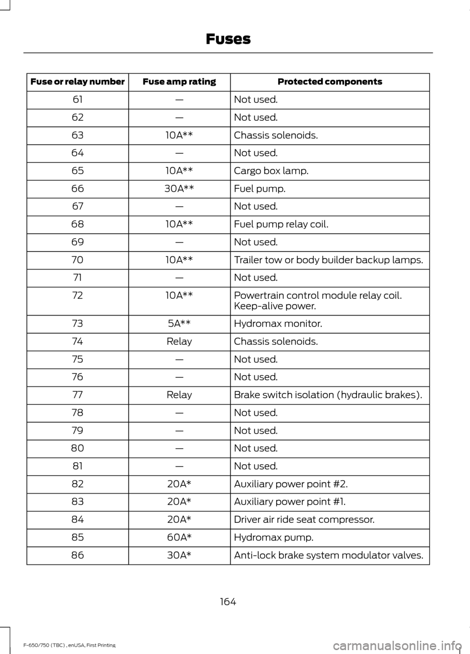
Protected components
Fuse amp rating
Fuse or relay number
Not used.
—
61
Not used.
—
62
Chassis solenoids.
10A**
63
Not used.
—
64
Cargo box lamp.
10A**
65
Fuel pump.
30A**
66
Not used.
—
67
Fuel pump relay coil.
10A**
68
Not used.
—
69
Trailer tow or body builder backup lamps.
10A**
70
Not used.
—
71
Powertrain control module relay coil.
10A**
72
Keep-alive power.
Hydromax monitor.
5A**
73
Chassis solenoids.
Relay
74
Not used.
—
75
Not used.
—
76
Brake switch isolation (hydraulic brakes).
Relay
77
Not used.
—
78
Not used.
—
79
Not used.
—
80
Not used.
—
81
Auxiliary power point #2.
20A*
82
Auxiliary power point #1.
20A*
83
Driver air ride seat compressor.
20A*
84
Hydromax pump.
60A*
85
Anti-lock brake system modulator valves.
30A*
86
164
F-650/750 (TBC) , enUSA, First Printing Fuses
Page 168 of 382
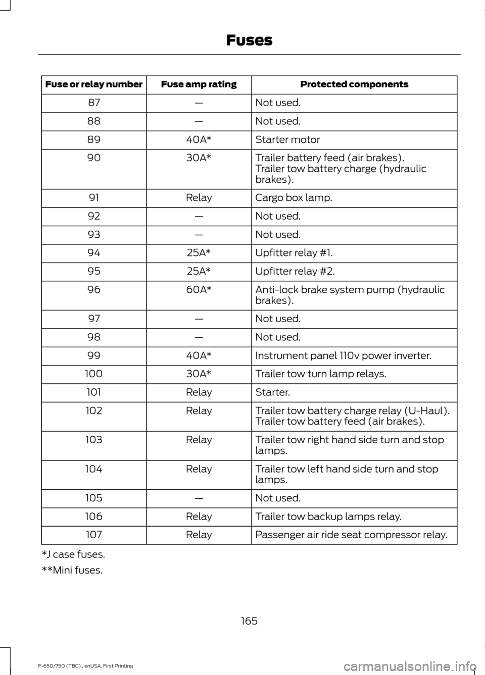
Protected components
Fuse amp rating
Fuse or relay number
Not used.
—
87
Not used.
—
88
Starter motor
40A*
89
Trailer battery feed (air brakes).
30A*
90
Trailer tow battery charge (hydraulic
brakes).
Cargo box lamp.
Relay
91
Not used.
—
92
Not used.
—
93
Upfitter relay #1.
25A*
94
Upfitter relay #2.
25A*
95
Anti-lock brake system pump (hydraulic
brakes).
60A*
96
Not used.
—
97
Not used.
—
98
Instrument panel 110v power inverter.
40A*
99
Trailer tow turn lamp relays.
30A*
100
Starter.
Relay
101
Trailer tow battery charge relay (U-Haul).
Relay
102
Trailer tow battery feed (air brakes).
Trailer tow right hand side turn and stop
lamps.
Relay
103
Trailer tow left hand side turn and stop
lamps.
Relay
104
Not used.
—
105
Trailer tow backup lamps relay.
Relay
106
Passenger air ride seat compressor relay.
Relay
107
*J case fuses.
**Mini fuses.
165
F-650/750 (TBC) , enUSA, First Printing Fuses
Page 170 of 382
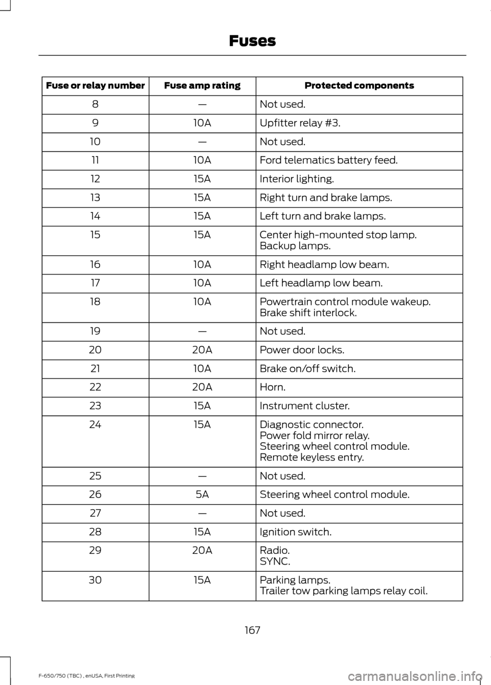
Protected components
Fuse amp rating
Fuse or relay number
Not used.
—
8
Upfitter relay #3.
10A
9
Not used.
—
10
Ford telematics battery feed.
10A
11
Interior lighting.
15A
12
Right turn and brake lamps.
15A
13
Left turn and brake lamps.
15A
14
Center high-mounted stop lamp.
15A
15
Backup lamps.
Right headlamp low beam.
10A
16
Left headlamp low beam.
10A
17
Powertrain control module wakeup.
10A
18
Brake shift interlock.
Not used.
—
19
Power door locks.
20A
20
Brake on/off switch.
10A
21
Horn.
20A
22
Instrument cluster.
15A
23
Diagnostic connector.
15A
24
Power fold mirror relay.
Steering wheel control module.
Remote keyless entry.
Not used.
—
25
Steering wheel control module.
5A
26
Not used.
—
27
Ignition switch.
15A
28
Radio.
20A
29
SYNC.
Parking lamps.
15A
30
Trailer tow parking lamps relay coil.
167
F-650/750 (TBC) , enUSA, First Printing Fuses
Page 171 of 382
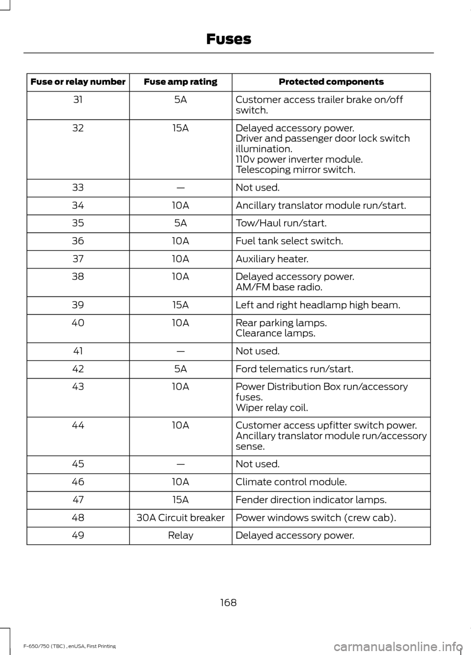
Protected components
Fuse amp rating
Fuse or relay number
Customer access trailer brake on/off
switch.
5A
31
Delayed accessory power.
15A
32
Driver and passenger door lock switch
illumination.
110v power inverter module.
Telescoping mirror switch.
Not used.
—
33
Ancillary translator module run/start.
10A
34
Tow/Haul run/start.
5A
35
Fuel tank select switch.
10A
36
Auxiliary heater.
10A
37
Delayed accessory power.
10A
38
AM/FM base radio.
Left and right headlamp high beam.
15A
39
Rear parking lamps.
10A
40
Clearance lamps.
Not used.
—
41
Ford telematics run/start.
5A
42
Power Distribution Box run/accessory
fuses.
10A
43
Wiper relay coil.
Customer access upfitter switch power.
10A
44
Ancillary translator module run/accessory
sense.
Not used.
—
45
Climate control module.
10A
46
Fender direction indicator lamps.
15A
47
Power windows switch (crew cab).
30A Circuit breaker
48
Delayed accessory power.
Relay
49
168
F-650/750 (TBC) , enUSA, First Printing Fuses
Page 176 of 382
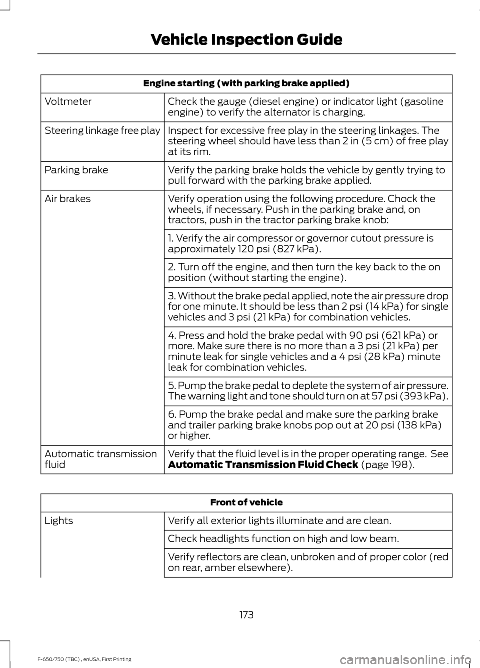
Engine starting (with parking brake applied)
Check the gauge (diesel engine) or indicator light (gasoline
engine) to verify the alternator is charging.
Voltmeter
Inspect for excessive free play in the steering linkages. The
steering wheel should have less than 2 in (5 cm) of free play
at its rim.
Steering linkage free play
Verify the parking brake holds the vehicle by gently trying to
pull forward with the parking brake applied.
Parking brake
Verify operation using the following procedure. Chock the
wheels, if necessary. Push in the parking brake and, on
tractors, push in the tractor parking brake knob:
Air brakes
1. Verify the air compressor or governor cutout pressure is
approximately 120 psi (827 kPa).
2. Turn off the engine, and then turn the key back to the on
position (without starting the engine).
3. Without the brake pedal applied, note the air pressure drop
for one minute. It should be less than 2 psi (14 kPa) for single
vehicles and
3 psi (21 kPa) for combination vehicles.
4. Press and hold the brake pedal with
90 psi (621 kPa) or
more. Make sure there is no more than a 3 psi (21 kPa) per
minute leak for single vehicles and a 4 psi (28 kPa) minute
leak for combination vehicles.
5. Pump the brake pedal to deplete the system of air pressure.
The warning light and tone should turn on at 57 psi (393 kPa).
6. Pump the brake pedal and make sure the parking brake
and trailer parking brake knobs pop out at
20 psi (138 kPa)
or higher.
Verify that the fluid level is in the proper operating range. See
Automatic Transmission Fluid Check
(page 198).
Automatic transmission
fluid Front of vehicle
Verify all exterior lights illuminate and are clean.
Lights
Check headlights function on high and low beam.
Verify reflectors are clean, unbroken and of proper color (red
on rear, amber elsewhere).
173
F-650/750 (TBC) , enUSA, First Printing Vehicle Inspection Guide
Page 181 of 382
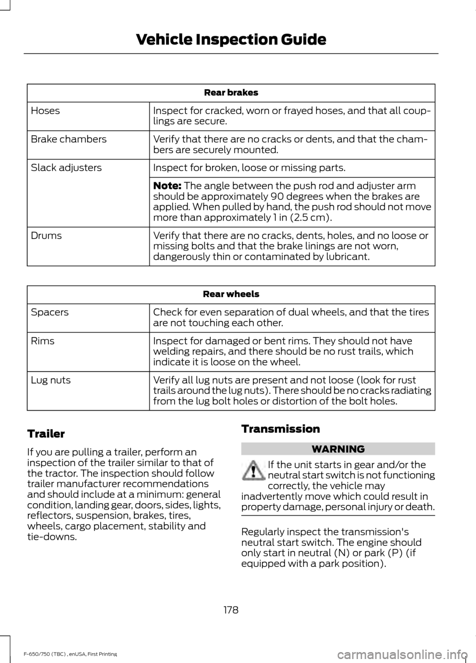
Rear brakes
Inspect for cracked, worn or frayed hoses, and that all coup-
lings are secure.
Hoses
Verify that there are no cracks or dents, and that the cham-
bers are securely mounted.
Brake chambers
Inspect for broken, loose or missing parts.
Slack adjusters
Note: The angle between the push rod and adjuster arm
should be approximately 90 degrees when the brakes are
applied. When pulled by hand, the push rod should not move
more than approximately
1 in (2.5 cm).
Verify that there are no cracks, dents, holes, and no loose or
missing bolts and that the brake linings are not worn,
dangerously thin or contaminated by lubricant.
Drums Rear wheels
Check for even separation of dual wheels, and that the tires
are not touching each other.
Spacers
Inspect for damaged or bent rims. They should not have
welding repairs, and there should be no rust trails, which
indicate it is loose on the wheel.
Rims
Verify all lug nuts are present and not loose (look for rust
trails around the lug nuts). There should be no cracks radiating
from the lug bolt holes or distortion of the bolt holes.
Lug nuts
Trailer
If you are pulling a trailer, perform an
inspection of the trailer similar to that of
the tractor. The inspection should follow
trailer manufacturer recommendations
and should include at a minimum: general
condition, landing gear, doors, sides, lights,
reflectors, suspension, brakes, tires,
wheels, cargo placement, stability and
tie-downs. Transmission WARNING
If the unit starts in gear and/or the
neutral start switch is not functioning
correctly, the vehicle may
inadvertently move which could result in
property damage, personal injury or death. Regularly inspect the transmission's
neutral start switch. The engine should
only start in neutral (N) or park (P) (if
equipped with a park position).
178
F-650/750 (TBC) , enUSA, First Printing Vehicle Inspection Guide