tow FORD F650 2017 13.G Service Manual
[x] Cancel search | Manufacturer: FORD, Model Year: 2017, Model line: F650, Model: FORD F650 2017 13.GPages: 382, PDF Size: 5.18 MB
Page 168 of 382
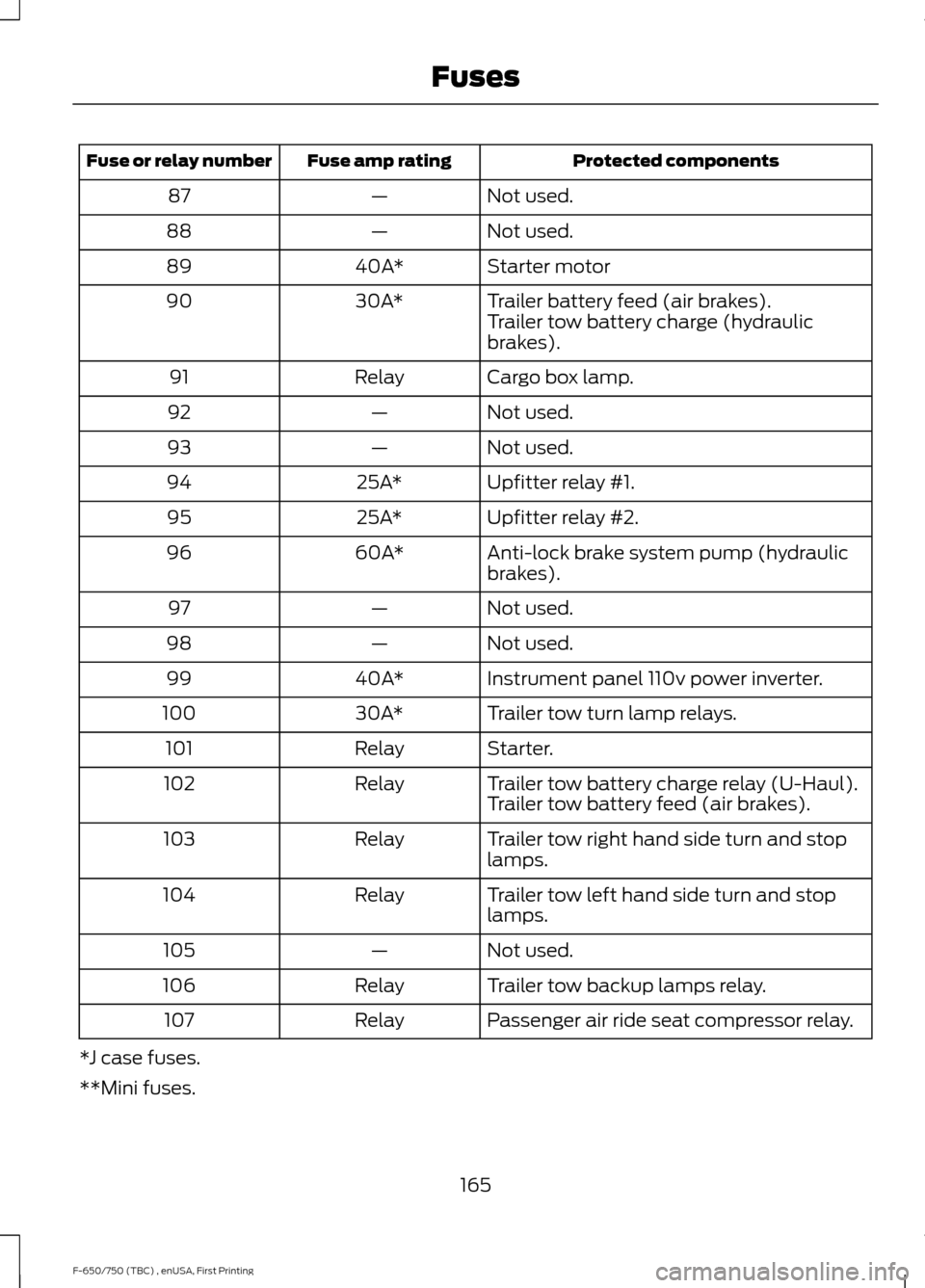
Protected components
Fuse amp rating
Fuse or relay number
Not used.
—
87
Not used.
—
88
Starter motor
40A*
89
Trailer battery feed (air brakes).
30A*
90
Trailer tow battery charge (hydraulic
brakes).
Cargo box lamp.
Relay
91
Not used.
—
92
Not used.
—
93
Upfitter relay #1.
25A*
94
Upfitter relay #2.
25A*
95
Anti-lock brake system pump (hydraulic
brakes).
60A*
96
Not used.
—
97
Not used.
—
98
Instrument panel 110v power inverter.
40A*
99
Trailer tow turn lamp relays.
30A*
100
Starter.
Relay
101
Trailer tow battery charge relay (U-Haul).
Relay
102
Trailer tow battery feed (air brakes).
Trailer tow right hand side turn and stop
lamps.
Relay
103
Trailer tow left hand side turn and stop
lamps.
Relay
104
Not used.
—
105
Trailer tow backup lamps relay.
Relay
106
Passenger air ride seat compressor relay.
Relay
107
*J case fuses.
**Mini fuses.
165
F-650/750 (TBC) , enUSA, First Printing Fuses
Page 169 of 382
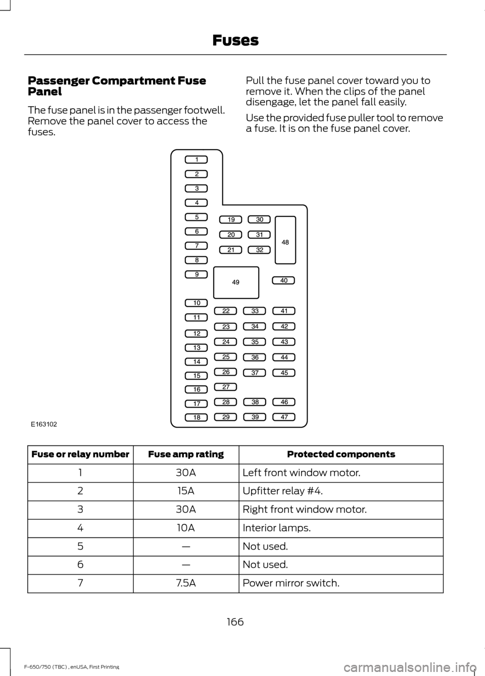
Passenger Compartment Fuse
Panel
The fuse panel is in the passenger footwell.
Remove the panel cover to access the
fuses.
Pull the fuse panel cover toward you to
remove it. When the clips of the panel
disengage, let the panel fall easily.
Use the provided fuse puller tool to remove
a fuse. It is on the fuse panel cover. Protected components
Fuse amp rating
Fuse or relay number
Left front window motor.
30A
1
Upfitter relay #4.
15A
2
Right front window motor.
30A
3
Interior lamps.
10A
4
Not used.
—
5
Not used.
—
6
Power mirror switch.
7.5A
7
166
F-650/750 (TBC) , enUSA, First Printing FusesE163102
Page 170 of 382
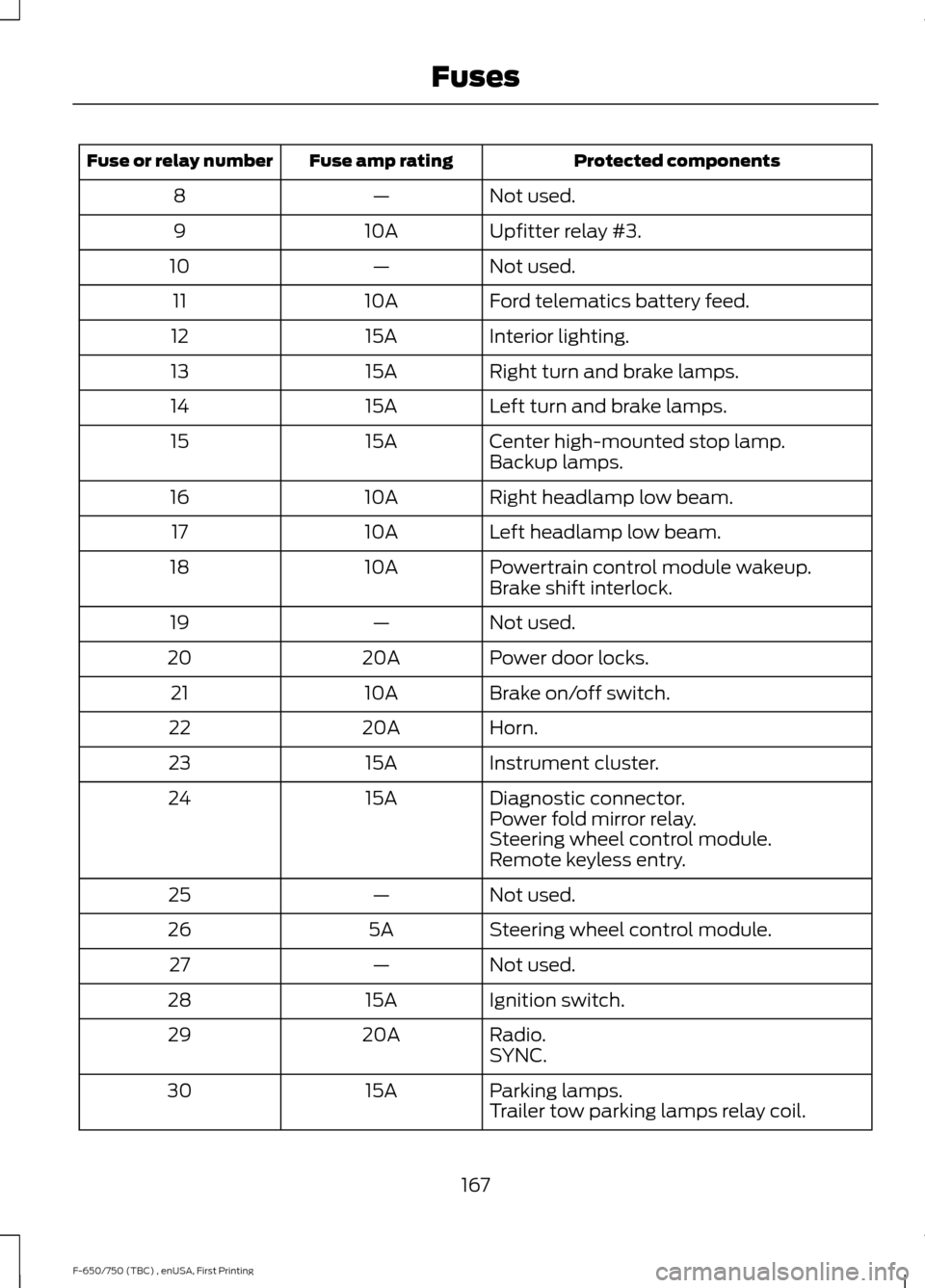
Protected components
Fuse amp rating
Fuse or relay number
Not used.
—
8
Upfitter relay #3.
10A
9
Not used.
—
10
Ford telematics battery feed.
10A
11
Interior lighting.
15A
12
Right turn and brake lamps.
15A
13
Left turn and brake lamps.
15A
14
Center high-mounted stop lamp.
15A
15
Backup lamps.
Right headlamp low beam.
10A
16
Left headlamp low beam.
10A
17
Powertrain control module wakeup.
10A
18
Brake shift interlock.
Not used.
—
19
Power door locks.
20A
20
Brake on/off switch.
10A
21
Horn.
20A
22
Instrument cluster.
15A
23
Diagnostic connector.
15A
24
Power fold mirror relay.
Steering wheel control module.
Remote keyless entry.
Not used.
—
25
Steering wheel control module.
5A
26
Not used.
—
27
Ignition switch.
15A
28
Radio.
20A
29
SYNC.
Parking lamps.
15A
30
Trailer tow parking lamps relay coil.
167
F-650/750 (TBC) , enUSA, First Printing Fuses
Page 171 of 382
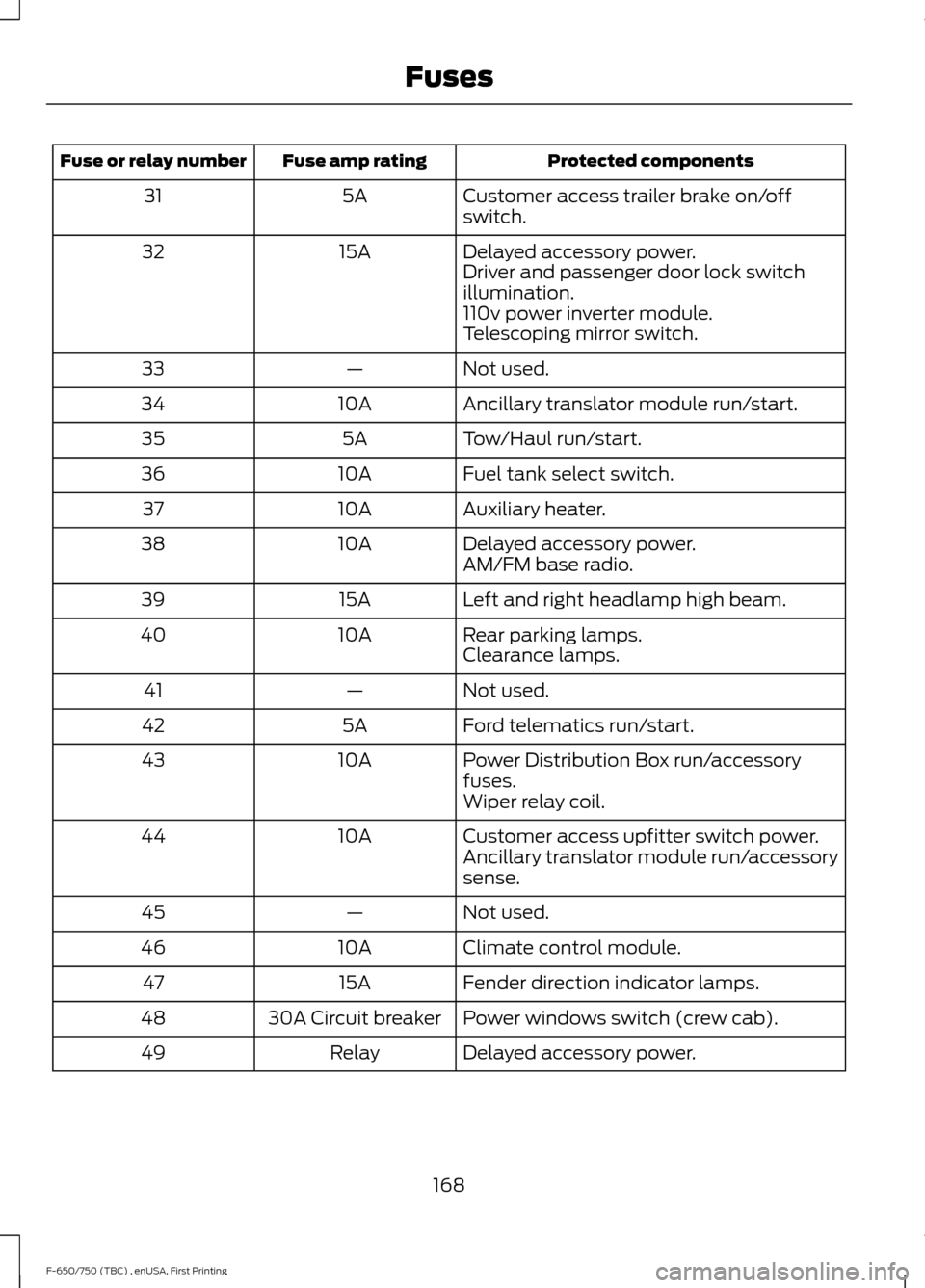
Protected components
Fuse amp rating
Fuse or relay number
Customer access trailer brake on/off
switch.
5A
31
Delayed accessory power.
15A
32
Driver and passenger door lock switch
illumination.
110v power inverter module.
Telescoping mirror switch.
Not used.
—
33
Ancillary translator module run/start.
10A
34
Tow/Haul run/start.
5A
35
Fuel tank select switch.
10A
36
Auxiliary heater.
10A
37
Delayed accessory power.
10A
38
AM/FM base radio.
Left and right headlamp high beam.
15A
39
Rear parking lamps.
10A
40
Clearance lamps.
Not used.
—
41
Ford telematics run/start.
5A
42
Power Distribution Box run/accessory
fuses.
10A
43
Wiper relay coil.
Customer access upfitter switch power.
10A
44
Ancillary translator module run/accessory
sense.
Not used.
—
45
Climate control module.
10A
46
Fender direction indicator lamps.
15A
47
Power windows switch (crew cab).
30A Circuit breaker
48
Delayed accessory power.
Relay
49
168
F-650/750 (TBC) , enUSA, First Printing Fuses
Page 177 of 382
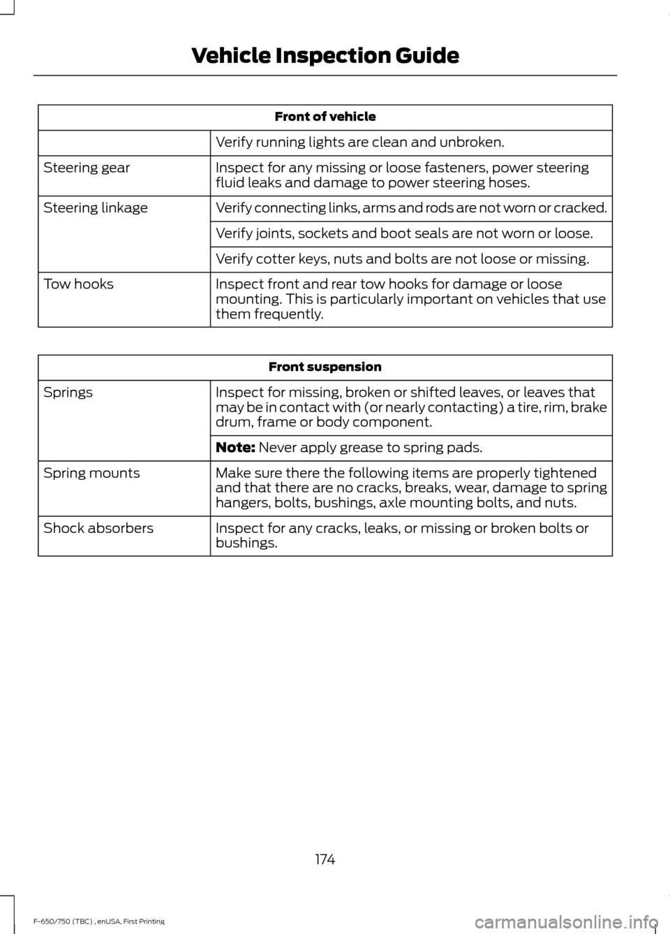
Front of vehicle
Verify running lights are clean and unbroken.
Inspect for any missing or loose fasteners, power steering
fluid leaks and damage to power steering hoses.
Steering gear
Verify connecting links, arms and rods are not worn or cracked.
Steering linkage
Verify joints, sockets and boot seals are not worn or loose.
Verify cotter keys, nuts and bolts are not loose or missing.
Inspect front and rear tow hooks for damage or loose
mounting. This is particularly important on vehicles that use
them frequently.
Tow hooks Front suspension
Inspect for missing, broken or shifted leaves, or leaves that
may be in contact with (or nearly contacting) a tire, rim, brake
drum, frame or body component.
Springs
Note: Never apply grease to spring pads.
Make sure there the following items are properly tightened
and that there are no cracks, breaks, wear, damage to spring
hangers, bolts, bushings, axle mounting bolts, and nuts.
Spring mounts
Inspect for any cracks, leaks, or missing or broken bolts or
bushings.
Shock absorbers
174
F-650/750 (TBC) , enUSA, First Printing Vehicle Inspection Guide
Page 191 of 382
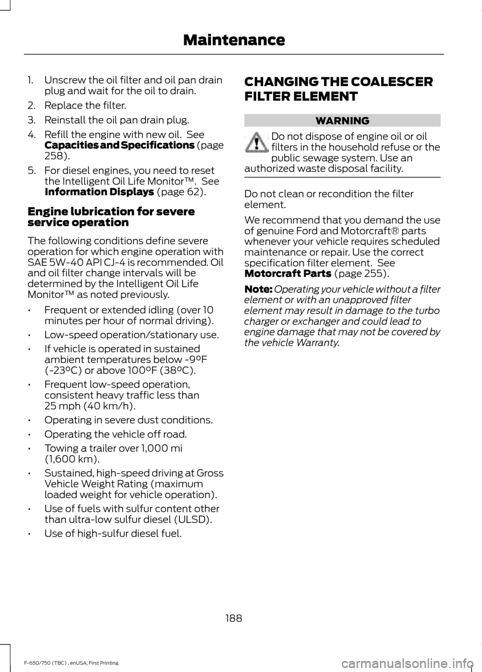
1. Unscrew the oil filter and oil pan drain
plug and wait for the oil to drain.
2. Replace the filter.
3. Reinstall the oil pan drain plug.
4. Refill the engine with new oil. See Capacities and Specifications (page
258).
5. For diesel engines, you need to reset the Intelligent Oil Life Monitor™. See
Information Displays
(page 62).
Engine lubrication for severe
service operation
The following conditions define severe
operation for which engine operation with
SAE 5W-40 API CJ-4 is recommended. Oil
and oil filter change intervals will be
determined by the Intelligent Oil Life
Monitor™ as noted previously.
• Frequent or extended idling (over 10
minutes per hour of normal driving).
• Low-speed operation/stationary use.
• If vehicle is operated in sustained
ambient temperatures below
-9°F
(-23°C) or above 100°F (38°C).
• Frequent low-speed operation,
consistent heavy traffic less than
25 mph (40 km/h)
.
• Operating in severe dust conditions.
• Operating the vehicle off road.
• Towing a trailer over
1,000 mi
(1,600 km).
• Sustained, high-speed driving at Gross
Vehicle Weight Rating (maximum
loaded weight for vehicle operation).
• Use of fuels with sulfur content other
than ultra-low sulfur diesel (ULSD).
• Use of high-sulfur diesel fuel. CHANGING THE COALESCER
FILTER ELEMENT WARNING
Do not dispose of engine oil or oil
filters in the household refuse or the
public sewage system. Use an
authorized waste disposal facility. Do not clean or recondition the filter
element.
We recommend that you demand the use
of genuine Ford and Motorcraft® parts
whenever your vehicle requires scheduled
maintenance or repair. Use the correct
specification filter element. See
Motorcraft Parts
(page 255).
Note: Operating your vehicle without a filter
element or with an unapproved filter
element may result in damage to the turbo
charger or exchanger and could lead to
engine damage that may not be covered by
the vehicle Warranty.
188
F-650/750 (TBC) , enUSA, First Printing Maintenance
Page 195 of 382
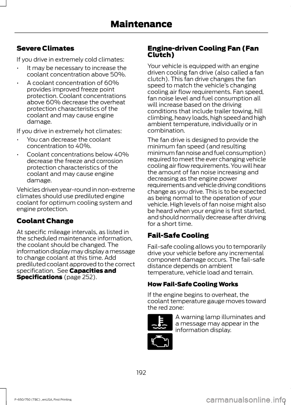
Severe Climates
If you drive in extremely cold climates:
•
It may be necessary to increase the
coolant concentration above 50%.
• A coolant concentration of 60%
provides improved freeze point
protection. Coolant concentrations
above 60% decrease the overheat
protection characteristics of the
coolant and may cause engine
damage.
If you drive in extremely hot climates:
• You can decrease the coolant
concentration to 40%.
• Coolant concentrations below 40%
decrease the freeze and corrosion
protection characteristics of the
coolant and may cause engine
damage.
Vehicles driven year-round in non-extreme
climates should use prediluted engine
coolant for optimum cooling system and
engine protection.
Coolant Change
At specific mileage intervals, as listed in
the scheduled maintenance information,
the coolant should be changed. The
information display may display a message
to change coolant at this time. Add
prediluted coolant approved to the correct
specification. See Capacities and
Specifications (page 252). Engine-driven Cooling Fan (Fan
Clutch)
Your vehicle is equipped with an engine
driven cooling fan drive (also called a fan
clutch). This fan drive changes the fan
speed to match the vehicle
’s changing
cooling air flow requirements. Fan speed,
fan noise level and fuel consumption all
will increase based on the driving
conditions that include trailer towing, hill
climbing, heavy loads, high speed and high
ambient temperature, individually or in
combination.
The fan drive is designed to provide the
minimum fan speed (and resulting
minimum fan noise and fuel consumption)
required to meet the ever changing vehicle
cooling air flow requirements. You will hear
the amount of fan noise increasing and
decreasing as the engine power
requirements and vehicle driving conditions
change as you drive. This is to be expected
as being normal to the operation of your
vehicle. High levels of fan noise might also
be heard when your engine is first started,
and should normally decrease after driving
for a short time.
Fail-Safe Cooling
Fail-safe cooling allows you to temporarily
drive your vehicle before any incremental
component damage occurs. The fail-safe
distance depends on ambient
temperature, vehicle load and terrain.
How Fail-Safe Cooling Works
If the engine begins to overheat, the
coolant temperature gauge moves toward
the red zone: A warning lamp illuminates and
a message may appear in the
information display.
192
F-650/750 (TBC) , enUSA, First Printing Maintenance
Page 196 of 382
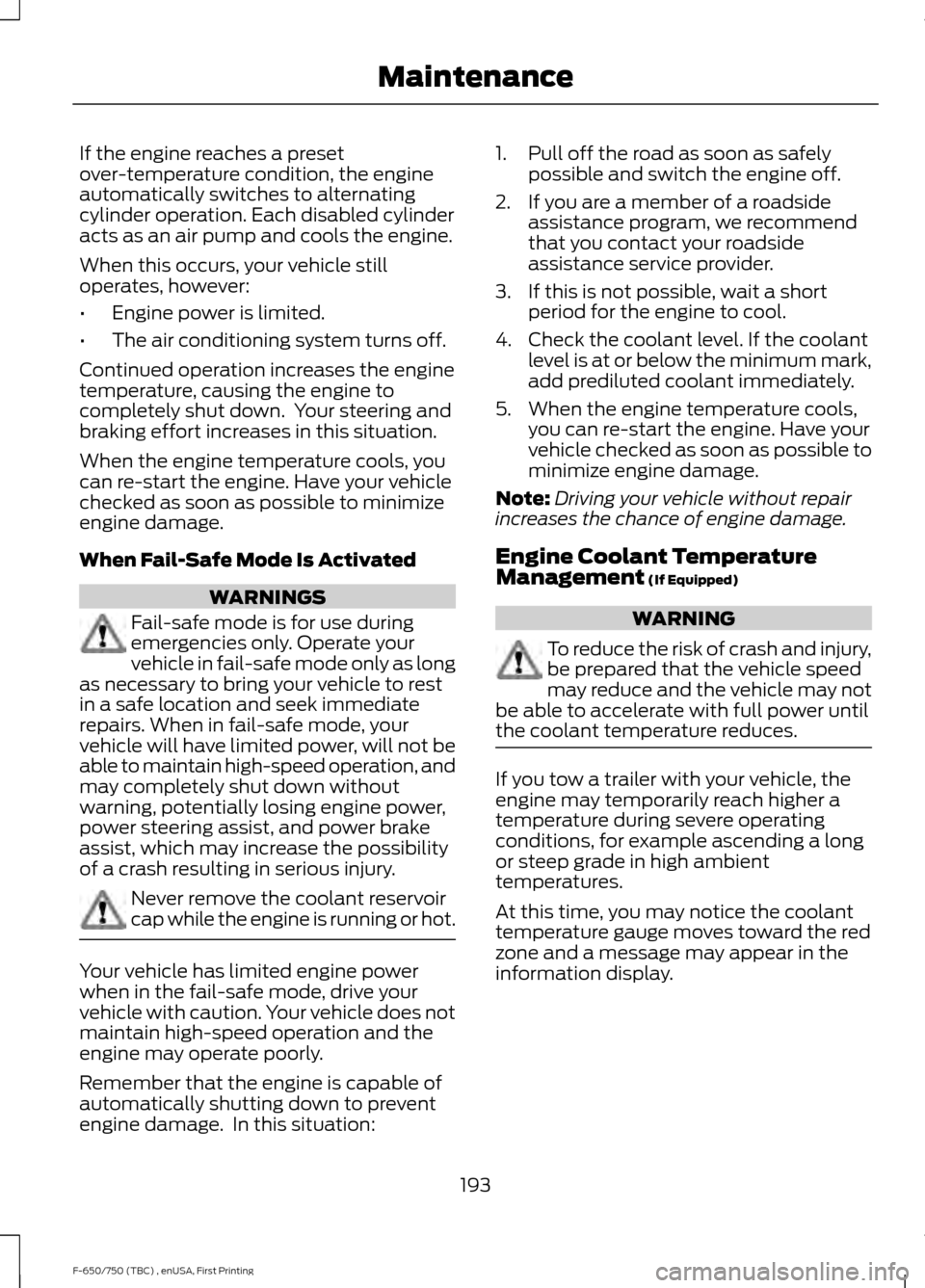
If the engine reaches a preset
over-temperature condition, the engine
automatically switches to alternating
cylinder operation. Each disabled cylinder
acts as an air pump and cools the engine.
When this occurs, your vehicle still
operates, however:
•
Engine power is limited.
• The air conditioning system turns off.
Continued operation increases the engine
temperature, causing the engine to
completely shut down. Your steering and
braking effort increases in this situation.
When the engine temperature cools, you
can re-start the engine. Have your vehicle
checked as soon as possible to minimize
engine damage.
When Fail-Safe Mode Is Activated WARNINGS
Fail-safe mode is for use during
emergencies only. Operate your
vehicle in fail-safe mode only as long
as necessary to bring your vehicle to rest
in a safe location and seek immediate
repairs. When in fail-safe mode, your
vehicle will have limited power, will not be
able to maintain high-speed operation, and
may completely shut down without
warning, potentially losing engine power,
power steering assist, and power brake
assist, which may increase the possibility
of a crash resulting in serious injury. Never remove the coolant reservoir
cap while the engine is running or hot.
Your vehicle has limited engine power
when in the fail-safe mode, drive your
vehicle with caution. Your vehicle does not
maintain high-speed operation and the
engine may operate poorly.
Remember that the engine is capable of
automatically shutting down to prevent
engine damage. In this situation: 1. Pull off the road as soon as safely
possible and switch the engine off.
2. If you are a member of a roadside assistance program, we recommend
that you contact your roadside
assistance service provider.
3. If this is not possible, wait a short period for the engine to cool.
4. Check the coolant level. If the coolant level is at or below the minimum mark,
add prediluted coolant immediately.
5. When the engine temperature cools, you can re-start the engine. Have your
vehicle checked as soon as possible to
minimize engine damage.
Note: Driving your vehicle without repair
increases the chance of engine damage.
Engine Coolant Temperature
Management (If Equipped) WARNING
To reduce the risk of crash and injury,
be prepared that the vehicle speed
may reduce and the vehicle may not
be able to accelerate with full power until
the coolant temperature reduces. If you tow a trailer with your vehicle, the
engine may temporarily reach higher a
temperature during severe operating
conditions, for example ascending a long
or steep grade in high ambient
temperatures.
At this time, you may notice the coolant
temperature gauge moves toward the red
zone and a message may appear in the
information display.
193
F-650/750 (TBC) , enUSA, First Printing Maintenance
Page 201 of 382
•
Robinair® Coolant and Battery
Refractometer 75240 –
Recommended refractometer to test
coolant concentration. (Rotunda tool
part number: ROB75240).
• Rotunda 328-R071–ELC (Antifreeze
Coolant ELC Contamination Kit)
–
Evaluates the corrosion inhibitor
additive strength. Note the first step is
to verify the vehicle ’s coolant
concentration is in the correct range of
40 – 60%. Coolant concentrations
outside this range will not provide valid
test results. If the report results in a
pass, for example the cooling system
does not show excessive
contamination, the corrosion inhibitor
additive strength is sufficient, and no
action is required. If the report results
as insufficient (does not pass), the
corrosion inhibitor additive strength of
the coolant is too low. If the engine
cooling system corrosion inhibitor
additive strength is low, add
47 fl oz
(1.4 L) of Motorcraft Specialty Orange
Engine Coolant Revitalizer. If the
secondary cooling system corrosion
inhibitor additive strength is low, add
16 fl oz (0.47 L) of Motorcraft Specialty
Orange Engine Coolant Revitalizer.
• Motorcraft Specialty Orange Engine
Coolant Revitalizer
– Additive to
boost the corrosion inhibitor level
based upon the test results of the
Antifreeze Coolant ELC Contamination
Kit. The Revitalizer may be added two
times over the life of the coolant. If
additional dosages are required, the
cooling system must be flushed and
refilled per the instructions in the
Workshop Manual.
Make sure to follow the proper coolant and
additive specifications. See
Capacities
and Specifications (page 252). Coolant Change
At specific mileage intervals, as listed in
the scheduled maintenance information,
the coolant should be changed. The
information display may display a message
to change coolant at this time. Add
prediluted coolant approved to the correct
specification. See
Capacities and
Specifications (page 252).
Engine-driven Cooling Fan (Fan
Clutch)
Your vehicle may have an engine driven
cooling fan drive (also called a fan clutch).
This fan drive changes the fan speed to
match the vehicle ’s changing cooling air
flow requirements. Fan speed, fan noise
level and fuel consumption all will increase
based on the driving conditions that
include trailer towing, hill climbing, heavy
loads, high speed and high ambient
temperature, individually or in combination.
The fan drive is designed to provide the
minimum fan speed (and resulting
minimum fan noise and fuel consumption)
required to meet the ever changing vehicle
cooling air flow requirements. You will hear
the amount of fan noise increasing and
decreasing as the engine power
requirements and vehicle driving conditions
change as you drive. This is to be expected
as being normal to the operation of your
vehicle. High levels of fan noise might also
be heard when your engine is first started,
and should normally decrease after driving
for a short time.
AUTOMATIC TRANSMISSION
FLUID CHECK
The transmission does not consume fluid.
However, the fluid level should be checked
if the transmission is not working properly,
for example if the transmission slips, shifts
slowly or if there are signs of fluid loss.
198
F-650/750 (TBC) , enUSA, First Printing Maintenance
Page 213 of 382
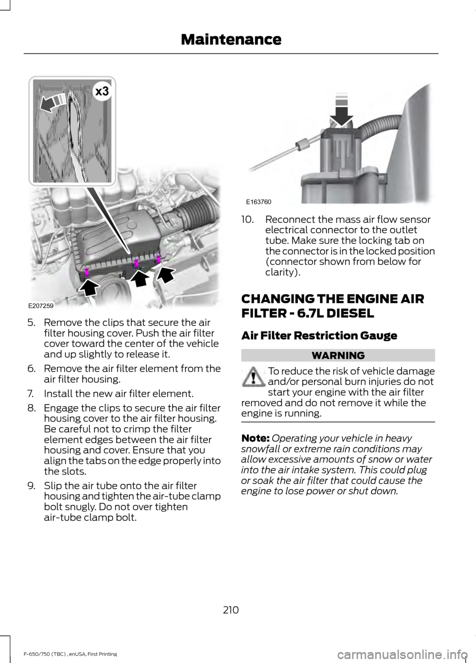
5. Remove the clips that secure the air
filter housing cover. Push the air filter
cover toward the center of the vehicle
and up slightly to release it.
6. Remove the air filter element from the
air filter housing.
7. Install the new air filter element.
8. Engage the clips to secure the air filter housing cover to the air filter housing.
Be careful not to crimp the filter
element edges between the air filter
housing and cover. Ensure that you
align the tabs on the edge properly into
the slots.
9. Slip the air tube onto the air filter housing and tighten the air-tube clamp
bolt snugly. Do not over tighten
air-tube clamp bolt. 10. Reconnect the mass air flow sensor
electrical connector to the outlet
tube. Make sure the locking tab on
the connector is in the locked position
(connector shown from below for
clarity).
CHANGING THE ENGINE AIR
FILTER - 6.7L DIESEL
Air Filter Restriction Gauge WARNING
To reduce the risk of vehicle damage
and/or personal burn injuries do not
start your engine with the air filter
removed and do not remove it while the
engine is running. Note:
Operating your vehicle in heavy
snowfall or extreme rain conditions may
allow excessive amounts of snow or water
into the air intake system. This could plug
or soak the air filter that could cause the
engine to lose power or shut down.
210
F-650/750 (TBC) , enUSA, First Printing MaintenanceE207259
x3 E163760