engine FORD F650 2017 13.G Repair Manual
[x] Cancel search | Manufacturer: FORD, Model Year: 2017, Model line: F650, Model: FORD F650 2017 13.GPages: 382, PDF Size: 5.18 MB
Page 127 of 382
When air pressure is insufficient
(below 60 psi (414 kPa)), a
warning light illuminates and a
buzzer sounds when the ignition is in the
on position. This may happen because
excessive brake applications are depleting
the system air pressure. If this condition
occurs, stop driving your vehicle until the
compressor has fully recharged the air
system.
Select a gear ratio to help slow your vehicle
before descending grades. Supplementing
with brakes, as required, help to safely slow
the vehicle and avoids overspeeding the
engine.
Air Chamber Stroke Indication
Air chamber push rods have orange stroke
indicator markers that warn when the
braking system requires adjustment or
repair. The painted orange indicator is on
the air chamber push rod at the slack
adjuster stroke dimension that requires
service when visible during brake
application.
A qualified service technician should
perform air brake inspection and
adjustment or repairs keeping to the
instructions in the service manual.
Cam Brakes - Automatic Slack
Adjusters WARNING
Do not manually adjust the
automatic slack adjusters to correct
excessive push rod stroke as it may
result in reduced brake effectiveness and
a vehicle crash. Excessive push rod stroke
indicates that a problem exists with the
automatic adjuster, with the installation
of the adjuster, or with foundation brake
components that manual adjustment does
not remedy. Seek service from a qualified
facility for excessive push rod stroke. Standard air brakes (cam) are equipped
with automatic brake adjusters. Automatic
adjustment occurs during brake
applications. Inspect brakes for proper
adjustment at the specified intervals. See
Scheduled Maintenance
(page 316).
Emergency Air Brake WARNING
Do not continue to operate the
vehicle with a failure of one of the
brake systems. Take the vehicle to
your dealer for service immediately. All vehicles are equipped with a dual brake
system. In the unlikely event of a failure of
one system, the second system functions
for emergency stopping. The brake pedal
controls all these systems in the same
manner as for normal stops.
EXHAUST BRAKE
WARNING
The exhaust brake is not
recommended for use on slippery or
low traction road surfaces. Under
these conditions a loss of vehicle control
could occur. 124
F-650/750 (TBC) , enUSA, First Printing BrakesE206772 E210337
Page 128 of 382
Note:
Installing an exhaust or auxiliary
brake does not necessarily protect the
engine from exceeding maximum governed
speed. Use the primary brakes to make sure
the engine never exceeds maximum
governed speed under any circumstance.
Note: Before starting the engine, make sure
that the exhaust brake switch is in the off
position. Do not turn the exhaust brake on
until the engine has reached normal
operating temperature.
Note: Maximum exhaust brake
performance relates to the type of
transmission your vehicle has.
Note: Engine speed has a major influence
of retarding performance. When engine
speed stays at the maximum allowable
level, the exhaust brake operates at peak
performance.
Note: Exhaust brakes operate effectively
with automatic transmissions, but
performance varies with engine speed and
the gear selected by the transmission.
An exhaust brake is an auxiliary braking
system that assists, but does not replace,
the primary service brake system. It helps
control vehicle speed; it is not a
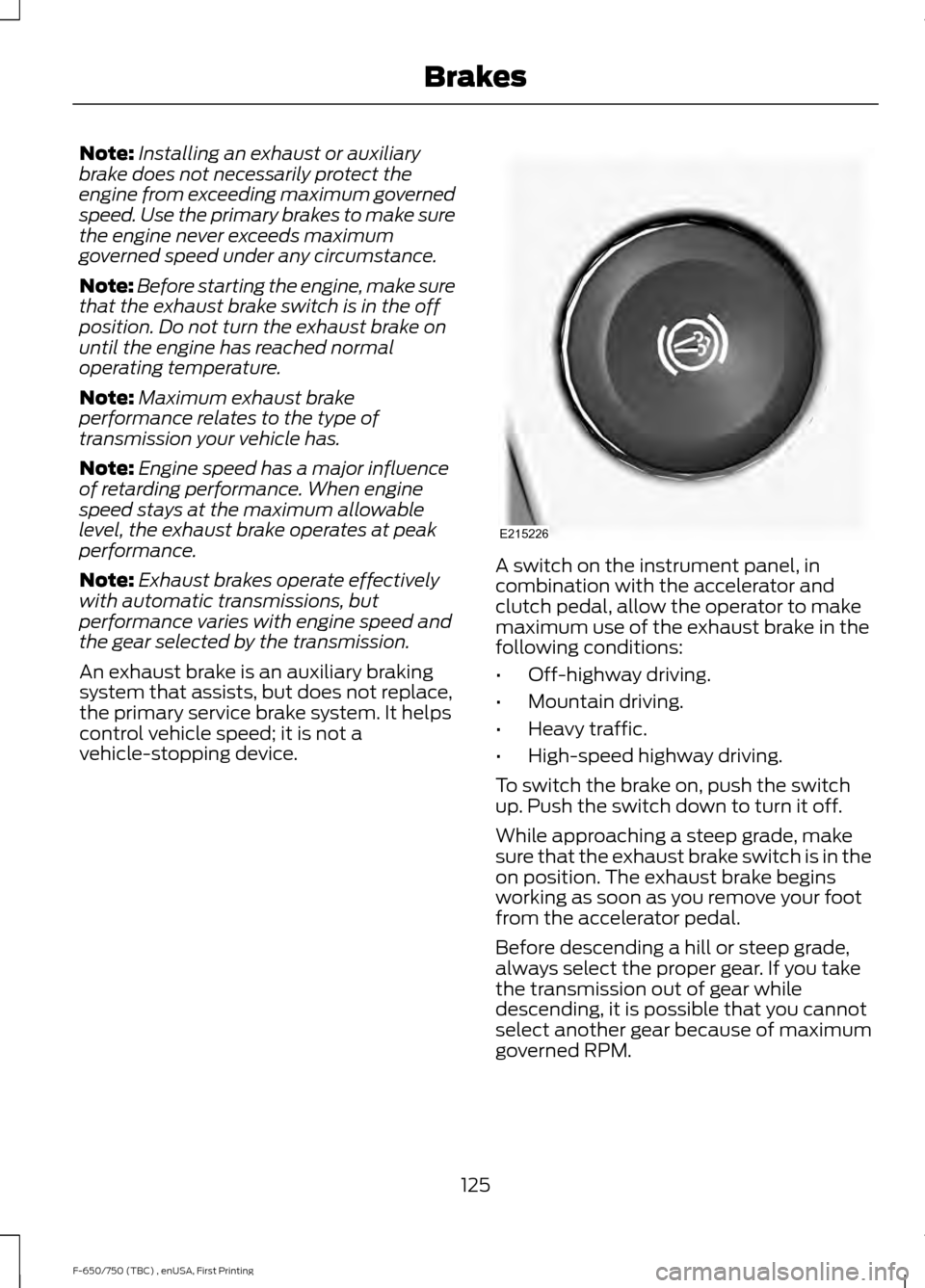
vehicle-stopping device. A switch on the instrument panel, in
combination with the accelerator and
clutch pedal, allow the operator to make
maximum use of the exhaust brake in the
following conditions:
•
Off-highway driving.
• Mountain driving.
• Heavy traffic.
• High-speed highway driving.
To switch the brake on, push the switch
up. Push the switch down to turn it off.
While approaching a steep grade, make
sure that the exhaust brake switch is in the
on position. The exhaust brake begins
working as soon as you remove your foot
from the accelerator pedal.
Before descending a hill or steep grade,
always select the proper gear. If you take
the transmission out of gear while
descending, it is possible that you cannot
select another gear because of maximum
governed RPM.
125
F-650/750 (TBC) , enUSA, First Printing BrakesE215226
Page 129 of 382
Make sure the engine speed does not
exceed the maximum allowable engine
RPM. Exceeding the maximum allowable
engine RPM can result in damage to the
engine. Apply the service brakes to reduce
the engine RPM or make a slower descent
by using a lower gear.
While going down the grade, use a low
enough gear to descend safely with a
minimum application of the service brakes.
As a general guideline, use the same gear
as you use to ascend the hill.
Exhaust Brake Operating
Characteristics
The exhaust brake turns on when you
remove your feet from both the accelerator
and clutch pedals and the exhaust brake
switch is in the on position. The following
conditions exist if the brake is operating
properly:
•
A slight change in engine sound when
the exhaust brake turns on.
• A smooth braking effect. Do not expect
a retarding effect similar to sudden,
hard application of the service brakes.
• The retarding force possibly felt acting
against your body during brake
application (depending on the grade
and vehicle load). This force is actually
preventing the vehicle from going much
faster.
• Engine temperature remaining in the
normal operating range.
• The tachometer showing a drop in
engine RPM (depending on grade and
vehicle load) during a descent.
• A decrease in road speed when
applying the exhaust brake during a
descent, except when your vehicle is
carrying a heavy load or the grade is
extremely steep. In these instances,
you may need to apply the service
brakes occasionally. TRAILER BRAKES
Trailer Brake Hand Control (If Equipped) WARNING
The hand control should never be
used to apply the brakes when the
tractor and trailer are parked
unattended. Air may leak from the system
and the vehicle could possibly move,
resulting in possible property damage,
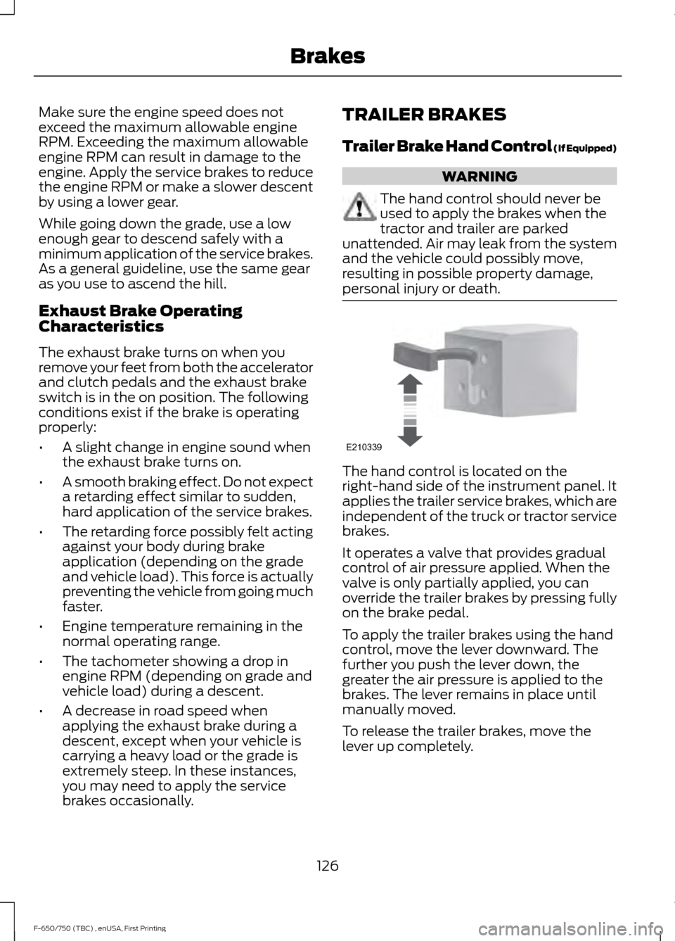
personal injury or death. The hand control is located on the
right-hand side of the instrument panel. It
applies the trailer service brakes, which are
independent of the truck or tractor service
brakes.
It operates a valve that provides gradual
control of air pressure applied. When the
valve is only partially applied, you can
override the trailer brakes by pressing fully
on the brake pedal.
To apply the trailer brakes using the hand
control, move the lever downward. The
further you push the lever down, the
greater the air pressure is applied to the
brakes. The lever remains in place until
manually moved.
To release the trailer brakes, move the
lever up completely.
126
F-650/750 (TBC) , enUSA, First Printing BrakesE210339
Page 133 of 382
PRINCIPLE OF OPERATION
The traction control system helps avoid
drive wheel spin and loss of traction.
If your vehicle begins to slide, the system
applies the brakes to individual wheels
and, when needed, reduces engine power
at the same time. If the wheels spin when
accelerating on slippery or loose surfaces,
the system reduces engine power in order
to increase traction.
Note:
The system does not apply the brakes
when vehicle speed is above 25 mph
(40 km/h).
USING TRACTION CONTROL -
VEHICLES WITH: AIR BRAKES WARNING
Aggressive driving in any road
conditions can cause you to lose
control of your vehicle increasing the
risk of severe personal injury or property
damage. The occurrence of a traction
control event is an indication that at least
some of the tires have exceeded their
ability to grip the road; this may lead to an
increased risk of loss of vehicle control,
vehicle rollover, personal injury and death.
If you experience a severe road event,
SLOW DOWN. Use the traction control switch on the
instrument panel to select Off Road or
Mud/Snow traction mode.
This is beneficial when your vehicle is stuck
in snow or on a slippery road surface. This
mode allows excess wheel spin to dig your
vehicle out and allows you to rock your
vehicle.
Press the switch again to select standard
traction control. The system automatically
selects standard traction control at the
next ignition cycle. System Indicator Light
Note:
If the traction control light does not
flash during a traction control event or stays
illuminated, the system is not functioning
properly. Take your vehicle to an authorized
dealer for service.
During traction control operation, the
traction control light flashes rapidly and
the engine does not rev-up when you press
further on the accelerator. This is normal
and is no reason for concern.
In Off Road or Mud/Snow mode, the
traction control light illuminates and
flashes slowly. If a traction event occurs in
either mode, the light flashes rapidly.
USING TRACTION CONTROL -
VEHICLES WITH: HYDRAULIC
BRAKES WARNING
Aggressive driving in any road
conditions can cause you to lose
control of your vehicle increasing the
risk of severe personal injury or property
damage. The occurrence of a traction
control event is an indication that at least
some of the tires have exceeded their
ability to grip the road; this may lead to an
increased risk of loss of vehicle control,
vehicle rollover, personal injury and death.
If you experience a severe road event,
SLOW DOWN. The system automatically turns on each
time you switch the ignition on.
Use the traction control switch on the
instrument panel to switch the system off
or on.
If your vehicle is stuck in mud or snow,
switching traction control off may be
beneficial as this allows the wheels to spin.
130
F-650/750 (TBC) , enUSA, First Printing Traction Control
Page 134 of 382
Press the switch again to enable the
traction control system.
System Indicator Light
Note:
If the traction control light does not
flash during a traction control event or stays
illuminated, the system is not functioning
properly. Take your vehicle to an authorized
dealer for service.
During traction control operation, the
traction control light flashes rapidly and
the engine does not rev-up when you press
further on the accelerator. This is normal
and is no reason for concern.
When traction control is disabled, the
traction control light illuminates and
flashes slowly.
131
F-650/750 (TBC) , enUSA, First Printing Traction Control
Page 137 of 382
STEERING
To help prevent damage to the power
steering system:
•
Never hold the steering wheel at its
furthest turning points (until it stops)
for more than three to five seconds
when the engine is running.
• Do not operate the vehicle with a low
power steering pump fluid level (below
the MIN mark on the reservoir).
• Some noise is normal during operation.
If excessive, check for low power
steering pump fluid level before
seeking service by your dealer.
• Heavy or uneven efforts may be caused
by low power steering fluid. Check for
low power steering pump fluid level
before seeking service by your dealer.
• Do not fill the power steering pump
reservoir above the MAX mark on the
reservoir, as this may result in leaks
from the reservoir.
If the power steering system breaks down
(or if the engine is turned off), you can
steer the vehicle manually, but it takes
more effort.
Operating the steering system excessively
at an elevated engine RPM (>1200 rpm)
for more than 2 minutes can result in
steering system damage from overheating.
Move the steering wheel to the full left
position then full right position at idle
speed, or stop using the system for 2
minutes to allow the system to cool down.
If the power steering system exhibits heavy
or uneven efforts, check for the following
before seeking service from your dealer:
• An improperly inflated tire.
• Overloading of front suspension.
• Uneven vehicle loading.
• Binding suspension components. If the power steering system wanders or
pulls, check for:
•
An improperly inflated tire.
• Uneven vehicle loading.
• Uneven tire wear.
• Loose or worn suspension
components.
• Loose or worn steering components.
• Improper vehicle alignment.
• High crosswinds.
If any steering components are serviced or
replaced, install new fasteners (many are
coated with thread adhesive or have
prevailing torque features which may not
be re-used). Never re-use a bolt or nut.
Torque fasteners to specifications.
A high crown in the road or high crosswinds
may also make the steering seem to
wander or pull.
134
F-650/750 (TBC) , enUSA, First Printing Driving Aids
Page 141 of 382
TOWING A TRAILER
WARNINGS
Do not exceed the GVWR or
the GAWR specified on the
certification label. Towing trailers beyond the
maximum recommended
gross trailer weight exceeds the
limit of the vehicle and could
result in engine damage,
transmission damage, structural
damage, loss of vehicle control,
vehicle rollover and personal
injury. Your vehicle may have electrical
items, such as fuses or relays,
related to towing. See Fuses
(page 161).
Your vehicle's load capacity
designation is by weight, not by
volume, so you cannot necessarily
use all available space when
loading a vehicle.
Towing a trailer places an extra
load on your vehicle's engine,
transmission, axle, brakes, tires
and suspension. Inspect these
components periodically during,
and after, any towing operation. Load Placement
To help minimize how trailer
movement affects your vehicle
when driving:
•
Load the heaviest items closest
to the trailer floor.
• Load the heaviest items
centered between the left and
right side trailer tires.
• Load the heaviest items above
the trailer axles or just slightly
forward toward the trailer
tongue. Do not allow the final
trailer tongue weight to go
above or below 10-15% of the
loaded trailer weight.
When driving with a trailer or
payload, a slight takeoff vibration
or shudder may be present due to
the increased payload weight.
Additional information regarding
proper trailer loading and setting
your vehicle up for towing is
located in another chapter of this
manual. See
Load Limit (page
135).
You can also find information in
the
RV & Trailer Towing Guide
available at your authorized
dealer, or online. RV & Trailer Towing Guide Online
http://www.fleet.ford.com/towing-guides/
Website
138
F-650/750 (TBC) , enUSA, First Printing Towing
Page 142 of 382
RECOMMENDED TOWING WEIGHTS
Vehicles with gasoline engine
Maximum GCWR
Maximum GVWR
lb (kg)
Model
*
20500–
26000
(9299– 11792)
F-650 Pro-Loader
(Kick-Up Frame)
*
25600–
29000
(11612 –13154)
F-650 Pro-Loader
(Straight Frame)/F- 650 Straight Frame
* Specific GCWR and maximum trailer weight applicable your vehicle is
dependent on many variables including transmission capability. Check
with your sales consultant for the exact rating on your vehicle. Vehicles with diesel engine
Maximum GCWR
Maximum GVWR
lb (kg)
Model
*
20500–
26000
(9299– 11792)
F-650 Pro-Loader
(Kick-Up Frame)
*
25600–
29000
(11612 –13154)
F-650 Pro-Loader
(Straight Frame)/F- 650 Straight Frame
*
25999– 37000
(11793– 16783)
F-750
* Specific GCWR and maximum trailer weight applicable your vehicle is
dependent on many variables including transmission capability. Check
with your sales consultant for the exact rating on your vehicle.
139
F-650/750 (TBC) , enUSA, First Printing Towing
Page 143 of 382
ESSENTIAL TOWING CHECKS
See Load limits in the Load Carrying
chapter for load specification terms found
on the tire label and Safety Compliance
label and instructions on calculating your
vehicle's load.
Remember to account for the trailer
tongue weight as part of your vehicle load
when calculating the total vehicle weight.
Hitches
Do not use a hitch that either clamps onto
the bumper or attaches to the axle. You
must distribute the load in your trailer so
that 10-15% of the total weight of the
trailer is on the tongue.
Safety Chains
Note: Do not attach safety chains to the
bumper.
Always connect the safety chains to the
frame or hook retainers of your vehicle
hitch.
To connect the safety chains, cross the
chains under the trailer tongue and allow
enough slack for turning tight corners. Do
not allow the chains to drag on the ground.
Trailer Brakes WARNING
Do not connect a trailer's hydraulic
brake system directly to your
vehicle's brake system. Your vehicle
may not have enough braking power and
your chances of having a collision greatly
increase. Electric brakes and manual, automatic or
surge-type trailer brakes are safe if you
install them properly and adjust them to
the manufacturer's specifications. The
trailer brakes must meet local and federal
regulations. The rating for the tow vehicle's braking
system operation is at the gross vehicle
weight rating, not the gross combined
weight rating.
Trailer Lamps
WARNING
Never connect any trailer lamp wiring
to the vehicle's tail lamp wiring; this
may damage the electrical system
resulting in fire. Contact your authorized
dealer as soon as possible for assistance
in proper trailer tow wiring installation.
Additional electrical equipment may be
required. Trailer lamps are required on most towed
vehicles. Make sure all running lights, brake
lights, turn signals and hazard lights are
working.
Before Towing a Trailer
Practice turning, stopping and backing up
to get the feel of your vehicle-trailer
combination before starting on a trip.
When turning, make wider turns so the
trailer wheels clear curbs and other
obstacles.
When Towing a Trailer
•
Check your hitch, electrical connections
and trailer wheel lug nuts thoroughly
after you have traveled 50 miles (80
kilometers).
• When stopped in congested or heavy
traffic during hot weather, place the
gearshift in position
P or position N to
aid engine and transmission cooling
and to help air conditioning
performance.
• Turn off the speed control with heavy
loads or in hilly terrain. The speed
control may turn off automatically
when you are towing on long, steep
grades.
140
F-650/750 (TBC) , enUSA, First Printing Towing
Page 144 of 382
•
Shift to a lower gear when driving down
a long or steep hill. Do not apply the
brakes continuously, as they may
overheat and become less effective.
• If your transmission is equipped with
the Tow/Haul feature, use this feature
when towing. This provides engine
braking and helps eliminate excessive
transmission shifting for optimum fuel
economy and transmission cooling.
• Allow more distance for stopping with
a trailer attached. Anticipate stops and
brake gradually.
FIFTH WHEEL OPERATION WARNINGS
Failure to follow the fifth wheel
manufacturer
’s instructions for
hooking and unhooking as well as
sliding the fifth wheel could result in an
accident, personal injury or death. When the tractor and trailer are
parked unattended, the trailer brake
hand control should never be used
to apply the brake, since air may leak from
the system, allowing vehicle movement,
resulting in possible property damage,
personal injury or death. Before hook-up, make sure:
•
The fifth wheel jaws are fully open.
• The fifth wheel is fully tilted back to
prevent body damage when the tractor
is backed under a trailer.
• You block the trailer wheels and adjust
and apply the trailer spring brakes.
Never chase a trailer.
• The brake hoses and light cords are
clear of the fifth wheel. Hook-up
1. Back the tractor squarely under the
trailer, engaging the fifth-wheel jaws
on the kingpin. Always back up slowly;
make sure the trailer is neither too high
nor too low. Avoid backing under the
trailer from an angle.
2. Connect the service and emergency brake hoses and trailer light connector.
3. Inspect the jaws of the fifth wheel to be sure they have fully closed on the
trailer kingpin and the trailer plate is
resting securely on the fifth wheel.
4. Make sure the coupler release lever is in the locked position.
5. Charge the trailer brake system. Set the trailer brakes, with either the hand
valve or tractor protection valve. Pull
against the trailer for an extra check of
proper hook-up. Do not pull hard
enough to damage or strain the
equipment.
6. Set the tractor parking brakes and fully
raise the trailer landing gear.
7. Check the operation of all trailer lights
and correct any lights that may be
faulty.
Un-hook
1. Try to keep the tractor and trailer in a straight line.
2. Apply the parking brakes.
3. Lower the trailer landing gear, making sure it is on solid, level ground. The
weight of the trailer is to be on the
landing gear.
4. Block the trailer wheels.
5. Disconnect the brake hoses and light cords. Be sure hoses and cords are
clear.
6. Pull coupler release lever to disengage
the fifth wheel jaws.
141
F-650/750 (TBC) , enUSA, First Printing Towing