air condition FORD F650 2017 13.G Owners Manual
[x] Cancel search | Manufacturer: FORD, Model Year: 2017, Model line: F650, Model: FORD F650 2017 13.GPages: 382, PDF Size: 5.18 MB
Page 7 of 382
Fuel Filter - 6.8L...........................................202
Changing the 12V Battery.........................203
Checking the Wiper Blades.....................205
Changing the Wiper Blades.....................205
Adjusting the Headlamps........................205
Removing a Headlamp..............................207
Changing a Bulb...........................................207
Bulb Specification Chart..........................208
Changing the Engine Air Filter - 6.8L....209
Changing the Engine Air Filter - 6.7L Diesel............................................................210
Changing the Engine-Mounted and Diesel Fuel Conditioner Module Fuel
Filters.............................................................214
Electrical System Inspection....................217
Air Induction System Inspection.............217
Exhaust System Inspection......................218
Brake System Inspection
...........................219
Axle Inspection
.............................................222
Steering System Inspection
.....................222
Suspension System Inspection
..............223
Frame and Tow Hook Inspection
...........223
Rear Axle Fluid Check
.................................223
Spring U-Bolt Check...................................224
Vehicle Care
General Information...................................225
Cleaning Products.......................................225
Cleaning the Exterior..................................226
Waxing..............................................................227
Cleaning the Engine
....................................227
Cleaning the Windows and Wiper Blades..........................................................228
Cleaning the Interior...................................228
Cleaning the Instrument Panel and Instrument Cluster Lens.......................229
Repairing Minor Paint Damage..............229
Cleaning the Alloy Wheels.......................230
Vehicle Storage
............................................230 Wheels and Tires
Tire Care..........................................................233
Using Snow Chains.....................................247
Changing a Road Wheel...........................248
Technical Specifications...........................250
Capacities and Specific-
ations
Engine Specifications - 6.8L
....................252
Engine Specifications - 6.7L Diesel
.......252
Motorcraft Parts - 6.8L..............................254
Motorcraft Parts - 6.7L Diesel.................255
Vehicle Identification Number
................256
Vehicle Certification Label
........................257
Transmission Code Designation.............257
Capacities and Specifications - 6.8L...............................................................258
Capacities and Specifications - 6.7L Diesel...........................................................263
Audio System
General Information
....................................272
Audio Unit - Vehicles With: AM/FM.......273
Audio Unit - Vehicles With: AM/FM/CD/ SYNC............................................................274
Satellite Radio
...............................................277
Audio Input Jack...........................................279
USB Port
..........................................................279
SYNC™
General Information
....................................281
Using Voice Recognition...........................283
Using SYNC™ With Your Phone............285
Using SYNC™ With Your Media Player............................................................297
SYNC™ Troubleshooting.........................306
Accessories
Auxiliary Switches
........................................312
4
F-650/750 (TBC) , enUSA, First Printing Table of Contents
Page 14 of 382
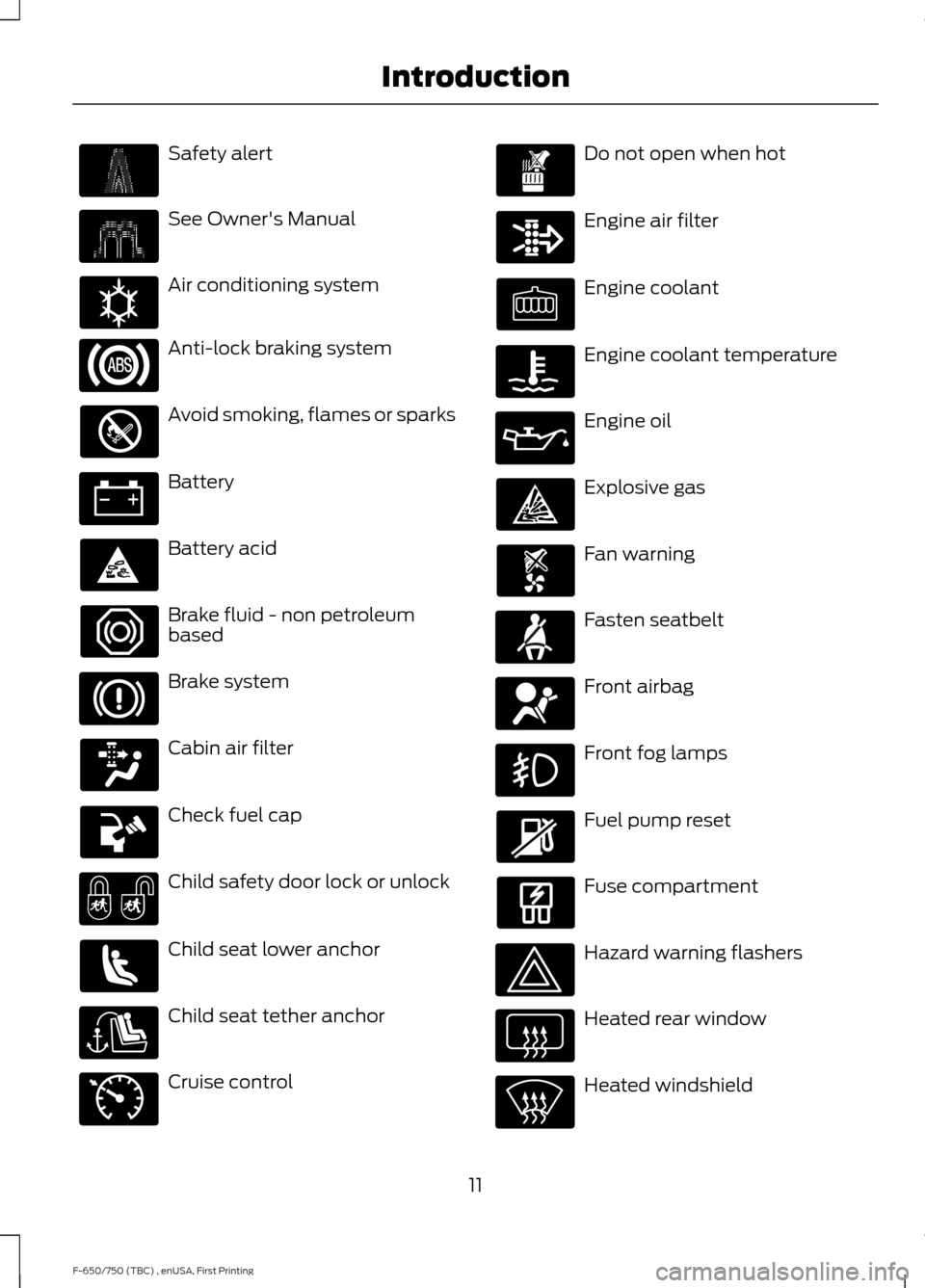
Safety alert
See Owner's Manual
Air conditioning system
Anti-lock braking system
Avoid smoking, flames or sparks
Battery
Battery acid
Brake fluid - non petroleum
based
Brake system
Cabin air filter
Check fuel cap
Child safety door lock or unlock
Child seat lower anchor
Child seat tether anchor
Cruise control Do not open when hot
Engine air filter
Engine coolant
Engine coolant temperature
Engine oil
Explosive gas
Fan warning
Fasten seatbelt
Front airbag
Front fog lamps
Fuel pump reset
Fuse compartment
Hazard warning flashers
Heated rear window
Heated windshield
11
F-650/750 (TBC) , enUSA, First Printing Introduction E162384 E71340
Page 17 of 382
vehicle development we validate that
these parts deliver the intended level of
protection as a whole system. A great way
to know for sure you are getting this level
of protection is to use genuine Ford
replacement collision parts.
Warranty on Replacement Parts
Genuine Ford and Motorcraft replacement
parts are the only replacement parts that
benefit from a Ford Warranty. The Ford
Warranty may not cover damage caused
to your vehicle as a result of failed
non-Ford parts. For additional information,
refer to the terms and conditions of the
Ford Warranty.
SPECIAL NOTICES
New Vehicle Limited Warranty
For a detailed description of what is
covered and what is not covered by your
vehicle
’s New Vehicle Limited Warranty,
refer to the Warranty Guide that is
provided to you along with your Owner ’s
Manual.
Special Instructions
For your added safety, your vehicle is fitted
with sophisticated electronic controls. MOBILE COMMUNICATIONS
EQUIPMENT WARNING
Driving while distracted can result in
loss of vehicle control, crash and
injury. We strongly recommend that
you use extreme caution when using any
device that may take your focus off the
road. Your primary responsibility is the safe
operation of your vehicle. We recommend
against the use of any hand-held device
while driving and encourage the use of
voice-operated systems when possible.
Make sure you are aware of all applicable
local laws that may affect the use of
electronic devices while driving. Using mobile communications equipment
is becoming increasingly important in the
conduct of business and personal affairs.
However, you must not compromise your
own or others’
safety when using such
equipment. Mobile communications can
enhance personal safety and security when
appropriately used, particularly in
emergency situations. Safety must be
paramount when using mobile
communications equipment to avoid
negating these benefits. Mobile
communication equipment includes, but
is not limited to, cellular phones, pagers,
portable email devices, text messaging
devices and portable two-way radios.
EXPORT UNIQUE OPTIONS
For your particular global region, your
vehicle may be equipped with features and
options that are different from the features
and options that are described in this
Owner ’s Manual. A market unique
supplement may be supplied that
complements this book. By referring to the
market unique supplement, if provided,
you can properly identify those features,
14
F-650/750 (TBC) , enUSA, First Printing Introduction
Page 30 of 382
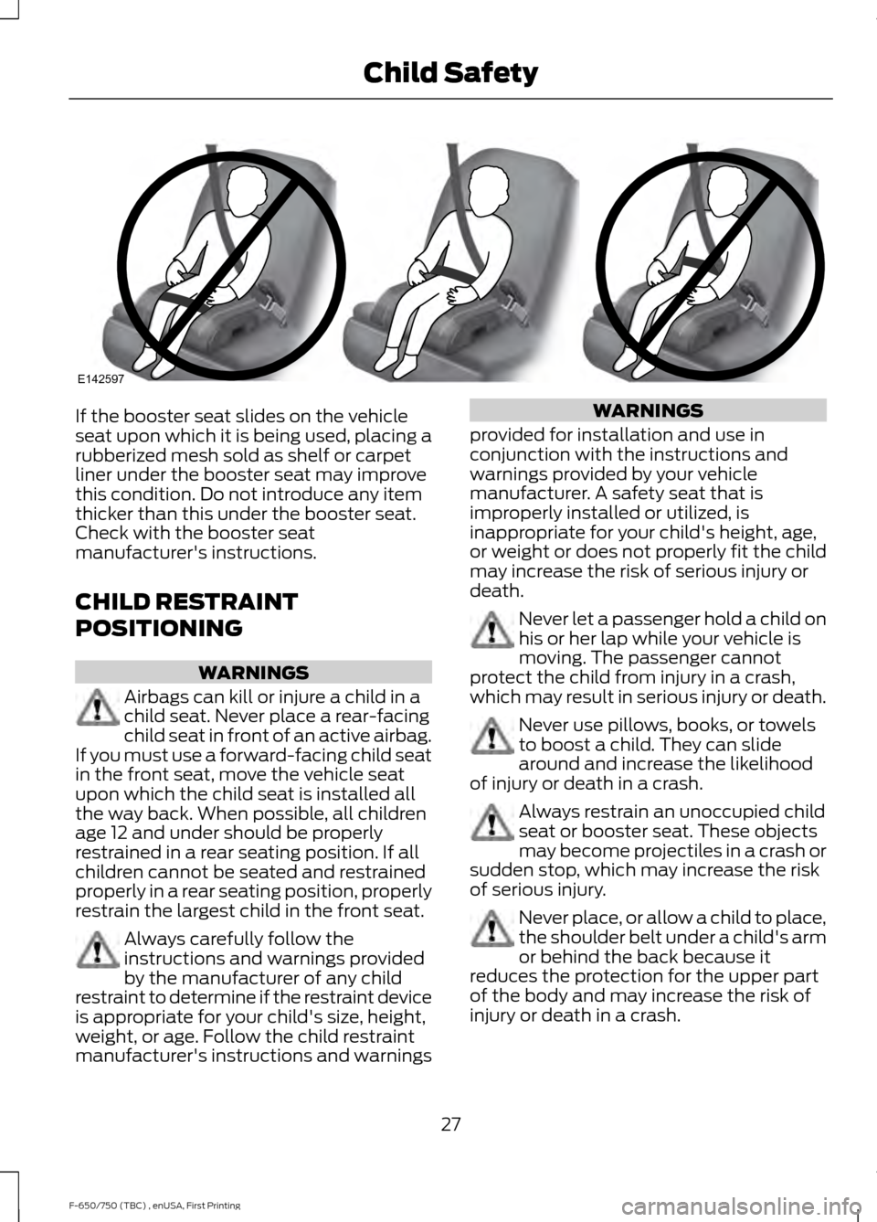
If the booster seat slides on the vehicle
seat upon which it is being used, placing a
rubberized mesh sold as shelf or carpet
liner under the booster seat may improve
this condition. Do not introduce any item
thicker than this under the booster seat.
Check with the booster seat
manufacturer's instructions.
CHILD RESTRAINT
POSITIONING
WARNINGS
Airbags can kill or injure a child in a
child seat. Never place a rear-facing
child seat in front of an active airbag.
If you must use a forward-facing child seat
in the front seat, move the vehicle seat
upon which the child seat is installed all
the way back. When possible, all children
age 12 and under should be properly
restrained in a rear seating position. If all
children cannot be seated and restrained
properly in a rear seating position, properly
restrain the largest child in the front seat. Always carefully follow the
instructions and warnings provided
by the manufacturer of any child
restraint to determine if the restraint device
is appropriate for your child's size, height,
weight, or age. Follow the child restraint
manufacturer's instructions and warnings WARNINGS
provided for installation and use in
conjunction with the instructions and
warnings provided by your vehicle
manufacturer. A safety seat that is
improperly installed or utilized, is
inappropriate for your child's height, age,
or weight or does not properly fit the child
may increase the risk of serious injury or
death. Never let a passenger hold a child on
his or her lap while your vehicle is
moving. The passenger cannot
protect the child from injury in a crash,
which may result in serious injury or death. Never use pillows, books, or towels
to boost a child. They can slide
around and increase the likelihood
of injury or death in a crash. Always restrain an unoccupied child
seat or booster seat. These objects
may become projectiles in a crash or
sudden stop, which may increase the risk
of serious injury. Never place, or allow a child to place,
the shoulder belt under a child's arm
or behind the back because it
reduces the protection for the upper part
of the body and may increase the risk of
injury or death in a crash.
27
F-650/750 (TBC) , enUSA, First Printing Child SafetyE142597
Page 50 of 382
GENERAL INFORMATION
Condensation in Lamp Assemblies
Exterior lamps have vents to
accommodate normal changes in air
pressure.
Condensation can be a natural by-product
of this design. When moist air enters the
lamp assembly through the vents, there is
a possibility that condensation can occur
when the temperature is cold. When
normal condensation occurs, a fine mist
can form on the interior of the lens. The
fine mist eventually clears and exits
through the vents during normal operation.
Clearing time may take as long as 48 hours
under dry weather conditions.
Examples of acceptable condensation are:
•
The presence of a fine mist (no streaks,
drip marks or large droplets).
• A fine mist covers less than 50% of the
lens.
Examples of unacceptable condensation
are:
• A water puddle inside the lamp.
• Streaks, drip marks or large droplets
present on the interior of the lens.
If you see any unacceptable condensation,
have your vehicle checked by an authorized
dealer. LIGHTING CONTROL •
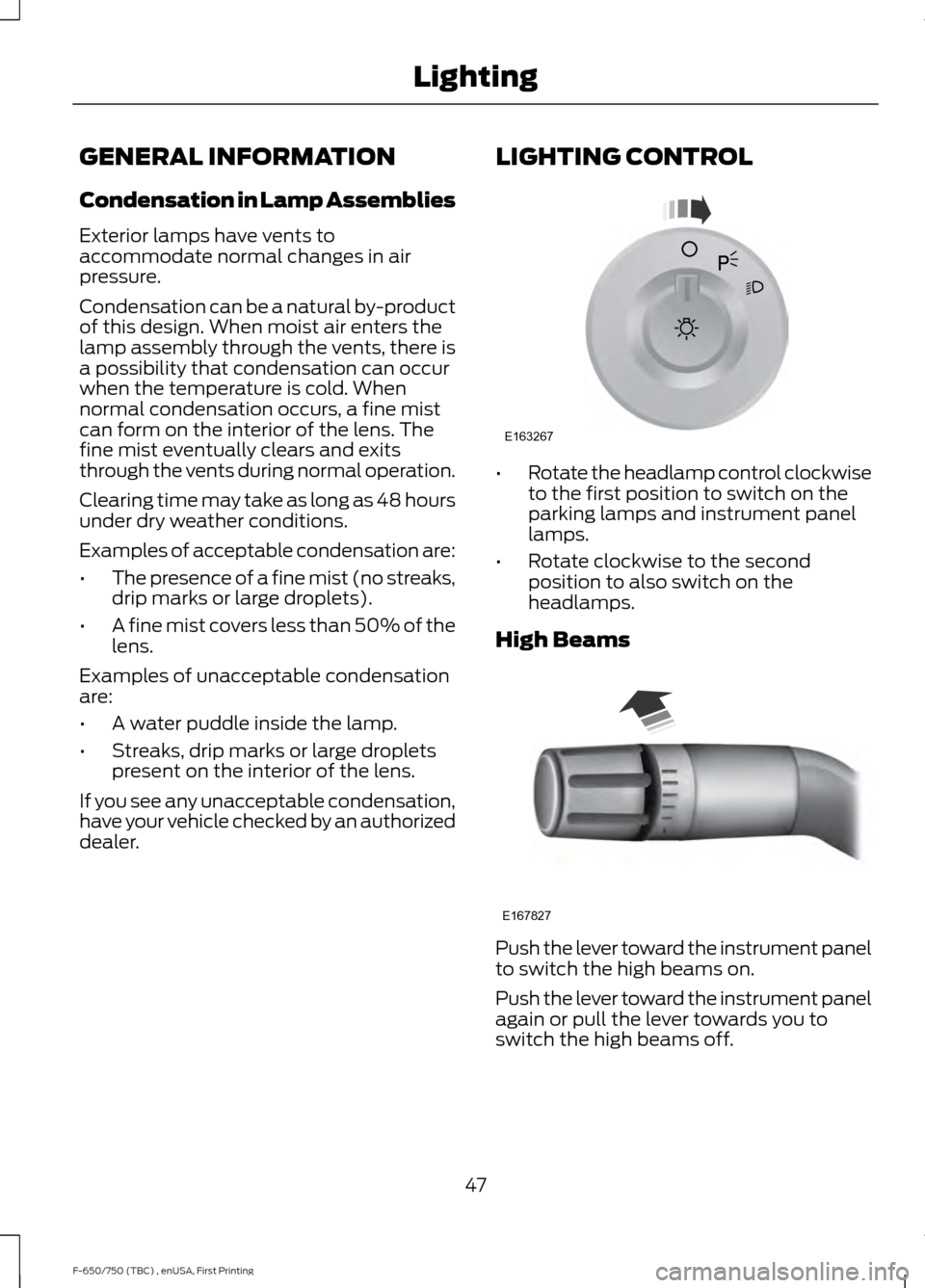
Rotate the headlamp control clockwise
to the first position to switch on the
parking lamps and instrument panel
lamps.
• Rotate clockwise to the second
position to also switch on the
headlamps.
High Beams Push the lever toward the instrument panel
to switch the high beams on.
Push the lever toward the instrument panel
again or pull the lever towards you to
switch the high beams off.
47
F-650/750 (TBC) , enUSA, First Printing LightingE163267 E167827
Page 58 of 382
Engine Oil Pressure Gauge
Indicates engine oil pressure. The needle
should stay in the normal operating range
(between L and H). If the needle falls
below the normal range, stop the vehicle,
switch off the engine and check the engine
oil level. Add oil if needed. If the oil level is
correct, have your vehicle checked by an
authorized dealer.
Engine Coolant Temperature
Gauge
WARNING
Never remove the coolant reservoir
cap while the engine is running or hot.
Indicates engine coolant temperature. At
normal operating temperature, the level
indicator is in the normal range. If the
engine coolant temperature exceeds the
normal range, stop the vehicle as soon as
safely possible, switch off the engine and
let the engine cool.
Transmission Fluid Temperature
Gauge
Indicates transmission fluid temperature.
At normal operating temperature, the level
indicator is in the normal range. If the
transmission fluid temperature exceeds
the normal range, stop the vehicle as soon
as safely possible and verify the airflow is
not restricted such as snow or debris
blocking airflow through the grille.
Special operating conditions, such as
snowplowing, towing or off-road use, can
cause higher than normal operating
temperatures. See Special Operating
Conditions Scheduled Maintenance
(page
328). Operating the transmission for extended
periods with the gauge in the higher than
normal area may cause internal
transmission damage. We recommend
altering the severity of the driving
conditions to lower the transmission
temperature into the normal range. If the
gauge continues to show high
temperatures, contact an authorized
dealer.
Fuel Gauge
Note:
The fuel gauge may vary slightly
when your vehicle is moving or on a gradient.
Switch the ignition on. The fuel gauge
indicates approximately how much fuel is
in the fuel tank. The arrow adjacent to the
fuel pump symbol indicates on which side
of your vehicle the fuel filler door is located.
The needle should move toward F when
you refuel your vehicle. If the needle points
to E after adding fuel, this indicates your
vehicle needs service soon.
After refueling, some variability in needle
position is normal:
• It may take a short time for the needle
to reach F after leaving the gas station.
This is normal and depends upon the
slope of pavement at the gas station.
• The fuel amount dispensed into the
tank is a little less or more than the
gauge indicated. This is normal and
depends upon the slope of pavement
at the gas station.
• If the gas station nozzle shuts off
before the tank is full, try a different
gas pump nozzle.
Gauge Package
(If Equipped)
If your vehicle is equipped with the optional
gauge package, it has some or all of the
following gauges:
55
F-650/750 (TBC) , enUSA, First Printing Instrument Cluster
Page 61 of 382
Trip Computer
See General Information (page 62).
Vehicle Settings and Personalization
See
General Information (page 62).
WARNING LAMPS AND
INDICATORS
The following warning lamps and
indicators alert you to a vehicle condition
that may become serious. Some lamps
illuminate when you start your vehicle to
make sure they work. If any lamps remain
on after starting your vehicle, refer to the
respective system warning lamp for further
information.
Note: Some warning indicators appear in
the information display and function the
same as a warning lamp but do not display
when you start your vehicle.
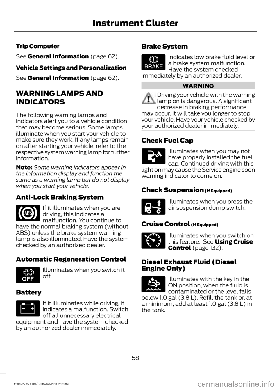
Anti-Lock Braking System If it illuminates when you are
driving, this indicates a
malfunction. You continue to
have the normal braking system (without
ABS) unless the brake system warning
lamp is also illuminated. Have the system
checked by an authorized dealer.
Automatic Regeneration Control Illuminates when you switch it
off.
Battery If it illuminates while driving, it
indicates a malfunction. Switch
off all unnecessary electrical
equipment and have the system checked
by an authorized dealer immediately. Brake System Indicates low brake fluid level or
a brake system malfunction.
Have the system checked
immediately by an authorized dealer. WARNING
Driving your vehicle with the warning
lamp on is dangerous. A significant
decrease in braking performance
may occur. It will take you longer to stop
your vehicle. Have your vehicle checked by
your authorized dealer immediately. Check Fuel Cap
Illuminates when you may not
have properly installed the fuel
cap. Continued driving with this
light on may cause the Service engine soon
warning indicator to come on.
Check Suspension
(If Equipped) Illuminates when you press the
air suspension dump switch.
Cruise Control
(If Equipped) Illuminates when you switch on
this feature. See
Using Cruise
Control (page 132).
Diesel Exhaust Fluid (Diesel
Engine Only) Illuminates with the key in the
ON position, when the fluid is
contaminated or the level falls
below
1.0 gal (3.8 L). Refill the tank or, at
a minimum, add at least 1.0 gal (3.8 L) in
the tank.
58
F-650/750 (TBC) , enUSA, First Printing Instrument Cluster E208811 E209041 E208808 E71340 E163176
Page 73 of 382
MANUAL CLIMATE CONTROL
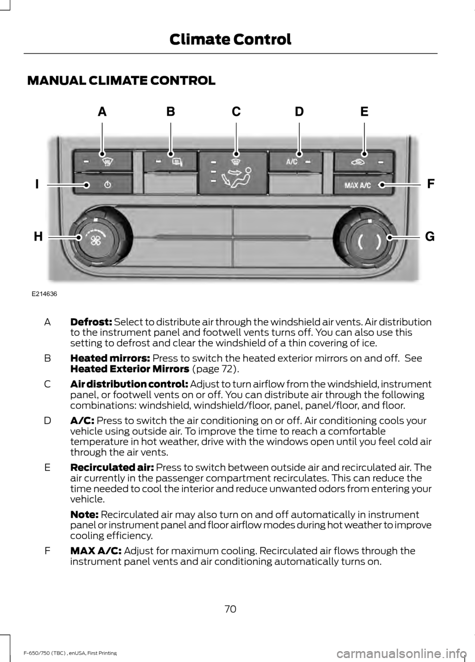
Defrost: Select to distribute air through the windshield air vents. Air distribution
to the instrument panel and footwell vents turns off. You can also use this
setting to defrost and clear the windshield of a thin covering of ice.
A
Heated mirrors: Press to switch the heated exterior mirrors on and off. See
Heated Exterior Mirrors (page 72).
B
Air distribution control: Adjust to turn airflow from the windshield, instrument
panel, or footwell vents on or off. You can distribute air through the following
combinations: windshield, windshield/floor, panel, panel/floor, and floor.
C
A/C:
Press to switch the air conditioning on or off. Air conditioning cools your
vehicle using outside air. To improve the time to reach a comfortable
temperature in hot weather, drive with the windows open until you feel cold air
through the air vents.
D
Recirculated air:
Press to switch between outside air and recirculated air. The
air currently in the passenger compartment recirculates. This can reduce the
time needed to cool the interior and reduce unwanted odors from entering your
vehicle.
E
Note:
Recirculated air may also turn on and off automatically in instrument
panel or instrument panel and floor airflow modes during hot weather to improve
cooling efficiency.
MAX A/C:
Adjust for maximum cooling. Recirculated air flows through the
instrument panel vents and air conditioning automatically turns on.
F
70
F-650/750 (TBC) , enUSA, First Printing Climate ControlE214636
Page 87 of 382
GENERAL INFORMATION
WARNINGS
Extended idling at high engine
speeds can produce very high
temperatures in the engine and
exhaust system, creating the risk of fire or
other damage. Do not park, idle or drive your vehicle
on dry grass or other dry ground
cover. The emission system heats up
the engine compartment and exhaust
system, creating the risk of fire. Do not start the engine in a closed
garage or in other enclosed areas.
Exhaust fumes can be toxic. Always
open the garage door before you start the
engine. If you smell exhaust fumes inside
your vehicle, have your vehicle
checked by your authorized dealer
immediately. Do not drive your vehicle if
you smell exhaust fumes. If you disconnect the battery, your vehicle
may exhibit some unusual driving
characteristics for approximately 5 miles
(8 kilometers) after you reconnect it. This
is because the engine management system
must realign itself with the engine. You can
disregard any unusual driving
characteristics during this period.
The powertrain control system meets all
Canadian interference-causing equipment
standard requirements regulating the
impulse electrical field or radio noise.
When you start the engine, avoid pressing
the accelerator pedal before and during
operation. Only use the accelerator pedal
when you have difficulty starting the
engine. If your vehicle is operated in a heavy snow
storm or blowing snow conditions, the
engine air induction may become partially
clogged with snow and ice. If this occurs,
the engine may experience a significant
reduction in power output. At the earliest
opportunity, clear all the snow and ice
away from the air induction inlet.
IGNITION SWITCH
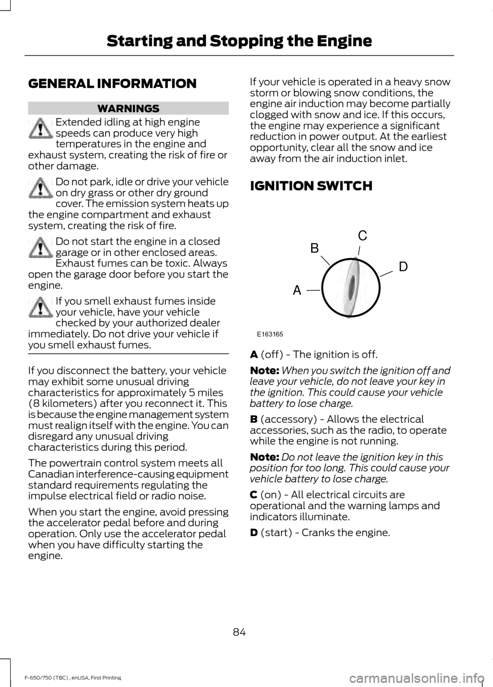
A (off) - The ignition is off.
Note: When you switch the ignition off and
leave your vehicle, do not leave your key in
the ignition. This could cause your vehicle
battery to lose charge.
B
(accessory) - Allows the electrical
accessories, such as the radio, to operate
while the engine is not running.
Note: Do not leave the ignition key in this
position for too long. This could cause your
vehicle battery to lose charge.
C
(on) - All electrical circuits are
operational and the warning lamps and
indicators illuminate.
D
(start) - Cranks the engine.
84
F-650/750 (TBC) , enUSA, First Printing Starting and Stopping the EngineC
D
B
A
E163165
Page 89 of 382
•
Open the windows at least 1 in (3 cm).
• Set your climate control to outside air.
STARTING A DIESEL ENGINE WARNING
Operation of a diesel engine near
flammable vapors in the air may
cause the engine speed to increase
uncontrollably and over speed. If this
situation occurs, mechanical damage, fire,
explosion, personal injury or death could
result. Turning off the ignition key does not
slow or stop the engine due to
uncontrollable fueling of the engine
through flammable vapors being drawn
into the engine air inlet. Operation of
components, for example starter,
alternator, electric motors and static
electricity could also ignite flammable
vapors. Do not operate your vehicle in the
possible presence of flammable vapors
unless both a complete hazard analysis is
carried out and necessary additional safety
processes and/or equipment, for example
vapor testing, air intake shutoff devices
and ventilation are utilized. You are
responsible for using those processes
and/or equipment to make sure that the
diesel engine and all other components on
your vehicle can be operated safely under
the specific conditions and hazards that
may be encountered. Read all starting instructions carefully
before you start your vehicle.
Diesel Engine Fast Start Glow Plug
System
The diesel engine glow system consists of:
•
Eight glow plugs (one per cylinder)
• Glow Plug Control Module
• Engine Coolant Temperature sensor •
Barometric pressure sensor
• Environmental temperature sensor
The powertrain and glow plug control
modules electronically control the glow
plug system. After you switch the ignition
on the glow plug control module
immediately energizes the glow plugs. The
glow plug control module using the engine
coolant temperature, barometric pressure
sensor and environmental temperature
sensor will determine how long the glow
plugs stay energized. The required time for
the glow plugs to be energized decreases
as the coolant temperature, barometric
pressure and environmental temperature
increase.
Before starting the engine, check the
following:
• Make sure all occupants have fastened
their safety belts.
• Make sure the headlamps and
electrical accessories are off.
• Make sure the parking brake is on.
• Make sure the transmission is in park
(P) or neutral (N).
• Turn the ignition key to the on position.
Note: Do not press the accelerator during
starting.
Cold Weather Starting WARNINGS
Do not use starting fluid, for example
ether, in the air intake system (see
air filter decal). Such fluid could
cause immediate explosive damage to the
engine and possible personal injury. Do not add gasoline, gasohol, alcohol
or Kerosene to diesel fuel. This
practice creates a serious fire hazard
and causes engine performance problems. 86
F-650/750 (TBC) , enUSA, First Printing Starting and Stopping the Engine