jump start terminals FORD F650 2017 13.G Owners Manual
[x] Cancel search | Manufacturer: FORD, Model Year: 2017, Model line: F650, Model: FORD F650 2017 13.GPages: 382, PDF Size: 5.18 MB
Page 154 of 382

Note:
Use only a 12-volt supply to start your
vehicle.
Note: Do not disconnect the battery of the
disabled vehicle as this could damage the
vehicle electrical system.
Park the booster vehicle close to the hood
of the disabled vehicle, making sure the
two vehicles do not touch.
Connecting the Jumper Cables WARNINGS
Do not attach the cables to fuel lines,
engine rocker covers, the intake
manifold or electrical components
as grounding points. Stay clear of moving
parts. To avoid reverse polarity
connections, make sure that you correctly
identify the positive (+) and negative (-)
terminals on both the disabled and booster
vehicles before connecting the cables. Do not attach the end of the positive
cable to the studs or L-shaped eyelet
located above the positive (+)
terminal of your vehicle ’s battery. High
current may flow through and cause
damage to the fuses. Do not connect the end of the
second cable to the negative (-)
terminal of the battery to be jumped.
A spark may cause an explosion of the
gases that surround the battery. Note:
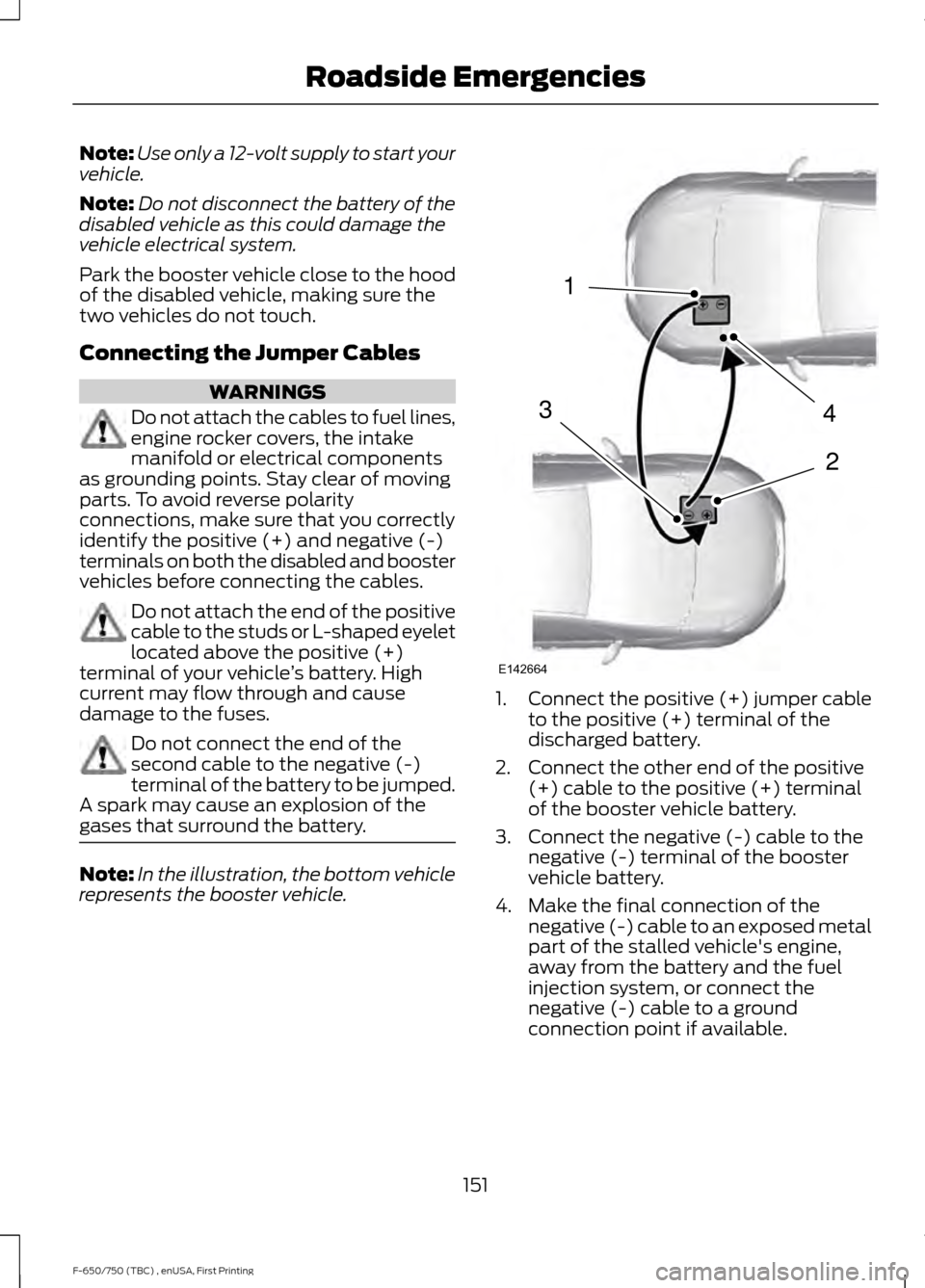
In the illustration, the bottom vehicle
represents the booster vehicle. 1.
Connect the positive (+) jumper cable
to the positive (+) terminal of the
discharged battery.
2. Connect the other end of the positive (+) cable to the positive (+) terminal
of the booster vehicle battery.
3. Connect the negative (-) cable to the negative (-) terminal of the booster
vehicle battery.
4. Make the final connection of the negative (-) cable to an exposed metal
part of the stalled vehicle's engine,
away from the battery and the fuel
injection system, or connect the
negative (-) cable to a ground
connection point if available.
151
F-650/750 (TBC) , enUSA, First Printing Roadside Emergencies4
2
1
3
E142664
Page 220 of 382

2.
Rotate the filter fully counterclockwise
until the peg is at the far end of the slot.
3. Pull the filter straight up from the bracket and discard the filter.
Installation
1. Install the new filter into the filter bracket. Turn the filter clockwise to
lock it in place.
2. Reconnect the fuel lines.
3. Switch the ignition on for 30 seconds and then switch the ignition off. Repeat
this operation six times in a row to
purge any trapped air from the fuel
system.
ELECTRICAL SYSTEM
INSPECTION
Periodically inspect electrical connectors
on the outside of the cab and on the engine
and frame for corrosion and tightness.
Exposed terminals, such as the fuel sender,
cranking motor, alternator and
feed-through studs, should be cleaned and re-coated with a lubricant sealing grease
such as Motorcraft Silicone Brake Caliper
Grease and Dielectric Compound XG-3, or
equivalent. This should include the ground
cable connector for batteries, engine and
cab as well as the jump-starting stud.
Accessory Feed Connections
Vehicle electrical systems are complex and
often include powertrain components,
such as engine and transmission controls,
instrument panels and ABS. While most
systems operate on battery voltage (12
volts), some systems can be as high as 90
volts or as low as five volts. See the
Electrical Circuit Diagram Manuals,
available from your vehicle
’s manufacturer,
to make sure that any extra body lights and
accessory connections to circuits are both
appropriate and not overloaded. Do not
make modifications to any vehicle control
system without first contacting an
authorized dealer.
AIR INDUCTION SYSTEM
INSPECTION WARNING
When performing maintenance to
any turbocharged engine with engine
air inlet piping disconnected, keep
loose clothing, jewelry and long hair away
from the engine air inlet piping. A
turbocharger compressor air inlet
protective shield should be installed over
the turbocharger air inlet to reduce the risk
of personal injury or death. Perform a complete inspection of the air
induction system annually.
217
F-650/750 (TBC) , enUSA, First Printing MaintenanceE226214
2
3