service FORD F650/750 2019 Owner's Manual
[x] Cancel search | Manufacturer: FORD, Model Year: 2019, Model line: F650/750, Model: FORD F650/750 2019Pages: 387, PDF Size: 4.78 MB
Page 107 of 387
Illumination of the service engine soon
indicator, charging system warning light or
the temperature warning light, fluid leaks,
strange odors, smoke or loss of engine
power could indicate that the emission
control system is not working properly.
An improperly operating or damaged
exhaust system may allow exhaust to
enter the vehicle. Have a damaged or
improperly operating exhaust system
inspected and repaired immediately.
Do not make any unauthorized changes to
your vehicle or engine. By law, vehicle
owners and anyone who manufactures,
repairs, services, sells, leases, trades
vehicles, or supervises a fleet of vehicles
are not permitted to intentionally remove
an emission control device or prevent it
from working. Information about your
vehicle
’s emission system is on the Vehicle
Emission Control Information Decal
located on or near the engine. This decal
also lists engine displacement.
Please consult your warranty information
for complete details.
On-Board Diagnostics (OBD-II)
Your vehicle has a computer known as the
on-board diagnostics system (OBD-II) that
monitors the engine ’s emission control
system. The system protects the
environment by making sure that your
vehicle continues to meet government
emission standards. The OBD-II system
also assists a service technician in properly
servicing your vehicle. When the service engine soon
indicator illuminates, the OBD-II
system has detected a
malfunction. Temporary malfunctions may
cause the service engine soon indicator to
illuminate. Examples are: 1. Your vehicle has run out of fuel
—the
engine may misfire or run poorly.
2. Poor fuel quality or water in the fuel —the engine may misfire or run
poorly.
3. The fuel fill inlet may not have closed properly. See Refueling (page 97).
4. Driving through deep water —the
electrical system may be wet.
You can correct these temporary
malfunctions by filling the fuel tank with
good quality fuel, properly closing the fuel
fill inlet or letting the electrical system dry
out. After three driving cycles without these
or any other temporary malfunctions
present, the service engine soon indicator
should stay off the next time you start the
engine. A driving cycle consists of a cold
engine startup followed by mixed city and
highway driving. No additional vehicle
service is required.
If the service engine soon indicator remains
on, have your vehicle serviced at the first
available opportunity. Although some
malfunctions detected by the OBD-II may
not have symptoms that are apparent,
continued driving with the service engine
soon indicator on can result in increased
emissions, lower fuel economy, reduced
engine and transmission smoothness and
lead to more costly repairs.
Readiness for Inspection and
Maintenance (I/M) Testing
Some state and provincial and local
governments may have
Inspection/Maintenance (I/M) programs
to inspect the emission control equipment
on your vehicle. Failure to pass this
inspection could prevent you from getting
a vehicle registration. If the service engine soon
indicator is on or the bulb does
not work, your vehicle may need
service. See On-Board Diagnostics.
104
F650750 (TBC) , enUSA, Edition date: 201804, Second-Printing Engine Emission Control
Page 108 of 387
Your vehicle may not pass the I/M test if
the service engine soon indicator is on or
not working properly (bulb is burned out),
or if the OBD-II system has determined
that some of the emission control systems
have not been properly checked. In this
case, the vehicle is not ready for I/M
testing.
If the vehicle
’s engine or transmission has
just been serviced, or the battery has
recently run down or been replaced, the
OBD-II system may indicate that the
vehicle is not ready for I/M testing. To
determine if the vehicle is ready for I/M
testing, turn the ignition key to the on
position for 15 seconds without cranking
the engine. If the service engine soon
indicator blinks eight times, it means that
the vehicle is not ready for I/M testing; if
the service engine soon indicator stays on
solid, it means that your vehicle is ready
for I/M testing.
The OBD-II system checks the emission
control system during normal driving. A
complete check may take several days.
If the vehicle is not ready for I/M testing,
you can perform the following driving cycle
consisting of mixed city and highway
driving:
1. 15 minutes of steady driving on an expressway or highway followed by 20
minutes of stop-and-go driving with at
least four 30-second idle periods.
2. Allow your vehicle to sit for at least eight hours with the ignition off. Then,
start the vehicle and complete the
above driving cycle. The vehicle must
warm up to its normal operating
temperature. Once started, do not turn
off the vehicle until the above driving
cycle is complete.
If the vehicle is still not ready for I/M
testing, you need to repeat the above
driving cycle. SELECTIVE CATALYTIC
REDUCTANT SYSTEM - DIESEL
Your vehicle may have a selective catalytic
reduction system. The system helps reduce
emission levels of oxides of nitrogen from
the exhaust system. The system
automatically injects diesel exhaust fluid
into the exhaust system to enable correct
selective catalytic reduction system
function.
Note:
Selective catalytic reduction systems
are not fitted to vehicles in markets where
only high-sulfur diesel fuel is available.
Diesel Exhaust Fluid Level
In order for the system to operate correctly
you must maintain the diesel exhaust fluid
level.
A warning message appears in the
information display when the diesel
exhaust fluid level is low. If a warning
message appears, refill the diesel exhaust
fluid tank as soon as possible. See
Information Messages (page 67).
Filling the Diesel Exhaust Fluid
Tank WARNING:
Keep diesel exhaust
fluid out of reach of children. Avoid
contact with skin, eyes or clothing. In
case of contact with your eyes, flush
immediately with water and get prompt
medical attention. In case of contact
with your skin, clean immediately with
soap and water. If you swallow any
diesel exhaust fluid, drink plenty of
water, call a physician immediately.
105
F650750 (TBC) , enUSA, Edition date: 201804, Second-Printing Engine Emission Control
Page 112 of 387
•
The system has a diesel exhaust fluid
quality sensor. Dilution of diesel
exhaust fluid or use of any other liquid
in the SCR system leads to a diesel
exhaust fluid system fault, eventually
leading to the vehicle only operating in
idle-only mode.
• Do not dilute diesel exhaust fluid with
water or any other liquid.
• An ammonia odor may be smelled
when the cap is removed or during
refill. Refill diesel exhaust fluid in a well
ventilated area.
Typical Diesel Exhaust Fluid Usage
When Using the Power Take Off (PTO) Continuous PTO use—Minimal PTO use
0–7,800 mi (0– 12,550 km)
Contaminated Diesel Exhaust
Fluid or Inoperative Selective
Catalytic Reduction System
Selective catalytic reduction systems are
sensitive to contamination of the diesel
exhaust fluid. Maintaining the purity of the
fluid is important to avoid system
malfunctions. If you remove or drain the
diesel exhaust fluid tank, do not use the
same fluid to refill the tank. The system
has a sensor to monitor fluid quality. A warning lamp illuminates and
a message appears in the
information display if the system
becomes contaminated or inoperative. Continued driving without replacing diesel
exhaust fluid or having the selective
catalytic reduction system repaired results
in the following actions as required by the
California Air Resources Board (CARB) and
U.S. Environmental Protection Agency
(EPA):
•
Within a preset distance to empty,
speed is limited upon vehicle restart.
Prior to this occurring a message
appears in the information display.
• Further vehicle operation without
replacing contaminated diesel exhaust
fluid causes the engine to enter an
idle-only condition. This only occurs
upon vehicle refueling, vehicle idling in
park for 1 hour, or engine shutdown for
10 minutes or more and is indicated by
a message in the information display
indicating required actions to resume
normal operation.
Note: For vehicle speed limiting or idle-only
condition, normal vehicle operation resumes
when you repair the contaminated system.
To service a contaminated or inoperative
system, see an authorized dealer.
DIESEL PARTICULATE FILTER
Your vehicle has a diesel particulate filter.
The diesel particulate filter is an inline filter
in the exhaust system that reduces carbon
emissions by trapping exhaust particles
before they reach the tailpipe. The diesel
particulate filter looks similar to a
traditional exhaust catalyst, except larger,
and is part of the exhaust system under
your vehicle. The filter couples to a diesel
oxidation catalyst that reduces the amount
of harmful exhaust emitted from the
tailpipe. As soot gathers in the system, it
begins to restrict the filter. Periodically, you
need to clean the soot that gathers inside
the filter. You can clean the soot in two
different ways, passive regeneration and
active regeneration. Both methods occur
109
F650750 (TBC) , enUSA, Edition date: 201804, Second-Printing Engine Emission ControlE163176
Page 115 of 387
Before you start operator commanded
regeneration, do the following:
•
Shift into park (P) or if you have an
RNDM selector shift into neutral (N)
and apply the parking and or air brake,
on stable, level ground.
• Park your vehicle outside of any
structure.
• Park your vehicle 10– 15 ft (3–5 m)
away from any obstructions and away
from materials that can easily combust
or melt, for example paper, leaves,
petroleum products, fuels, plastics and
other dry organic material.
• Make sure there is a minimum of 1/8
tank of fuel.
• Make sure all fluids are at proper levels.
How to Start Operator Commanded
Regeneration WARNING:
Stay clear of the
exhaust tailpipe during regeneration. Hot
exhaust gases can burn you badly.
Note: You cannot use the operator
commanded regeneration until the diesel
particulate filter load percentage has
reached 100%. The diesel particulate filter
load percentage fluctuates up and down
when driving your vehicle due to active and
passive regenerations.
Note: During the use of operator
commanded regeneration, you may observe
a light amount of white smoke. This is
normal. You may not be able to use
operator commanded
regeneration if the service engine
soon warning lamp appears in the
information display Information Display Procedure
Start your vehicle engine and when it has
reached the normal operating temperature,
press the information display control
button on the steering wheel until Exhaust
Filter XX%/FULL is displays. Operator
commanded regeneration can only be
initiated when FULL
See Information
Display Control (page 47). If a message
advising that the exhaust filter is full
appears in the information display, press
the down arrow button to set the display
to
Y. Answer yes to this prompt and then
follow the next prompts regarding exhaust
position required to initiate operator
commanded regeneration. Be sure to
understand each prompt. If you are not
sure what is being asked by each prompt,
contact an authorized dealer. The display
confirms the operation has started and
when it has finished.
If the diesel particulate filter is near or at
saturation, a message requesting
permission to initiate filter cleaning
appears in the information display only if
viewing the Exhaust Filter Status message.
See
Information Messages (page 67).
Answer yes to this prompt and then follow
the next prompts regarding exhaust
position required to initiate operator
commanded regeneration. Be sure to
understand each prompt. If you are not
sure what is being asked by each prompt,
contact an authorized dealer. The display
confirms the operation has started and
when it has finished. You can also drive to
clean the filter. When the system is at the point
of oversaturation, the service
engine warning lamp illuminates
and a message appears in the information
display. You cannot initiate filter cleaning.
You must have your vehicle checked as
soon as possible.
112
F650750 (TBC) , enUSA, Edition date: 201804, Second-Printing Engine Emission Control
Page 116 of 387
Once operator commanded regeneration
starts, engine speed increases to
approximately 2000 rpm and the cooling
fan speed increases. You will hear a
change in audible sound due to engine
speed and cooling fan speed increases.
It is not necessary to open the hood on the
engine compartment. Once operator
commanded regeneration completes, the
engine speed returns to normal idling. The
exhaust system remains very hot for
several minutes even after regeneration is
complete. Do not reposition the vehicle
over materials that could burn until the
exhaust system has had sufficient time to
cool. Depending on the amount of soot
collected by the diesel particulate filter,
ambient temperature and altitude,
operator commanded regeneration lasts
approximately 30 minutes.
Operator Commanded Regeneration
with Automatic Regeneration Control
(If Equipped)
If your vehicle is operated with significant
stationary operation, low speed drive
cycles less than 25 mph (40 km/h), short
drive cycles, drive time less than 15 minutes
or the vehicle does not fully warm up,
passive and active regeneration may not
sufficiently clean the diesel particulate
filter system. You can switch off automatic
regeneration until better driving conditions
are available, for example steady high
speed driving. You can then switch
automatic regeneration back on to clean
the diesel particulate filter.
Switching Automatic Regeneration
Control On and Off
To switch operator commanded
regeneration on and off, use the
information display control on the steering
wheel. See Information Display Control
(page
47). Scroll to the exhaust cleaning
message and then select Y or N to switch
it On or Off. How to Interrupt or Cancel Operator
Commanded Regeneration
If you need to cancel the operator
commanded regeneration, pressing the
brake, accelerator or switching the engine
off stops the procedure. Depending on the
amount of time you allowed the operator
commanded regeneration to operate, soot
may not have had sufficient time to be fully
eliminated, but the exhaust system and
exhaust gas may still be hot. If you shut
your vehicle off during operator
commanded regeneration, you may notice
turbo flutter. This is a normal consequence
caused by shutting off a diesel engine
during boosted operation and is considered
normal.
Filter Service and Maintenance
Over time, a slight amount of ash builds
up in the diesel particulate filter, which is
not removed during the regeneration
process. The filter may need to be replaced
with a new or remanufactured part at
approximately 250,000 mi (400,000 km).
Actual mileage varies depending on engine
and vehicle operating conditions.
If filter service is required, the
engine control system warning
lamp illuminates in the
information display. If there are any issues with the
diesel particulate filter system,
the engine control system
warning lamp and a service
engine soon warning lamp
illuminate to inform you that
your vehicle requires service. Have your
vehicle checked as soon as possible.
113
F650750 (TBC) , enUSA, Edition date: 201804, Second-Printing Engine Emission Control
Page 122 of 387
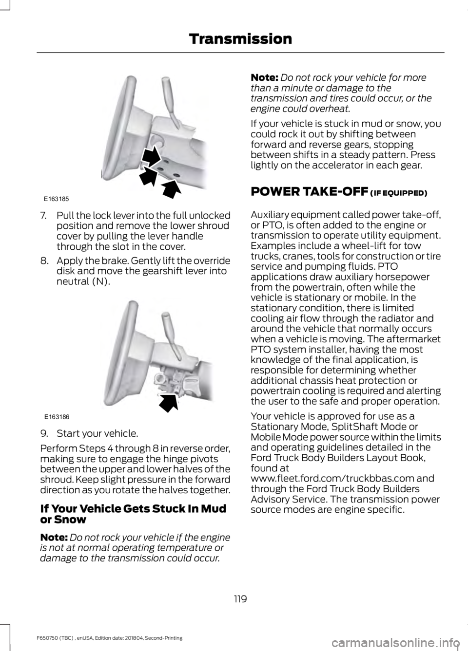
7.
Pull the lock lever into the full unlocked
position and remove the lower shroud
cover by pulling the lever handle
through the slot in the cover.
8. Apply the brake. Gently lift the override
disk and move the gearshift lever into
neutral (N). 9. Start your vehicle.
Perform Steps 4 through 8 in reverse order,
making sure to engage the hinge pivots
between the upper and lower halves of the
shroud. Keep slight pressure in the forward
direction as you rotate the halves together.
If Your Vehicle Gets Stuck In Mud
or Snow
Note:
Do not rock your vehicle if the engine
is not at normal operating temperature or
damage to the transmission could occur. Note:
Do not rock your vehicle for more
than a minute or damage to the
transmission and tires could occur, or the
engine could overheat.
If your vehicle is stuck in mud or snow, you
could rock it out by shifting between
forward and reverse gears, stopping
between shifts in a steady pattern. Press
lightly on the accelerator in each gear.
POWER TAKE-OFF (IF EQUIPPED)
Auxiliary equipment called power take-off,
or PTO, is often added to the engine or
transmission to operate utility equipment.
Examples include a wheel-lift for tow
trucks, cranes, tools for construction or tire
service and pumping fluids. PTO
applications draw auxiliary horsepower
from the powertrain, often while the
vehicle is stationary or mobile. In the
stationary condition, there is limited
cooling air flow through the radiator and
around the vehicle that normally occurs
when a vehicle is moving. The aftermarket
PTO system installer, having the most
knowledge of the final application, is
responsible for determining whether
additional chassis heat protection or
powertrain cooling is required and alerting
the user to the safe and proper operation.
Your vehicle is approved for use as a
Stationary Mode, SplitShaft Mode or
Mobile Mode power source within the limits
and operating guidelines detailed in the
Ford Truck Body Builders Layout Book,
found at
www.fleet.ford.com/truckbbas.com and
through the Ford Truck Body Builders
Advisory Service. The transmission power
source modes are engine specific.
119
F650750 (TBC) , enUSA, Edition date: 201804, Second-Printing TransmissionE163185 E163186
Page 125 of 387
GENERAL INFORMATION
WARNING: Do not apply the brake
pedal and accelerator pedal
simultaneously. Applying both pedals
simultaneously for more than a few
seconds will limit engine performance,
which may result in difficulty maintaining
speed in traffic and could lead to serious
injury.
Note: Occasional brake noise is normal. If
a metal-to-metal, continuous grinding or
continuous squeal sound is present, the
brake linings may be worn-out. Have the
system checked as soon as possible. If your
vehicle has continuous vibration or shudder
in the steering wheel while braking, have it
checked by an authorized dealer.
All standard equipment brakes are
self-adjusting. Automatic adjustment,
when required, occurs whenever you apply
and release the brakes during forward or
reverse operation.
Know the required stopping distances for
all driving conditions you may encounter.
For longer brake lining life, take full
advantage of engine braking power when
coming to a stop.
Wet brakes result in reduced braking
efficiency. Gently press the brake pedal a
few times when driving from a car wash or
standing water to dry the brakes.
If the brakes do not grip well:
• Check brake adjustment.
• Check the brake linings for excessive
wear.
• Check the system air pressure on
vehicles with air brakes. •
Let the brakes cool if you have been
using them excessively, as in mountain
driving or after several fast, high-speed
stops.
• If you have been driving through deep
water, gently apply the brakes several
times while your vehicle is moving
slowly.
Brake Over Accelerator
In the event the accelerator pedal
becomes stuck or entrapped, apply steady
and firm pressure to the brake pedal to
slow the vehicle and reduce engine power.
If you experience this condition, apply the
brakes and bring your vehicle to a safe
stop. Move the transmission to park (P),
switch the engine off and apply the parking
brake. Inspect the accelerator pedal for
any interference. If none are found and the
condition persists, have your vehicle towed
to the nearest authorized dealer
Anti-lock Brake System
This system helps you maintain steering
control during emergency stops by keeping
the brakes from locking. This lamp momentarily
illuminates when you switch the
ignition on. If the light does not
illuminate during start up, remains on or
flashes, the system may be disabled. Have
the system checked by an authorized
dealer. If you connect a PLC trailer with
the ignition on, the trailer ABS
light also illuminates. If the light
fails to illuminate, if it remains on after you
start the vehicle or continues to flash, have
the system serviced immediately.
See
Warning Lamps and Indicators
(page 60).
122
F650750 (TBC) , enUSA, Edition date: 201804, Second-Printing Brakes E210335
Page 126 of 387
If the system is disabled, normal
braking is still effective. If the
brake warning lamp illuminates
when you release the parking brake, have
the system checked by an authorized
dealer. It also illuminates momentarily
when you switch the ignition on to confirm
the lamp is functional. If it does not
illuminate when you switch the ignition on,
or begins to flash at any time, have the
system checked by an authorized dealer.
HINTS ON DRIVING WITH
ANTI-LOCK BRAKES
The anti-lock braking system does not
eliminate the risks when:
• You drive too closely to the vehicle in
front of you.
• Your vehicle is hydroplaning.
• You take corners too fast.
• The road surface is poor.
Note: If the system activates, the brake
pedal may pulse and may travel further.
Maintain pressure on the brake pedal. You
may also hear a noise from the system. This
is normal.
PARKING BRAKE
Hydraulic Brakes (If Equipped) WARNING:
Always set the parking
brake and leave your vehicle with the
transmission in park (P). WARNING:
This control is for
parking only. Do not leave the vehicle
unattended after setting the parking
brake without placing the transmission
in park (P). We recommend using wheel
chocks for hilly or off-road
circumstances. WARNING:
Unexpected and
possibly sudden vehicle movement may
occur if you do not take these
precautions. WARNING:
If the parking brake is
fully released, but the brake warning
lamp remains illuminated, the brakes
may not be working properly. Have your
vehicle checked as soon as possible.
Apply the parking brake whenever the
vehicle is parked. To set the parking brake,
pull the handle up until it snaps into the
locked position.
When the parking brake is out of
adjustment, seek service immediately. The parking brake warning lamp
in the instrument cluster
illuminates, and remains
illuminated (when you switch on the
ignition), until you release the parking
brake. 123
F650750 (TBC) , enUSA, Edition date: 201804, Second-Printing BrakesE209041 E208810 E210347
Page 127 of 387
Push the palm release lever (A) on the
parking brake handle (B) and push down
as far as possible to release the brake.
Driving with the parking brake on causes
the brakes to wear out quickly and reduces
fuel economy.
We recommend you not use the parking
brake to stop a moving vehicle. However,
if the normal brakes fail, you can use the
parking brake to stop your vehicle in an
emergency. Since the parking brake only
applies retardation to the rear wheels, the
vehicle's stopping distance increases
greatly and the handling of your vehicle is
adversely affected.
Releasing Spring Manually
WARNING: Do not attempt to
disassemble the parking brake air
chamber under any circumstances as
this may cause serious injury. WARNING:
Block the wheels to
help prevent the vehicle from moving. WARNING:
Unexpected and
possibly sudden vehicle movement may
occur if you do not take these
precautions.
If you release hydraulic pressure from the
spring brake chamber, the power spring
applies the brake. If the hydraulic pressure
can be re-established, you must release
the spring brake in order to move your
vehicle. Air Brakes
(If Equipped) WARNING:
This control is for
parking only. Do not leave the vehicle
unattended after setting the parking
brake without placing the transmission
in park (P). We recommend using wheel
chocks for hilly or off-road
circumstances.
If the service brakes fail to operate while
your vehicle is moving, you can make an
emergency stop with the parking brake.
Since the parking brake only applies
stopping power to the rear wheels, your
vehicle ’s stopping distance greatly
increases and the handling of your vehicle
is adversely affected. Make repairs
immediately to an inoperative air brake
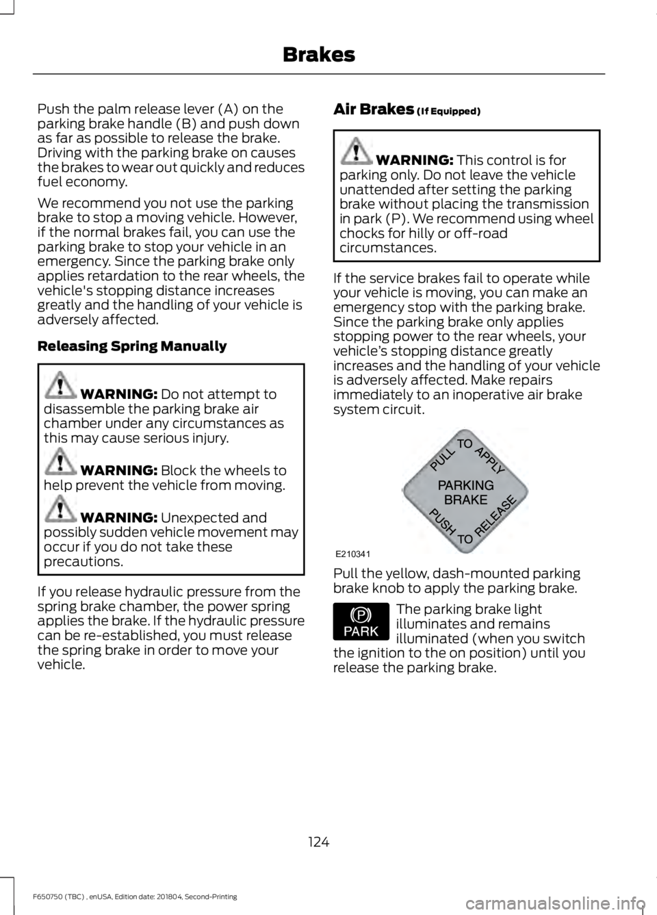
system circuit. Pull the yellow, dash-mounted parking
brake knob to apply the parking brake.
The parking brake light
illuminates and remains
illuminated (when you switch
the ignition to the on position) until you
release the parking brake.
124
F650750 (TBC) , enUSA, Edition date: 201804, Second-Printing BrakesE210341 E208810
Page 128 of 387
Releasing the Parking Brake
WARNING: When your vehicle is
stationary, keep the brake pedal fully
pressed when shifting gears. Failure to
follow this instruction could result in
personal injury, death or property
damage.
Note: Read and understand the following
steps and perform them whenever you
prepare to drive the vehicle.
Note: The parking brake does not disengage
unless sufficient system air pressure is
available.
1. Press and hold the service brake pedal
while the engine is running.
2. Select the appropriate drive gear.
3. Push and hold the yellow dash-mounted parking brake knob until
the parking brake light turns off, then
release.
Parking Brake Light Illumination Due
to Low Air Pressure
If the air pressure becomes too low at any
time during vehicle operation, the parking
brake may apply and the parking brake
light turns on.
If the parking brake applies due to low air
pressure, immediate service is required to
the parking brake system.
Releasing Spring Brake with Air
Pressure
The air system in all vehicles with
spring-actuated rear wheel parking brakes
has a valve on the governor for connection
to an outside air supply. The valve lets you
recharge the system with air from an
outside source, releasing the
spring-actuated parking brakes. Your
vehicle is now ready to tow in an
emergency. You can only use an outside air source if
the protected system is in operating
condition. If you cannot restore air pressure
in the protected air system, you must
release the spring-actuated brakes
manually.
Releasing Spring Manually
Do not use impact wrenches as they may
damage the piston and prevent proper
caging of the spring. Do not apply more
than
50 lb.ft (68 Nm) to the release bolt
nut.
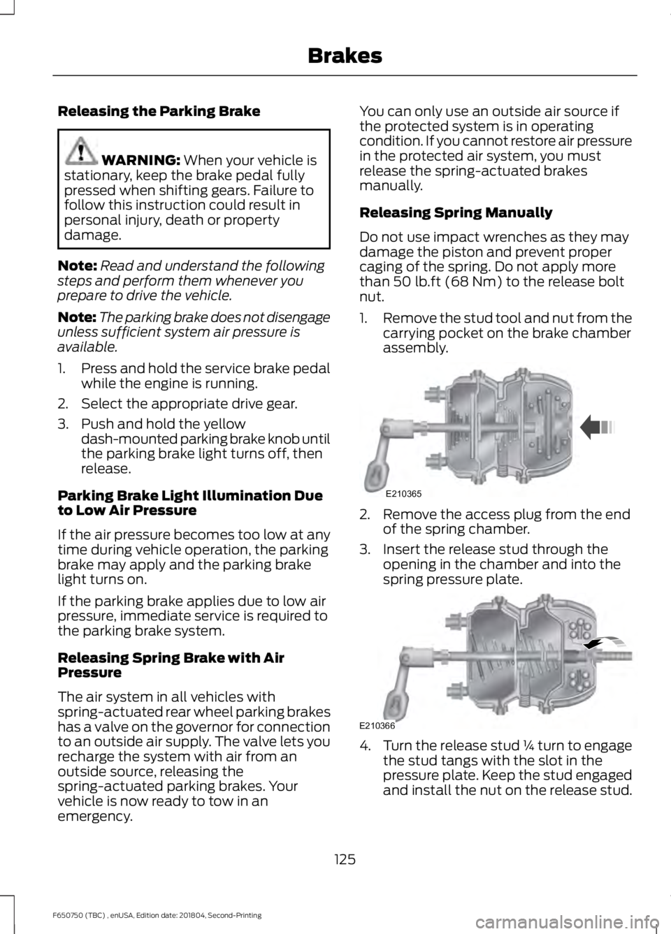
1. Remove the stud tool and nut from the
carrying pocket on the brake chamber
assembly. 2. Remove the access plug from the end
of the spring chamber.
3. Insert the release stud through the opening in the chamber and into the
spring pressure plate. 4.
Turn the release stud ¼ turn to engage
the stud tangs with the slot in the
pressure plate. Keep the stud engaged
and install the nut on the release stud.
125
F650750 (TBC) , enUSA, Edition date: 201804, Second-Printing BrakesE210365 E210366