cooling FORD F650/750 2019 Owners Manual
[x] Cancel search | Manufacturer: FORD, Model Year: 2019, Model line: F650/750, Model: FORD F650/750 2019Pages: 387, PDF Size: 4.78 MB
Page 12 of 387
If these modified engine performance
characteristics persist for an extended
period and either the service engine soon
or powertrain malfunction, reduced power,
electronic throttle control light is
illuminated, have the system checked by
an authorized dealer.
Service engine soon
Powertrain malfunction, reduced
power, electronic throttle control
Diesel Lubrication System
It is important to change the engine oil at
the recommended service intervals or
when indicated by the information display
to maintain oil viscosity. Extending the oil
and filter change interval beyond the
recommended interval can negatively
affect engine performance, fuel economy
and engine life. See Engine Oil Check
(page 192).
Engine and secondary cooling system
The cooling system contains a primary
cooling loop to cool the engine and a
secondary cooling loop to cool the
transmission, charge air, and fuel. The
coolant serves three primary purposes: to
provide heat transfer, freeze point
protection, and corrosion protection using
additives.
Vehicles with diesel engines typically are
used to carry heavy loads and accumulate
mileage rapidly. These two factors may
cause the additives in the coolant to wear
out in a shorter time. You can find more
information about coolant additives and
coolant change intervals in the coolant
chapter. See
General Maintenance
Information (page 322). Operating the
engine with insufficient coolant or coolant
additive can cause severe engine damage. Selective catalytic reduction system
Your vehicle is equipped with a selective
catalytic reduction system designed to
reduce emission levels of nitrogen oxides
from the exhaust of your diesel engine. This
system relies on the use of Diesel Exhaust
Fluid (DEF) that you must replenish at
certain intervals. Failure to maintain proper
DEF levels or if the DEF becomes
contaminated will result in vehicle speed
limitations or result in your vehicle entering
an idle-only mode. See
Selective
Catalytic Reductant System (page 105).
Minor Troubleshooting Guide
If the engine won ’t crank WARNING:
Battery posts,
terminals and related accessories
contain lead and lead compounds. Wash
hands after handling.
Turn on the headlights. If the lights are dim,
do not go on at all or when the ignition is
turned to the start position, the lights
become dim or go out, the battery
connections may be loose or corroded, or
the battery may be discharged. If there is
a clicking or stuttering sound coming from
the engine compartment when you turn
the key to the start position, this may also
indicate a loose or corroded battery
connection.
Check the battery connections at the
battery posts, cable connection to the
engine grounding point and at the starter
connection.
If you suspect a discharged battery, have
it checked and corrected.
9
F650750 (TBC) , enUSA, Edition date: 201804, Second-Printing Introduction
Page 13 of 387
•
The gearshift lever must be in P (Park)
or N (Neutral) in order for the starter
to operate.
• Try operating the starter switch several
times. This operation may clean
potentially corroded contacts or make
the switch temporarily operable until
you can reach the dealer.
• If all electrical connections are tight
and you need assistance to start, See
Jump Starting the Vehicle (page 156
).
If engine cranks but won ’t start
Prolonged starter cranking (in excess of 10
seconds) could cause damage to the
starter motor or the high-pressure fuel
pump.
• Check the fuel gauge. You may be out
of fuel. If the gauge shows that there
is fuel in the tank, the trouble may be
in the electrical system or the fuel
system. If equipped with an auxiliary
tank, be sure that the tank control
switch is set for the tank with fuel and
not on an empty tank.
• Leaving your ignition key turned to on
for over two minutes without starting
may make starting difficult because
the glow plugs will cease activation.
Reset the system by turning the ignition
key to off and then back to on again.
Note: If the system is out of fuel and the
engine will not start, do not continue
cranking the engine. Continued cranking can
damage the high-pressure fuel pump.
If the engine runs hot
The following could cause the engine to
overheat:
• Lack of coolant
• Dirty cooling system.
• Plugged radiator fins, A/C condenser
and/or oil cooler
• Malfunctioning fan drive •
Driving with frozen coolant
• Sticking thermostat
• Overloading or pulling heavy trailers
during hot weather
• Grill or radiator air blockage
• Slipping or missing drive belt
• Plugged or very dirty air filter
If fuses burn out WARNING:
Replacement fuses
and circuit breakers must always be the
same rating as the original equipment
shown. Never replace a fuse or circuit
breaker with one of a higher rating.
Higher rated fuses or circuit breakers
could allow circuit overloading in the
event of a circuit malfunction, resulting
in severe vehicle damage or personal
injury due to fire.
Burned-out or blown fuses usually indicate
an electrical short-circuit, although a fuse
may occasionally burn out from vibration.
Insert a second fuse. If this fuse
immediately burns out and you cannot
locate the cause, return your vehicle to
your dealer for a circuit check. See
Changing a Fuse
(page 176).
Selective catalytic reduction system
speed limit and Idle-only modes
If the vehicle ’s speed is limited or in an
idle-only mode, the selective catalytic
reduction system may be limiting the
vehicle ’s functions due to low or
contaminated DEF. Check the DEF. See
Selective Catalytic Reductant System
(page
105).
SYMBOLS GLOSSARY
These are some of the symbols you may
see on your vehicle.
10
F650750 (TBC) , enUSA, Edition date: 201804, Second-Printing Introduction
Page 19 of 387
PROTECTING THE
ENVIRONMENT
You should play your part in protecting the
environment. Correct vehicle usage and
the authorized disposal of waste, cleaning
and lubrication materials are significant
steps toward this aim.
For details about Ford Motor
Company's sustainability progress and
initiatives visit:
Web Address
www.sustainability.ford.com
NOISE POLLUTION CONTROL
In order to keep to the federal exterior
noise regulations, your vehicle may be
equipped with noise emission items.
Depending on your vehicle configuration,
it may have all or some of the following
items:
Air Intake System
Inspect the air cleaner. Do not alter its
location. Do not alter inlet and outlet
piping.
Body
Inspect wheel well splash shields, cab
shields and under hood insulation for
deterioration, dislocation and orientation.
Cooling System
• Inspect the fan for blade damage. If
you find any damage, replace with the
recommended parts. Inspect for
fan-to-shroud interference and any
damage to shroud, such as cracks and
holes.
• Do not change fan ratio or alter fan
spacer dimensions and positions. •
Inspect fan clutch for proper operation.
Make sure the fan is disengaged when
cooling of the engine is not required.
• Inspect radiator shutters (if equipped)
for proper operation. The shutters
should be open during normal
operating temperatures.
Engine
Valve covers and block covers damp-out
engine mechanical noise. If they need
replacing, make sure to replace them with
the recommended parts. Check for
mechanical isolations.
Transmission Enclosure
Inspect for cracks, holes and tears. Clean
any deposits, such as oil, dirt and stones.
Exhaust System
• Inspect for leaks at various joint
connections and loose clamps.
• Perform a visual inspection for cracks
or holes in the muffler and tail pipe.
• Always use the recommended
replacement parts.
• Do not change the tail pipe elbow or
offset tail pipe orientation from the
standard position as originally received.
• To avoid abnormal changes in vehicle
sound levels, it is necessary for the
owner to perform inspections and
necessary maintenance at specified
intervals. See Scheduled
Maintenance (page 322).
16
F650750 (TBC) , enUSA, Edition date: 201804, Second-Printing Environment
Page 75 of 387
MANUAL CLIMATE CONTROL
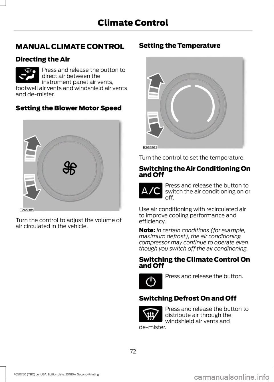
Directing the Air
Press and release the button to
direct air between the
instrument panel air vents,
footwell air vents and windshield air vents
and de-mister.
Setting the Blower Motor Speed Turn the control to adjust the volume of
air circulated in the vehicle. Setting the Temperature Turn the control to set the temperature.
Switching the Air Conditioning On
and Off
Press and release the button to
switch the air conditioning on or
off.
Use air conditioning with recirculated air
to improve cooling performance and
efficiency.
Note: In certain conditions (for example,
maximum defrost), the air conditioning
compressor may continue to operate even
though you switch off the air conditioning.
Switching the Climate Control On
and Off Press and release the button.
Switching Defrost On and Off Press and release the button to
distribute air through the
windshield air vents and
de-mister.
72
F650750 (TBC) , enUSA, Edition date: 201804, Second-Printing Climate ControlE265283 E265389 E265862
Page 76 of 387
Air directed to the instrument panel and
footwell air vents turns off. You can also
use this setting to defog and clear the
windshield of a thin covering of ice.
Switching Maximum Air
Conditioning On and Off
Press and release the button for
maximum cooling.
The left-hand and right-hand settings set
to LO, recirculated air flows through the
instrument panel air vents, air conditioning
turns on and the blower motor adjusts to
the highest speed.
Switching Recirculated Air On and
Off Press and release the button to
switch between outside air and
recirculated air.
The air currently in the passenger
compartment recirculates. This may
reduce the time needed to cool the interior
(when used with A/C) and reduce
unwanted odors from entering your vehicle.
Note: Recirculated air may turn off (or
prevent you from switching on) in all air flow
modes except MAX A/C to reduce the risk
of fogging. Recirculation may also turn on
and off in various air distribution control
combinations during hot weather in order
to improve cooling efficiency.
HINTS ON CONTROLLING THE
INTERIOR CLIMATE
General Hints
Note: Prolonged use of recirculated air may
cause the windows to fog up.
Note: You may feel a small amount of air
from the footwell air vents regardless of the
air distribution setting. Note:
To reduce humidity build-up inside
your vehicle, do not drive with the system
switched off or with recirculated air always
switched on.
Note: Do not place objects under the front
seats as this may interfere with the airflow
to the rear seats.
Note: Remove any snow, ice or leaves from
the air intake area at the base of the
windshield.
Note: To improve the time to reach a
comfortable temperature in hot weather,
drive with the windows open until you feel
cold air through the air vents.
Quickly Heating the Interior
1. Adjust the blower motor speed to the highest speed setting.
2. Adjust the temperature control to the highest setting.
3. Direct air to the footwell air vents.
Recommended Settings for
Heating
1. Adjust the blower motor speed to the center setting.
2. Adjust the temperature control to the midway point of the hot settings.
3. Direct air to the footwell air vents.
Quickly Cooling the Interior
1. Select MAX A/C.
2. Drive with the windows open for a short
period of time.
Recommended Settings for
Cooling
1. Adjust the blower motor speed to the center setting.
2. Adjust the temperature control to the midway point of the cold settings.
73
F650750 (TBC) , enUSA, Edition date: 201804, Second-Printing Climate Control
Page 116 of 387
Once operator commanded regeneration
starts, engine speed increases to
approximately 2000 rpm and the cooling
fan speed increases. You will hear a
change in audible sound due to engine
speed and cooling fan speed increases.
It is not necessary to open the hood on the
engine compartment. Once operator
commanded regeneration completes, the
engine speed returns to normal idling. The
exhaust system remains very hot for
several minutes even after regeneration is
complete. Do not reposition the vehicle
over materials that could burn until the
exhaust system has had sufficient time to
cool. Depending on the amount of soot
collected by the diesel particulate filter,
ambient temperature and altitude,
operator commanded regeneration lasts
approximately 30 minutes.
Operator Commanded Regeneration
with Automatic Regeneration Control
(If Equipped)
If your vehicle is operated with significant
stationary operation, low speed drive
cycles less than 25 mph (40 km/h), short
drive cycles, drive time less than 15 minutes
or the vehicle does not fully warm up,
passive and active regeneration may not
sufficiently clean the diesel particulate
filter system. You can switch off automatic
regeneration until better driving conditions
are available, for example steady high
speed driving. You can then switch
automatic regeneration back on to clean
the diesel particulate filter.
Switching Automatic Regeneration
Control On and Off
To switch operator commanded
regeneration on and off, use the
information display control on the steering
wheel. See Information Display Control
(page
47). Scroll to the exhaust cleaning
message and then select Y or N to switch
it On or Off. How to Interrupt or Cancel Operator
Commanded Regeneration
If you need to cancel the operator
commanded regeneration, pressing the
brake, accelerator or switching the engine
off stops the procedure. Depending on the
amount of time you allowed the operator
commanded regeneration to operate, soot
may not have had sufficient time to be fully
eliminated, but the exhaust system and
exhaust gas may still be hot. If you shut
your vehicle off during operator
commanded regeneration, you may notice
turbo flutter. This is a normal consequence
caused by shutting off a diesel engine
during boosted operation and is considered
normal.
Filter Service and Maintenance
Over time, a slight amount of ash builds
up in the diesel particulate filter, which is
not removed during the regeneration
process. The filter may need to be replaced
with a new or remanufactured part at
approximately 250,000 mi (400,000 km).
Actual mileage varies depending on engine
and vehicle operating conditions.
If filter service is required, the
engine control system warning
lamp illuminates in the
information display. If there are any issues with the
diesel particulate filter system,
the engine control system
warning lamp and a service
engine soon warning lamp
illuminate to inform you that
your vehicle requires service. Have your
vehicle checked as soon as possible.
113
F650750 (TBC) , enUSA, Edition date: 201804, Second-Printing Engine Emission Control
Page 122 of 387
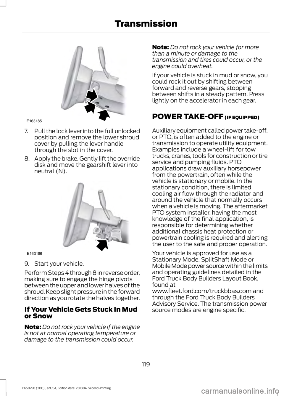
7.
Pull the lock lever into the full unlocked
position and remove the lower shroud
cover by pulling the lever handle
through the slot in the cover.
8. Apply the brake. Gently lift the override
disk and move the gearshift lever into
neutral (N). 9. Start your vehicle.
Perform Steps 4 through 8 in reverse order,
making sure to engage the hinge pivots
between the upper and lower halves of the
shroud. Keep slight pressure in the forward
direction as you rotate the halves together.
If Your Vehicle Gets Stuck In Mud
or Snow
Note:
Do not rock your vehicle if the engine
is not at normal operating temperature or
damage to the transmission could occur. Note:
Do not rock your vehicle for more
than a minute or damage to the
transmission and tires could occur, or the
engine could overheat.
If your vehicle is stuck in mud or snow, you
could rock it out by shifting between
forward and reverse gears, stopping
between shifts in a steady pattern. Press
lightly on the accelerator in each gear.
POWER TAKE-OFF (IF EQUIPPED)
Auxiliary equipment called power take-off,
or PTO, is often added to the engine or
transmission to operate utility equipment.
Examples include a wheel-lift for tow
trucks, cranes, tools for construction or tire
service and pumping fluids. PTO
applications draw auxiliary horsepower
from the powertrain, often while the
vehicle is stationary or mobile. In the
stationary condition, there is limited
cooling air flow through the radiator and
around the vehicle that normally occurs
when a vehicle is moving. The aftermarket
PTO system installer, having the most
knowledge of the final application, is
responsible for determining whether
additional chassis heat protection or
powertrain cooling is required and alerting
the user to the safe and proper operation.
Your vehicle is approved for use as a
Stationary Mode, SplitShaft Mode or
Mobile Mode power source within the limits
and operating guidelines detailed in the
Ford Truck Body Builders Layout Book,
found at
www.fleet.ford.com/truckbbas.com and
through the Ford Truck Body Builders
Advisory Service. The transmission power
source modes are engine specific.
119
F650750 (TBC) , enUSA, Edition date: 201804, Second-Printing TransmissionE163185 E163186
Page 149 of 387
ESSENTIAL TOWING CHECKS
See Load limits in the Load Carrying
chapter for load specification terms found
on the tire label and Safety Compliance
label and instructions on calculating your
vehicle's load.
Remember to account for the trailer
tongue weight as part of your vehicle load
when calculating the total vehicle weight.
Hitches
Do not use a hitch that either clamps onto
the bumper or attaches to the axle. You
must distribute the load in your trailer so
that 10-15% of the total weight of the
trailer is on the tongue.
Safety Chains
Note: Do not attach safety chains to the
bumper.
Always connect the safety chains to the
frame or hook retainers of your vehicle
hitch.
To connect the safety chains, cross the
chains under the trailer tongue and allow
enough slack for turning tight corners. Do
not allow the chains to drag on the ground.
Trailer Brakes WARNING:
Do not connect a
trailer's hydraulic brake system directly
to your vehicle's brake system. Your
vehicle may not have enough braking
power and your chances of having a
collision greatly increase.
Electric brakes and manual, automatic or
surge-type trailer brakes are safe if you
install them properly and adjust them to
the manufacturer's specifications. The
trailer brakes must meet local and federal
regulations. The rating for the tow vehicle's braking
system operation is at the gross vehicle
weight rating, not the gross combined
weight rating.
Trailer Lamps
WARNING:
Never connect any
trailer lamp wiring to the vehicle's tail
lamp wiring; this may damage the
electrical system resulting in fire. Contact
your authorized dealer as soon as
possible for assistance in proper trailer
tow wiring installation. Additional
electrical equipment may be required.
Trailer lamps are required on most towed
vehicles. Make sure all running lights, brake
lights, turn signals and hazard lights are
working.
Before Towing a Trailer
Practice turning, stopping and backing up
to get the feel of your vehicle-trailer
combination before starting on a trip.
When turning, make wider turns so the
trailer wheels clear curbs and other
obstacles.
When Towing a Trailer
• Check your hitch, electrical connections
and trailer wheel lug nuts thoroughly
after you have traveled
50 mph
(80 km/h).
• When stopped in congested or heavy
traffic during hot weather, place the
transmission in park (P) or neutral (N)
to aid engine and transmission cooling
and to help air conditioning
performance.
• Turn off the speed control with heavy
loads or in hilly terrain. The speed
control may turn off automatically
when you are towing on long, steep
grades.
146
F650750 (TBC) , enUSA, Edition date: 201804, Second-Printing Towing
Page 150 of 387
•
Shift to a lower gear when driving down
a long or steep hill. Do not apply the
brakes continuously, as they may
overheat and become less effective.
• If your transmission is equipped with
the Tow/Haul feature, use this feature
when towing. This provides engine
braking and helps eliminate excessive
transmission shifting for optimum fuel
economy and transmission cooling.
• Allow more distance for stopping with
a trailer attached. Anticipate stops and
brake gradually.
FIFTH WHEEL OPERATION WARNING: Failure to follow the
fifth wheel manufacturer ’s instructions
for hooking and unhooking as well as
sliding the fifth wheel could result in an
accident, personal injury or death. WARNING:
When the tractor and
trailer are parked unattended, the trailer
brake hand control should never be used
to apply the brake, since air may leak
from the system, allowing vehicle
movement, resulting in possible property
damage, personal injury or death.
Before hook-up, make sure:
• The fifth wheel jaws are fully open.
• The fifth wheel is fully tilted back to
prevent body damage when the tractor
is backed under a trailer.
• You block the trailer wheels and adjust
and apply the trailer spring brakes.
Never chase a trailer.
• The brake hoses and light cords are
clear of the fifth wheel. Hook-up
1. Back the tractor squarely under the
trailer, engaging the fifth-wheel jaws
on the kingpin. Always back up slowly;
make sure the trailer is neither too high
nor too low. Avoid backing under the
trailer from an angle.
2. Connect the service and emergency brake hoses and trailer light connector.
3. Inspect the jaws of the fifth wheel to be sure they have fully closed on the
trailer kingpin and the trailer plate is
resting securely on the fifth wheel.
4. Make sure the coupler release lever is in the locked position.
5. Charge the trailer brake system. Set the trailer brakes, with either the hand
valve or tractor protection valve. Pull
against the trailer for an extra check of
proper hook-up. Do not pull hard
enough to damage or strain the
equipment.
6. Set the tractor parking brakes and fully
raise the trailer landing gear.
7. Check the operation of all trailer lights
and correct any lights that may be
faulty.
Un-hook
1. Try to keep the tractor and trailer in a straight line.
2. Apply the parking brakes.
3. Lower the trailer landing gear, making sure it is on solid, level ground. The
weight of the trailer is to be on the
landing gear.
4. Block the trailer wheels.
5. Disconnect the brake hoses and light cords. Be sure hoses and cords are
clear.
6. Pull coupler release lever to disengage
the fifth wheel jaws.
147
F650750 (TBC) , enUSA, Edition date: 201804, Second-Printing Towing
Page 155 of 387
In order to operate the engine in
temperatures of 32°F (0°C) or lower, read
the following instructions:
•
Make sure that the batteries are of
sufficient size and are fully charged.
Check other electrical components to
make sure they are in optimum
condition
• Use the proper coolant solution at the
concentration recommended
protecting the engine against damage
from freezing
• Try to keep the fuel tank full as much
as possible at the end of operation to
prevent condensation in the fuel
system
• Make sure you use proper cold weather
engine oil and that it is at its proper
level. Also, if necessary, make sure to
follow the engine oil and filter change
schedule found under the Special
operating conditions section listed in
the scheduled maintenance
information
• At temperatures of -9°F (-23°C) or
below, it is recommended that you use
an engine block heater to improve cold
engine starting
• If operating in arctic temperatures of
-20°F (-29°C)
or lower, consult your
truck dealer for information about
special cold weather equipment and
precautions
The following cold weather idling
guidelines are recommended:
• You can use Motorcraft® cetane
improvers or non-alcohol-based
cetane improvers from a reputable
manufacturer as needed.
• Maintain the engine cooling system
properly. •
Avoid shutting the engine down after
an extensive idling period. Drive your
vehicle for several miles with the
engine at normal operating
temperatures under a moderate load.
• Consider using an engine block heater.
• For extended idle times use an
approved idle speed increase device.
Winter Operating Tips for Arctic
Operation -20°F (-29°C) and
Below
The following information is a guideline
only and is not to be the only source of
possible solutions in resolving extreme
cold temperature issues.
Starting Aids WARNING:
Do not use starting
fluid, such as ether, in the air intake
system (see air filter decal). Such fluid
could cause immediate explosive
damage to the engine and possible
personal injury.
The use of the factory engine block heater
assists in engine starting in extreme cold
ambient temperatures. See
Engine Block
Heater (page 90).
Idle Control
Your vehicle may have a factory option for
a stationary elevated idle control through
dash-mounted upfitter switches that
allows the operator to elevate the idle rpm
for extended idle periods, as well as
aftermarket equipment such as PTO
operation. You must configure this feature
even if ordered from the factory. See your
authorized dealer for required upfitting.
152
F650750 (TBC) , enUSA, Edition date: 201804, Second-Printing Driving Hints