maintenance reset FORD F650/750 2021 Owners Manual
[x] Cancel search | Manufacturer: FORD, Model Year: 2021, Model line: F650/750, Model: FORD F650/750 2021Pages: 390, PDF Size: 5.16 MB
Page 7 of 390
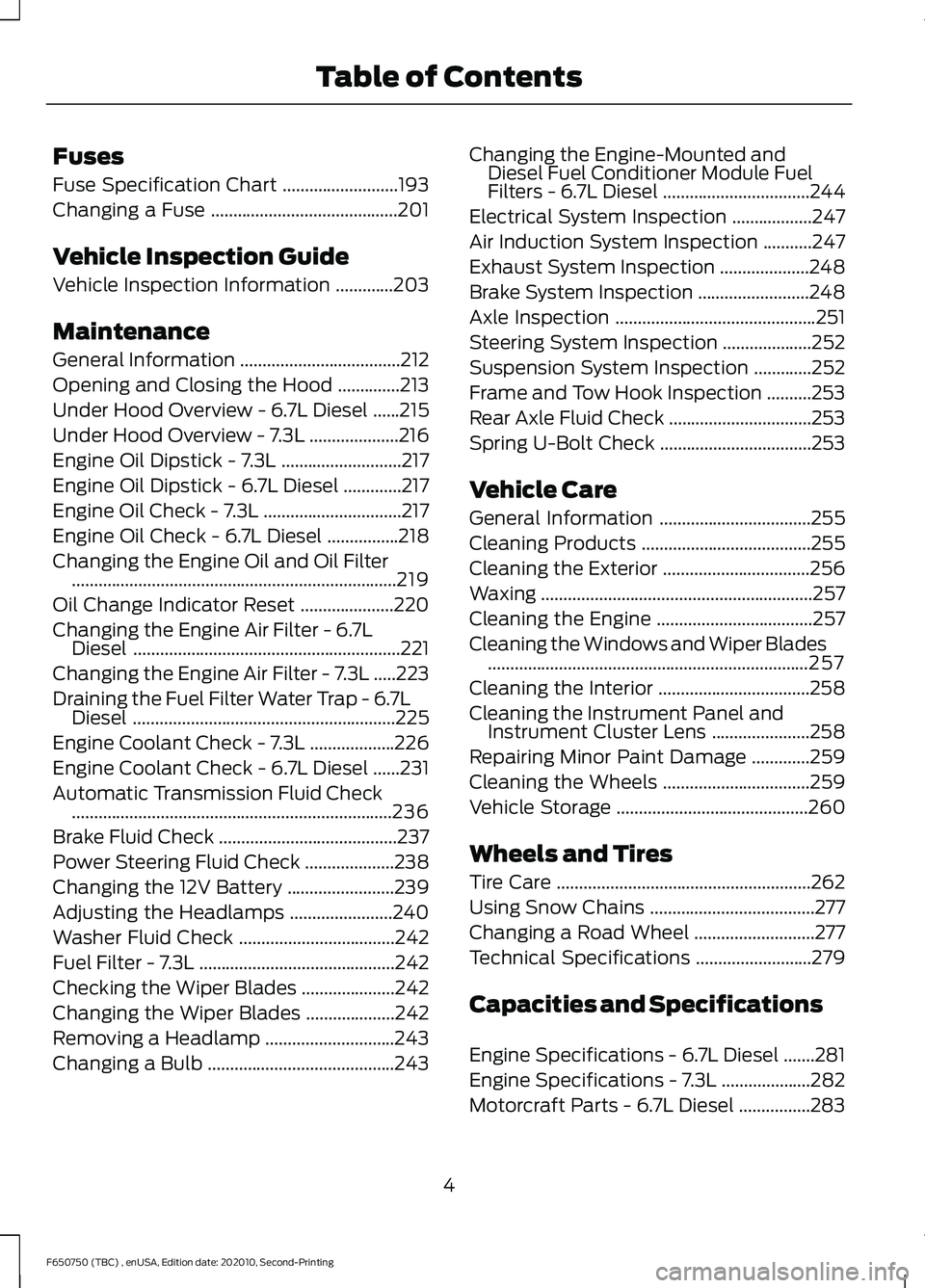
Fuses
Fuse Specification Chart
..........................193
Changing a Fuse ..........................................
201
Vehicle Inspection Guide
Vehicle Inspection Information .............
203
Maintenance
General Information ....................................
212
Opening and Closing the Hood ..............
213
Under Hood Overview - 6.7L Diesel ......
215
Under Hood Overview - 7.3L ....................
216
Engine Oil Dipstick - 7.3L ...........................
217
Engine Oil Dipstick - 6.7L Diesel .............
217
Engine Oil Check - 7.3L ...............................
217
Engine Oil Check - 6.7L Diesel ................
218
Changing the Engine Oil and Oil Filter ........................................................................\
.
219
Oil Change Indicator Reset .....................
220
Changing the Engine Air Filter - 6.7L Diesel ............................................................
221
Changing the Engine Air Filter - 7.3L .....
223
Draining the Fuel Filter Water Trap - 6.7L Diesel ...........................................................
225
Engine Coolant Check - 7.3L ...................
226
Engine Coolant Check - 6.7L Diesel ......
231
Automatic Transmission Fluid Check ........................................................................\
236
Brake Fluid Check ........................................
237
Power Steering Fluid Check ....................
238
Changing the 12V Battery ........................
239
Adjusting the Headlamps .......................
240
Washer Fluid Check ...................................
242
Fuel Filter - 7.3L ............................................
242
Checking the Wiper Blades .....................
242
Changing the Wiper Blades ....................
242
Removing a Headlamp .............................
243
Changing a Bulb ..........................................
243Changing the Engine-Mounted and
Diesel Fuel Conditioner Module Fuel
Filters - 6.7L Diesel .................................
244
Electrical System Inspection ..................
247
Air Induction System Inspection ...........
247
Exhaust System Inspection ....................
248
Brake System Inspection .........................
248
Axle Inspection .............................................
251
Steering System Inspection ....................
252
Suspension System Inspection .............
252
Frame and Tow Hook Inspection ..........
253
Rear Axle Fluid Check ................................
253
Spring U-Bolt Check ..................................
253
Vehicle Care
General Information ..................................
255
Cleaning Products ......................................
255
Cleaning the Exterior .................................
256
Waxing .............................................................
257
Cleaning the Engine ...................................
257
Cleaning the Windows and Wiper Blades ........................................................................\
257
Cleaning the Interior ..................................
258
Cleaning the Instrument Panel and Instrument Cluster Lens ......................
258
Repairing Minor Paint Damage .............
259
Cleaning the Wheels .................................
259
Vehicle Storage ...........................................
260
Wheels and Tires
Tire Care .........................................................
262
Using Snow Chains .....................................
277
Changing a Road Wheel ...........................
277
Technical Specifications ..........................
279
Capacities and Specifications
Engine Specifications - 6.7L Diesel .......
281
Engine Specifications - 7.3L ....................
282
Motorcraft Parts - 6.7L Diesel ................
283
4
F650750 (TBC) , enUSA, Edition date: 202010, Second-Printing Table of Contents
Page 16 of 390
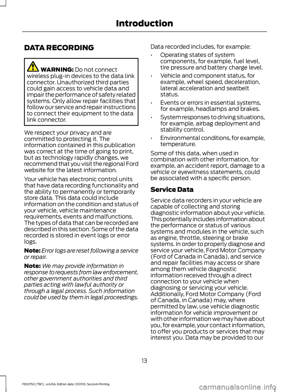
DATA RECORDING
WARNING: Do not connect
wireless plug-in devices to the data link
connector. Unauthorized third parties
could gain access to vehicle data and
impair the performance of safety related
systems. Only allow repair facilities that
follow our service and repair instructions
to connect their equipment to the data
link connector.
We respect your privacy and are
committed to protecting it. The
information contained in this publication
was correct at the time of going to print,
but as technology rapidly changes, we
recommend that you visit the regional Ford
website for the latest information.
Your vehicle has electronic control units
that have data recording functionality and
the ability to permanently or temporarily
store data. This data could include
information on the condition and status of
your vehicle, vehicle maintenance
requirements, events and malfunctions.
The types of data that can be recorded are
described in this section. Some of the data
recorded is stored in event logs or error
logs.
Note: Error logs are reset following a service
or repair.
Note: We may provide information in
response to requests from law enforcement,
other government authorities and third
parties acting with lawful authority or
through a legal process. Such information
could be used by them in legal proceedings. Data recorded includes, for example:
•
Operating states of system
components, for example, fuel level,
tire pressure and battery charge level.
• Vehicle and component status, for
example, wheel speed, deceleration,
lateral acceleration and seatbelt
status.
• Events or errors in essential systems,
for example, headlamps and brakes.
• System responses to driving situations,
for example, airbag deployment and
stability control.
• Environmental conditions, for example,
temperature.
Some of this data, when used in
combination with other information, for
example, an accident report, damage to a
vehicle or eyewitness statements, could
be associated with a specific person.
Service Data
Service data recorders in your vehicle are
capable of collecting and storing
diagnostic information about your vehicle.
This potentially includes information about
the performance or status of various
systems and modules in the vehicle, such
as engine, throttle, steering or brake
systems. In order to properly diagnose and
service your vehicle, Ford Motor Company
(Ford of Canada in Canada), and service
and repair facilities may access or share
among them vehicle diagnostic
information received through a direct
connection to your vehicle when
diagnosing or servicing your vehicle.
Additionally, Ford Motor Company (Ford
of Canada, in Canada) may, where
permitted by law, use vehicle diagnostic
information for vehicle improvement or
with other information we may have about
you, for example, your contact information,
to offer you products or services that may
interest you. Data may be provided to our
13
F650750 (TBC) , enUSA, Edition date: 202010, Second-Printing Introduction
Page 74 of 390
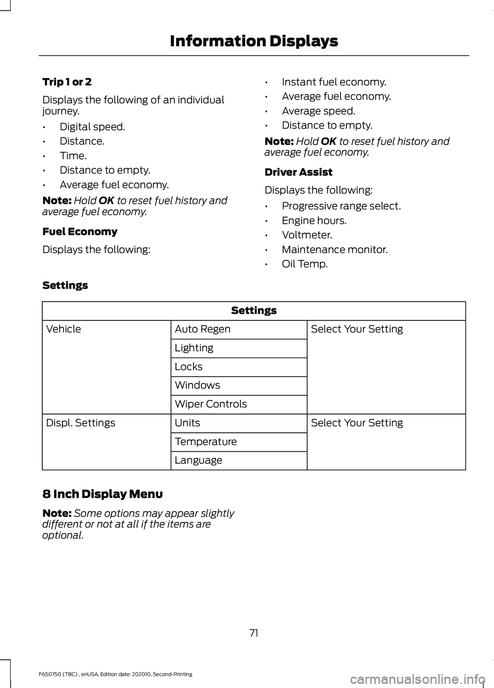
Trip 1 or 2
Displays the following of an individual
journey.
•
Digital speed.
• Distance.
• Time.
• Distance to empty.
• Average fuel economy.
Note: Hold OK to reset fuel history and
average fuel economy.
Fuel Economy
Displays the following: •
Instant fuel economy.
• Average fuel economy.
• Average speed.
• Distance to empty.
Note: Hold
OK to reset fuel history and
average fuel economy.
Driver Assist
Displays the following:
• Progressive range select.
• Engine hours.
• Voltmeter.
• Maintenance monitor.
• Oil Temp.
Settings Settings
Select Your Setting
Auto Regen
Vehicle
Lighting
Locks
Windows
Wiper Controls Select Your Setting
Units
Displ. Settings
Temperature
Language
8 Inch Display Menu
Note: Some options may appear slightly
different or not at all if the items are
optional.
71
F650750 (TBC) , enUSA, Edition date: 202010, Second-Printing Information Displays
Page 76 of 390
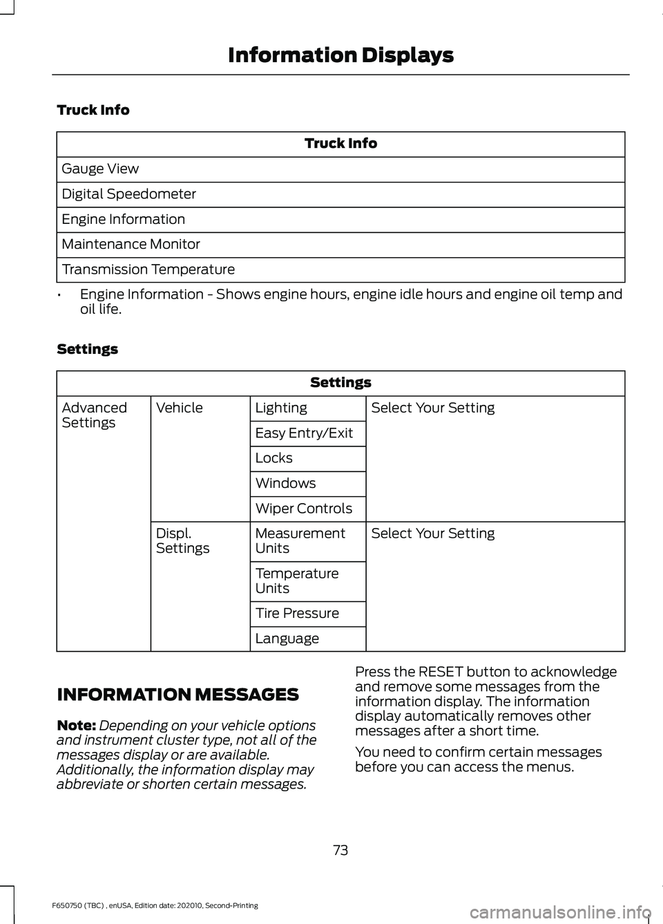
Truck Info
Truck Info
Gauge View
Digital Speedometer
Engine Information
Maintenance Monitor
Transmission Temperature
• Engine Information - Shows engine hours, engine idle hours and engine oil temp and
oil life.
Settings Settings
Select Your Setting
Lighting
Vehicle
Advanced
Settings
Easy Entry/Exit
Locks
Windows
Wiper Controls
Select Your Setting
Measurement
Units
Displ.
Settings
Temperature
Units
Tire Pressure
Language
INFORMATION MESSAGES
Note: Depending on your vehicle options
and instrument cluster type, not all of the
messages display or are available.
Additionally, the information display may
abbreviate or shorten certain messages. Press the RESET button to acknowledge
and remove some messages from the
information display. The information
display automatically removes other
messages after a short time.
You need to confirm certain messages
before you can access the menus.
73
F650750 (TBC) , enUSA, Edition date: 202010, Second-Printing Information Displays
Page 223 of 390
5. For diesel engines, you need to reset
the Intelligent Oil Life Monitor™. See
Information Displays (page 70).
Engine lubrication for severe
service operation
The following conditions define severe
operation for which engine operation with
SAE 5W-40 API CJ-4 is recommended. Oil
and oil filter change intervals will be
determined by the Intelligent Oil Life
Monitor™ as noted previously.
• Frequent or extended idling (over 10
minutes per hour of normal driving).
• Low-speed operation/stationary use.
• If vehicle is operated in sustained
ambient temperatures below
-9°F
(-23°C) or above 100°F (38°C).
• Frequent low-speed operation,
consistent heavy traffic less than
25 mph (40 km/h)
.
• Operating in severe dust conditions.
• Operating the vehicle off road.
• Towing a trailer over
1,000 mi
(1,600 km).
• Sustained, high-speed driving at Gross
Vehicle Weight Rating (maximum
loaded weight for vehicle operation).
• Use of fuels with sulfur content other
than ultra-low sulfur diesel (ULSD).
• Use of high-sulfur diesel fuel.
OIL CHANGE INDICATOR
RESET
Base Cluster
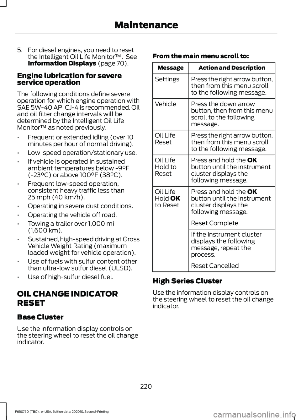
Use the information display controls on
the steering wheel to reset the oil change
indicator. From the main menu scroll to: Action and Description
Message
Press the right arrow button,
then from this menu scroll
to the following message.
Settings
Press the down arrow
button, then from this menu
scroll to the following
message.
Vehicle
Press the right arrow button,
then from this menu scroll
to the following message.
Oil Life
Reset
Press and hold the
OK
button until the instrument
cluster displays the
following message.
Oil Life
Hold to
Reset
Press and hold the
OK
button until the instrument
cluster displays the
following message.
Oil Life
Hold OK
to Reset
Reset Complete
If the instrument cluster
displays the following
message, repeat the
process.
Reset Cancelled
High Series Cluster
Use the information display controls on
the steering wheel to reset the oil change
indicator.
220
F650750 (TBC) , enUSA, Edition date: 202010, Second-Printing Maintenance
Page 224 of 390
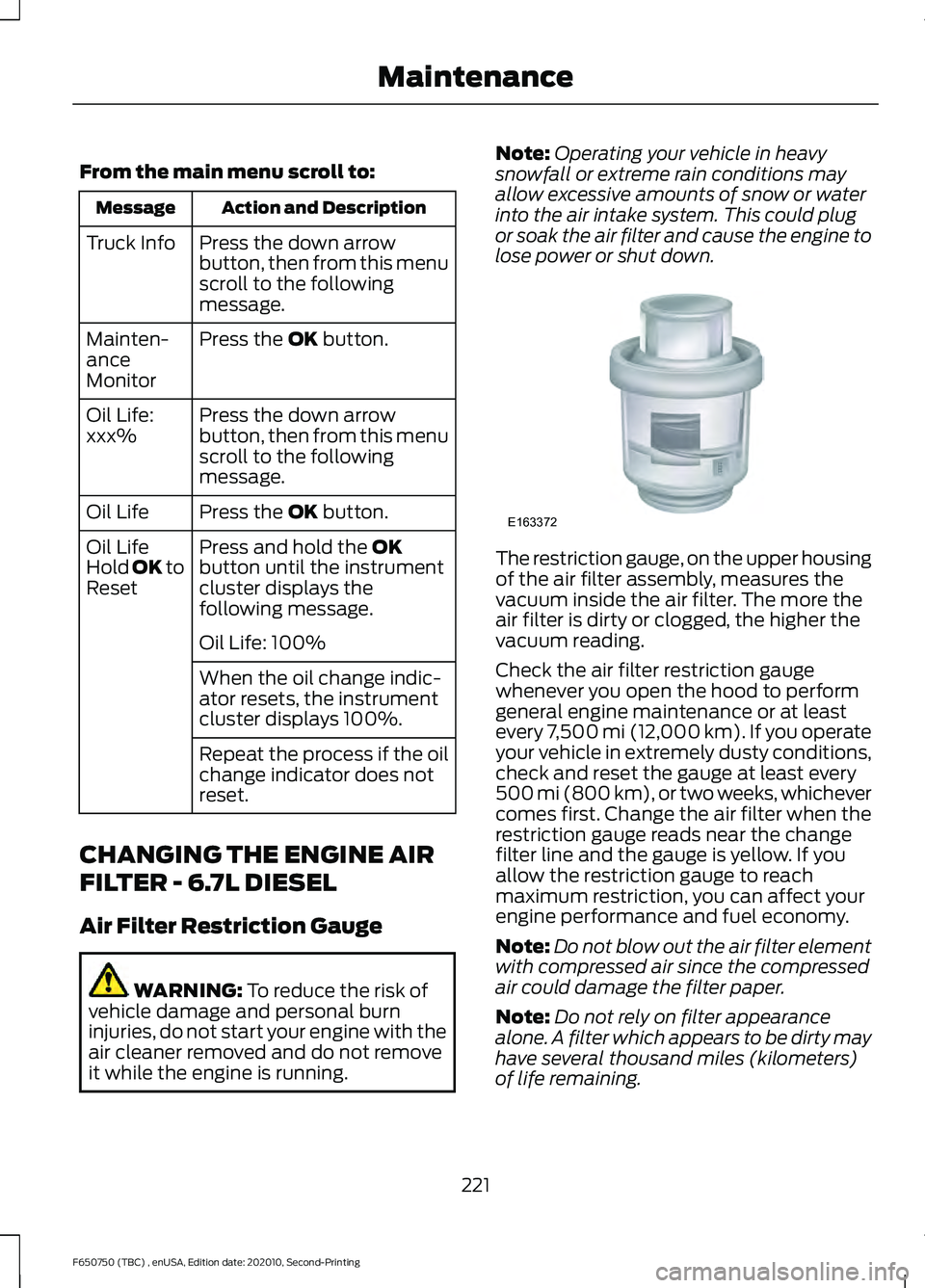
From the main menu scroll to:
Action and Description
Message
Press the down arrow
button, then from this menu
scroll to the following
message.
Truck Info
Press the OK button.
Mainten-
ance
Monitor
Press the down arrow
button, then from this menu
scroll to the following
message.
Oil Life:
xxx%
Press the
OK button.
Oil Life
Press and hold the
OK
button until the instrument
cluster displays the
following message.
Oil Life
Hold OK to
Reset
Oil Life: 100%
When the oil change indic-
ator resets, the instrument
cluster displays 100%.
Repeat the process if the oil
change indicator does not
reset.
CHANGING THE ENGINE AIR
FILTER - 6.7L DIESEL
Air Filter Restriction Gauge WARNING:
To reduce the risk of
vehicle damage and personal burn
injuries, do not start your engine with the
air cleaner removed and do not remove
it while the engine is running. Note:
Operating your vehicle in heavy
snowfall or extreme rain conditions may
allow excessive amounts of snow or water
into the air intake system. This could plug
or soak the air filter and cause the engine to
lose power or shut down. The restriction gauge, on the upper housing
of the air filter assembly, measures the
vacuum inside the air filter. The more the
air filter is dirty or clogged, the higher the
vacuum reading.
Check the air filter restriction gauge
whenever you open the hood to perform
general engine maintenance or at least
every 7,500 mi (12,000 km). If you operate
your vehicle in extremely dusty conditions,
check and reset the gauge at least every
500 mi (800 km), or two weeks, whichever
comes first. Change the air filter when the
restriction gauge reads near the change
filter line and the gauge is yellow. If you
allow the restriction gauge to reach
maximum restriction, you can affect your
engine performance and fuel economy.
Note:
Do not blow out the air filter element
with compressed air since the compressed
air could damage the filter paper.
Note: Do not rely on filter appearance
alone. A filter which appears to be dirty may
have several thousand miles (kilometers)
of life remaining.
221
F650750 (TBC) , enUSA, Edition date: 202010, Second-Printing MaintenanceE163372
Page 225 of 390
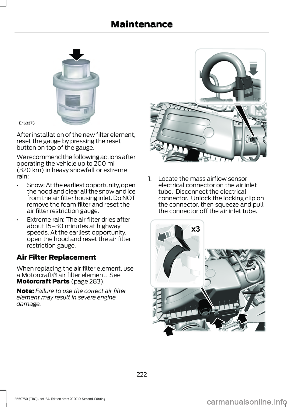
After installation of the new filter element,
reset the gauge by pressing the reset
button on top of the gauge.
We recommend the following actions after
operating the vehicle up to 200 mi
(320 km) in heavy snowfall or extreme
rain:
• Snow: At the earliest opportunity, open
the hood and clear all the snow and ice
from the air filter housing inlet. Do NOT
remove the foam filter and reset the
air filter restriction gauge.
• Extreme rain: The air filter dries after
about 15– 30 minutes at highway
speeds. At the earliest opportunity,
open the hood and reset the air filter
restriction gauge.
Air Filter Replacement
When replacing the air filter element, use
a Motorcraft® air filter element. See
Motorcraft Parts
(page 283).
Note: Failure to use the correct air filter
element may result in severe engine
damage. 1. Locate the mass airflow sensor
electrical connector on the air inlet
tube. Disconnect the electrical
connector. Unlock the locking clip on
the connector, then squeeze and pull
the connector off the air inlet tube. 222
F650750 (TBC) , enUSA, Edition date: 202010, Second-Printing MaintenanceE163373 E317651 x3E317652
Page 232 of 390
Coolant Change
Change the coolant at specific mileage
intervals as listed in the scheduled
maintenance information. The information
display may display a message to change
coolant at this time. Add prediluted
coolant approved to the correct
specification. See Capacities and
Specifications (page 281).
Engine-driven Cooling Fan (Fan
Clutch)
Your vehicle comes with an engine driven
cooling fan drive, also called a fan clutch.
This fan drive changes the fan speed to
match the vehicle ’s changing cooling air
flow requirements. Fan speed, fan noise
level and fuel consumption all will increase
based on the driving conditions that
include trailer towing, hill climbing, heavy
loads, high speed and high ambient
temperature, individually or in combination.
The fan drive is designed to provide the
minimum fan speed, and resulting
minimum fan noise and fuel consumption
required to meet the ever changing vehicle
cooling air flow requirements. You will hear
the amount of fan noise increasing and
decreasing as the engine power
requirements and vehicle driving conditions
change as you drive. This is to be expected
as being normal to the operation of your
vehicle. High levels of fan noise might also
be heard when your engine is first started,
and should normally decrease after driving
for a short time.
Fail-Safe Cooling
Fail-safe cooling allows you to temporarily
drive your vehicle before any incremental
component damage occurs. The fail-safe
distance depends on ambient
temperature, vehicle load and terrain. How Fail-Safe Cooling Works
If the engine begins to overheat, the
coolant temperature gauge moves toward
the red zone: A warning lamp illuminates and
a message may appear in the
information display.
If the engine reaches a preset
over-temperature condition, the engine
switches to alternating cylinder operation.
Each disabled cylinder acts as an air pump
and cools the engine.
When this occurs, your vehicle still
operates, however:
• Engine power is limited.
• The air conditioning system turns off.
Continued operation increases the engine
temperature, causing the engine to
completely shut down. Your steering and
braking effort increases in this situation.
When the engine temperature cools, you
can re-start the engine. Have your vehicle
checked as soon as possible to minimize
engine damage.
When Fail-Safe Mode Is Activated WARNING:
Fail-safe mode is for
use during emergencies only. Operate
your vehicle in fail-safe mode only as
long as necessary to bring your vehicle
to rest in a safe location and seek
immediate repairs. When in fail-safe
mode, your vehicle will have limited
power, will not be able to maintain
229
F650750 (TBC) , enUSA, Edition date: 202010, Second-Printing Maintenance
Page 243 of 390
5. Turn the air conditioning (if equipped)
on and allow the engine to idle for at
least one minute.
6. Release the parking brake. With your foot on the brake pedal and with the
air conditioning on, put the vehicle in
drive (D) and allow the engine to idle
for at least one minute.
•If you do not allow the engine to
relearn its idle trim, the idle quality
of your vehicle may be adversely
affected until the idle trim is
eventually relearned.
7. Drive the vehicle to complete the relearning process
•The vehicle may need to be driven
10 mi (16 km) or more to relearn the
idle and fuel trim strategy along
with the ethanol content for flexible
fuel vehicles.
If the battery has been disconnected or a
new battery has been installed, the clock
and radio settings must be reset once the
battery is reconnected.
Always dispose of automotive
batteries in a responsible manner.
Follow your local authorized standards
for disposal. Call your local authorized
recycling center to find out more about
recycling automotive batteries.
Battery Management System (If
Equipped)
The battery management system (BMS)
monitors battery conditions and takes
actions to extend battery life. If excessive
battery drain is detected, the system may
temporarily disable certain electrical
features to protect the battery. Those
electrical accessories affected include the
rear defrost, heated/cooled seats, climate
control fan, heated steering wheel, audio
and navigation system. A message may be
shown in the information displays to alert the driver that battery protection actions
are active. These messages are only for
notification that an action is taking place,
and not intended to indicate an electrical
problem or that the battery requires
replacement.
Electrical accessory installation
To ensure proper operation of the BMS,
any electrical devices that are added to
the vehicle should not have their ground
connection made directly at the negative
battery post. A connection at the negative
battery post can cause inaccurate
measurements of the battery condition
and potential incorrect system operation.
Note:
Electrical or electronic accessories
added to the vehicle by the dealer or the
owner may adversely affect battery
performance and durability, and may also
affect the performance of other electrical
systems in the vehicle.
When a battery replacement is required,
the battery should only be replaced with
a Ford recommended replacement battery
which matches the electrical requirements
of the vehicle. After battery replacement,
or in some cases after charging the battery
with the external charger, the BMS requires
eight hours of vehicle sleep time (key off
with doors closed) to relearn the new
battery state of charge. Prior to relearning
the state of charge, the BMS may disable
electrical features (to protect the battery)
earlier than normal.
ADJUSTING THE HEADLAMPS
Vertical Aim Adjustment
The headlamps on your vehicle are
properly aimed at the assembly plant. If
your vehicle has been in an accident, the
alignment of your headlamps should be
checked by your authorized dealer.
240
F650750 (TBC) , enUSA, Edition date: 202010, Second-Printing Maintenance
Page 252 of 390
Air Brakes
WARNING: Do not manually adjust
the automatic slack adjusters to correct
excessive push rod stroke as it may result
in reduced brake effectiveness and a
vehicle crash. Excessive push rod stroke
indicates that a problem exists with the
automatic adjuster, with the installation
of the adjuster, or with foundation brake
components that manual adjustment
does not remedy. Seek service from a
qualified facility for excessive push rod
stroke.
Inspection and Adjustment
Establish a regular schedule for periodic
cleaning, lubrication and adjustment
inspection based on vehicle use. Exact
maintenance intervals are difficult to
predetermine due to vehicle applications
and operating conditions. If you are
uncertain of the proper schedule for your
vehicle, contact an authorized dealer.
Regular inspections should include:
• Periodic checking (every service
interval) of push rod travel or brake
adjustment. This is essential for
effective braking. Brake chamber push
rods on original equipment chambers
now incorporate an orange paint
marker near the base of the push rod as a stroke indicator to aid in
adjustment checks. If the push rod is
clean and the brakes are out of
adjustment, you can see the orange
marker protruding from the chamber
when the brakes are applied.
• Checking the brake lining (every service
interval). When brake linings or blocks
wear within 0.063 in (1.6 mm) they
must be replaced.
• Periodic checking (every service
interval) of the air compressor filter.
Check the filter minder and when the
indicator is near or on the red line
marked
Service, replace the filter and
reset the service filter minder.
Do not back off or disconnect the front
brakes so that they are less effective,
letting the rear brakes do all the stopping
of your vehicle. Do not overlook the brakes
on the trailer either. Brake condition on the
trailer is just as important as the tractor.
Proper brake balance on trucks and
tractor-trailers is essential for effective
braking.
Once a year, inspect the entire brake
system:
• Rubber components for deterioration.
A qualified technician should inspect
these components and replace them
as necessary. Replacement intervals
vary according to the severity and
length of vehicle service.
• Condition of brake drums, brake
chambers and slack adjusters.
• System for air leaks.
• Hose or pipes for rust, damage and
deterioration.
• Operation of service and parking
brakes.
Periodically inspect parts such as air brake
chamber diaphragm, air compressor and
air cleaner. Replace any parts if you can
consider them unserviceable.
249
F650750 (TBC) , enUSA, Edition date: 202010, Second-Printing Maintenance