tire pressure FORD F650/750 2021 Owners Manual
[x] Cancel search | Manufacturer: FORD, Model Year: 2021, Model line: F650/750, Model: FORD F650/750 2021Pages: 390, PDF Size: 5.16 MB
Page 15 of 390
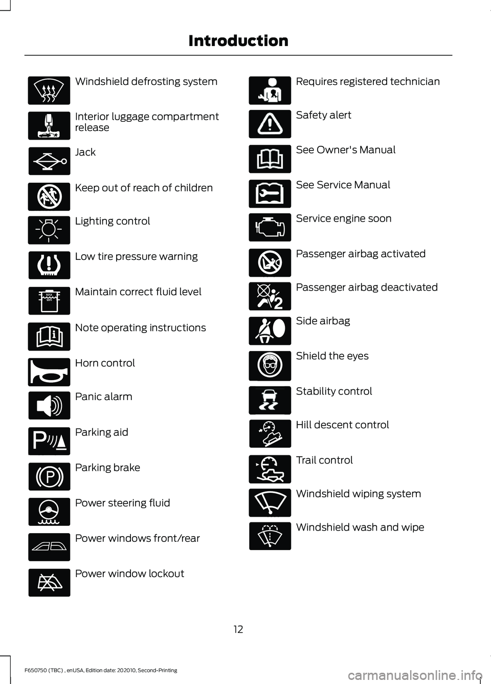
Windshield defrosting system
Interior luggage compartment
release
Jack
Keep out of reach of children
Lighting control
Low tire pressure warning
Maintain correct fluid level
Note operating instructions
Horn control
Panic alarm
Parking aid
Parking brake
Power steering fluid
Power windows front/rear
Power window lockout Requires registered technician
Safety alert
See Owner's Manual
See Service Manual
Service engine soon
Passenger airbag activated
Passenger airbag deactivated
Side airbag
Shield the eyes
Stability control
Hill descent control
Trail control
Windshield wiping system
Windshield wash and wipe
12
F650750 (TBC) , enUSA, Edition date: 202010, Second-Printing Introduction E161353 E270945 E139213 E231159 E231158 E270849 E270850 E167012 E138639 E163957 E272858 E270969
Page 16 of 390
DATA RECORDING
WARNING: Do not connect
wireless plug-in devices to the data link
connector. Unauthorized third parties
could gain access to vehicle data and
impair the performance of safety related
systems. Only allow repair facilities that
follow our service and repair instructions
to connect their equipment to the data
link connector.
We respect your privacy and are
committed to protecting it. The
information contained in this publication
was correct at the time of going to print,
but as technology rapidly changes, we
recommend that you visit the regional Ford
website for the latest information.
Your vehicle has electronic control units
that have data recording functionality and
the ability to permanently or temporarily
store data. This data could include
information on the condition and status of
your vehicle, vehicle maintenance
requirements, events and malfunctions.
The types of data that can be recorded are
described in this section. Some of the data
recorded is stored in event logs or error
logs.
Note: Error logs are reset following a service
or repair.
Note: We may provide information in
response to requests from law enforcement,
other government authorities and third
parties acting with lawful authority or
through a legal process. Such information
could be used by them in legal proceedings. Data recorded includes, for example:
•
Operating states of system
components, for example, fuel level,
tire pressure and battery charge level.
• Vehicle and component status, for
example, wheel speed, deceleration,
lateral acceleration and seatbelt
status.
• Events or errors in essential systems,
for example, headlamps and brakes.
• System responses to driving situations,
for example, airbag deployment and
stability control.
• Environmental conditions, for example,
temperature.
Some of this data, when used in
combination with other information, for
example, an accident report, damage to a
vehicle or eyewitness statements, could
be associated with a specific person.
Service Data
Service data recorders in your vehicle are
capable of collecting and storing
diagnostic information about your vehicle.
This potentially includes information about
the performance or status of various
systems and modules in the vehicle, such
as engine, throttle, steering or brake
systems. In order to properly diagnose and
service your vehicle, Ford Motor Company
(Ford of Canada in Canada), and service
and repair facilities may access or share
among them vehicle diagnostic
information received through a direct
connection to your vehicle when
diagnosing or servicing your vehicle.
Additionally, Ford Motor Company (Ford
of Canada, in Canada) may, where
permitted by law, use vehicle diagnostic
information for vehicle improvement or
with other information we may have about
you, for example, your contact information,
to offer you products or services that may
interest you. Data may be provided to our
13
F650750 (TBC) , enUSA, Edition date: 202010, Second-Printing Introduction
Page 76 of 390
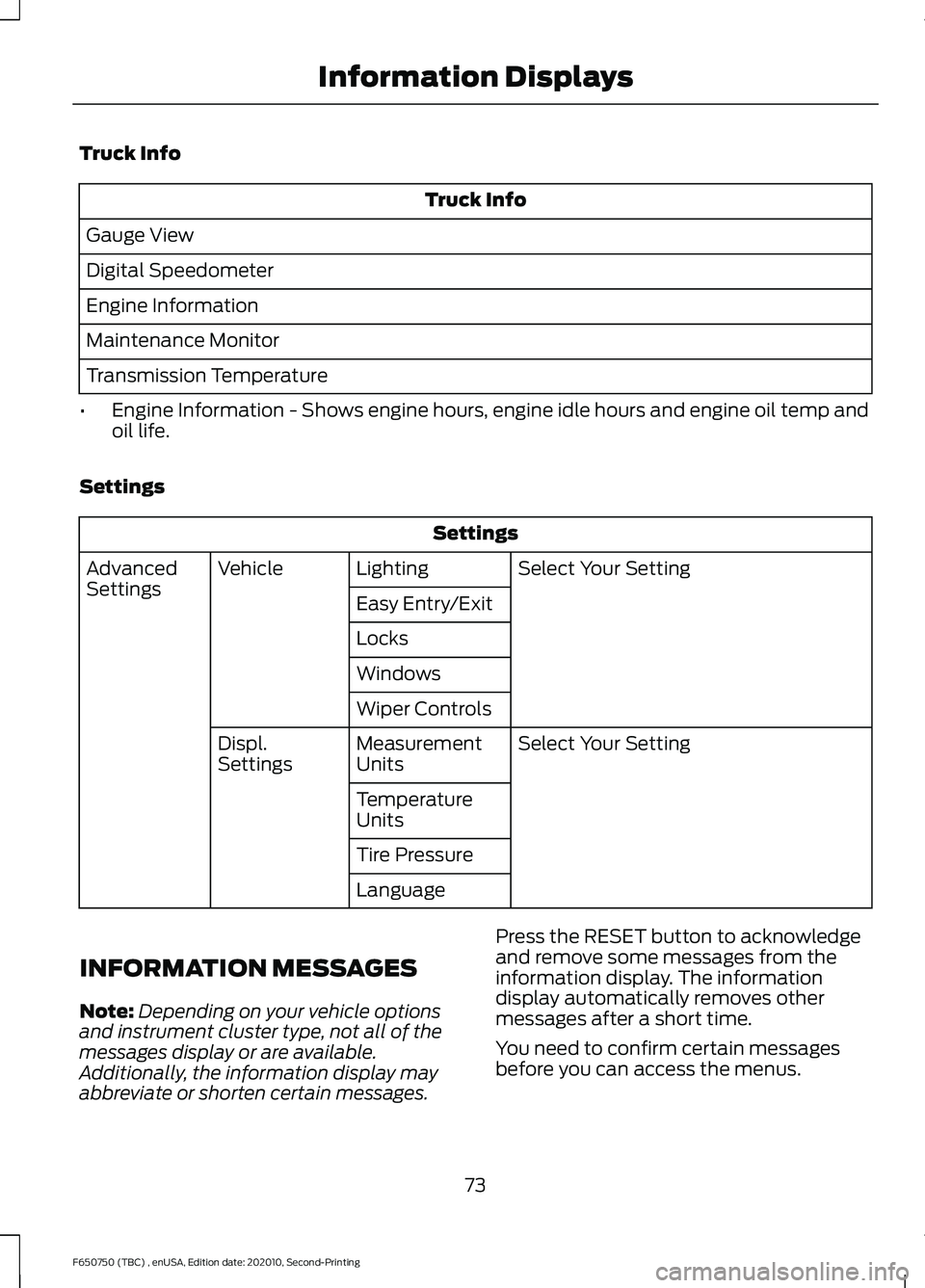
Truck Info
Truck Info
Gauge View
Digital Speedometer
Engine Information
Maintenance Monitor
Transmission Temperature
• Engine Information - Shows engine hours, engine idle hours and engine oil temp and
oil life.
Settings Settings
Select Your Setting
Lighting
Vehicle
Advanced
Settings
Easy Entry/Exit
Locks
Windows
Wiper Controls
Select Your Setting
Measurement
Units
Displ.
Settings
Temperature
Units
Tire Pressure
Language
INFORMATION MESSAGES
Note: Depending on your vehicle options
and instrument cluster type, not all of the
messages display or are available.
Additionally, the information display may
abbreviate or shorten certain messages. Press the RESET button to acknowledge
and remove some messages from the
information display. The information
display automatically removes other
messages after a short time.
You need to confirm certain messages
before you can access the menus.
73
F650750 (TBC) , enUSA, Edition date: 202010, Second-Printing Information Displays
Page 129 of 390
If you do not have a blown fuse and the
brake lamps are properly working, the
following procedure allows you to move
the gearshift lever from park (P):
1. Apply the parking brake. Switch the
ignition key to off, then remove the key.
2. Move the steering column to the full down and full rearward position,
toward the driver seat.
3. Remove the gearshift lever boot.
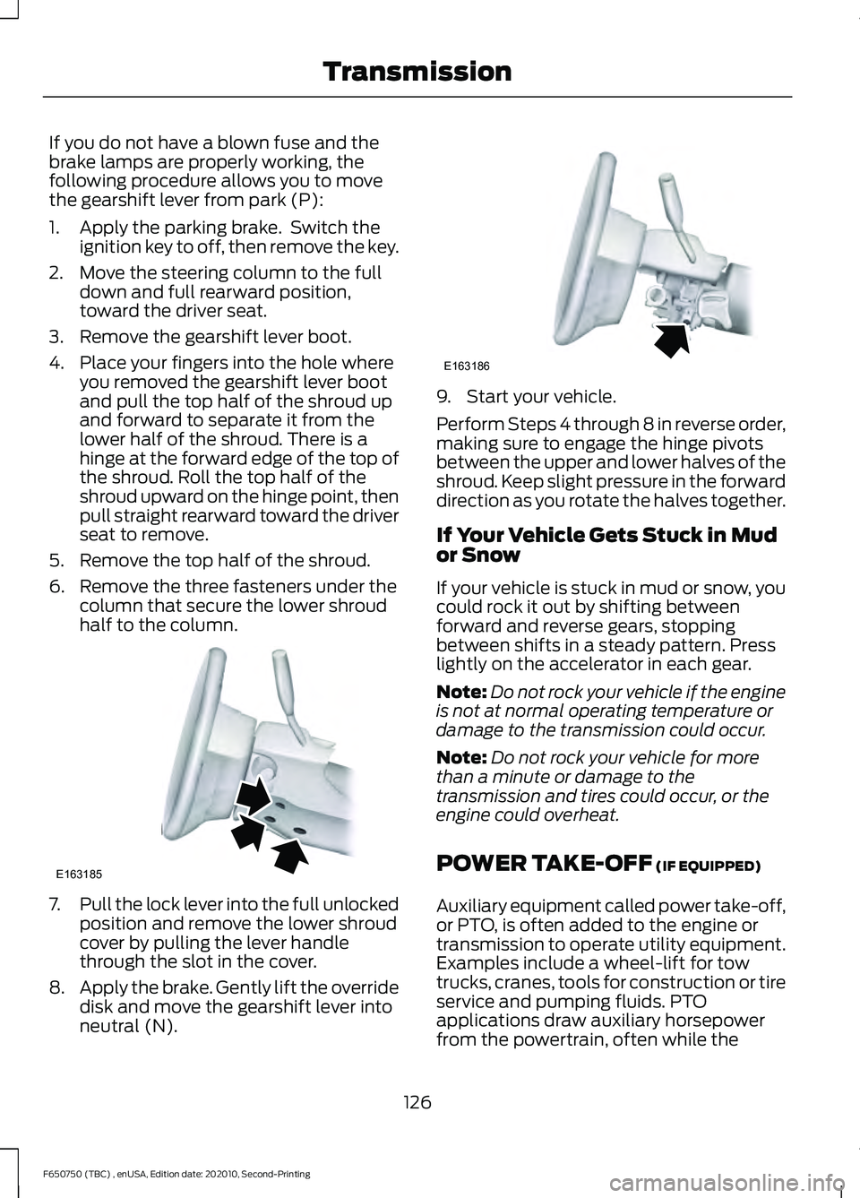
4. Place your fingers into the hole where you removed the gearshift lever boot
and pull the top half of the shroud up
and forward to separate it from the
lower half of the shroud. There is a
hinge at the forward edge of the top of
the shroud. Roll the top half of the
shroud upward on the hinge point, then
pull straight rearward toward the driver
seat to remove.
5. Remove the top half of the shroud.
6. Remove the three fasteners under the column that secure the lower shroud
half to the column. 7.
Pull the lock lever into the full unlocked
position and remove the lower shroud
cover by pulling the lever handle
through the slot in the cover.
8. Apply the brake. Gently lift the override
disk and move the gearshift lever into
neutral (N). 9. Start your vehicle.
Perform Steps 4 through 8 in reverse order,
making sure to engage the hinge pivots
between the upper and lower halves of the
shroud. Keep slight pressure in the forward
direction as you rotate the halves together.
If Your Vehicle Gets Stuck in Mud
or Snow
If your vehicle is stuck in mud or snow, you
could rock it out by shifting between
forward and reverse gears, stopping
between shifts in a steady pattern. Press
lightly on the accelerator in each gear.
Note:
Do not rock your vehicle if the engine
is not at normal operating temperature or
damage to the transmission could occur.
Note: Do not rock your vehicle for more
than a minute or damage to the
transmission and tires could occur, or the
engine could overheat.
POWER TAKE-OFF (IF EQUIPPED)
Auxiliary equipment called power take-off,
or PTO, is often added to the engine or
transmission to operate utility equipment.
Examples include a wheel-lift for tow
trucks, cranes, tools for construction or tire
service and pumping fluids. PTO
applications draw auxiliary horsepower
from the powertrain, often while the
126
F650750 (TBC) , enUSA, Edition date: 202010, Second-Printing TransmissionE163185 E163186
Page 131 of 390
GENERAL INFORMATION
WARNING: Exceeding these ratings
by overloading can cause component
failure resulting in property damage,
personal injury or death.
Fluid Temperature
If the operating temperature exceeds
250°F (121°C), the rate of axle lubrication
oxidation increases and shortens the life
of the lubricant and seals, requiring axle
lubrication changes to become more
frequent to preserve the axle. Do not
consistently run extreme pressure (EP)
lubricants above
250°F (121°C).
Axle Conversions WARNING:
When operating a
loaded vehicle, the driver must keep all
adjustable axles on the ground at all
times, supporting their share of the
vehicle ’s load. Failure to do so can
overload other axles, tires, wheels,
springs, steering components, brakes
and frames, resulting in early component
failure, loss of vehicle control, possible
property damage and personal injury.
We do not recommend, or approve,
performing axle conversions. However, we
understand that, on occasion, others install
aftermarket add-on axles on the truck
chassis that allow operator control for
weight transfer from other axles (such as
air lift axles). ELECTRONIC LOCKING
DIFFERENTIAL
(IF EQUIPPED)
Driver-Controlled Electronic
Locking Differential
Note: Never use the differential lock at
vehicle speeds above
25 mph (40 km/h).
Some drive axles have a driver-controlled
differential lock. The differential lock can
lock or unlock the differential when your
vehicle is moving or stopped. When you
require extra traction, the differential lock
provides full power to both wheels.
When you lock the differential, your
vehicle ’s turning radius increases
(under-steer).
Take care to avoid sudden accelerations
when both drive wheels are on a slippery
surface. WARNING:
Sudden acceleration
on slippery surfaces could cause the
wheels to spin, the vehicle to turn
sideways on a crowned road surface or
in a turn, possibly resulting in loss of
vehicle control and personal injury.
Activating the Electronic Locking
Differential
You can lock and unlock the differential
when your vehicle is moving at a constant
speed of less than 25 mph (40 km/h) and
while the wheels are not slipping. Do not
lock the differential when your vehicle is
traveling down steep grades and when
traction is minimal.
The differential lock and differential lock
light automatically disengage at speeds
above
25 mph (40 km/h). The differential
lock remains off until either you restart your
vehicle, or you turn the differential lock
switch off then back on.
128
F650750 (TBC) , enUSA, Edition date: 202010, Second-Printing Rear Axle
Page 172 of 390
AIR SUSPENSION (IF EQUIPPED)
Note: Do not operate your vehicle without
air in the suspension springs. Operating your
vehicle without air in the suspension springs
damages the suspension, degrades ride
performance and may cause property
damage.
The air suspension system automatically
adjusts to different loads to maintain a
constant frame height, allows for ease of
vehicle loading, provides improved vehicle
ride, and increased driver comfort.
Air Suspension Dump Button Note:
The suspension dumps air when the
ignition is in the accessory or on position,
but fills only when the ignition is in the on
position.
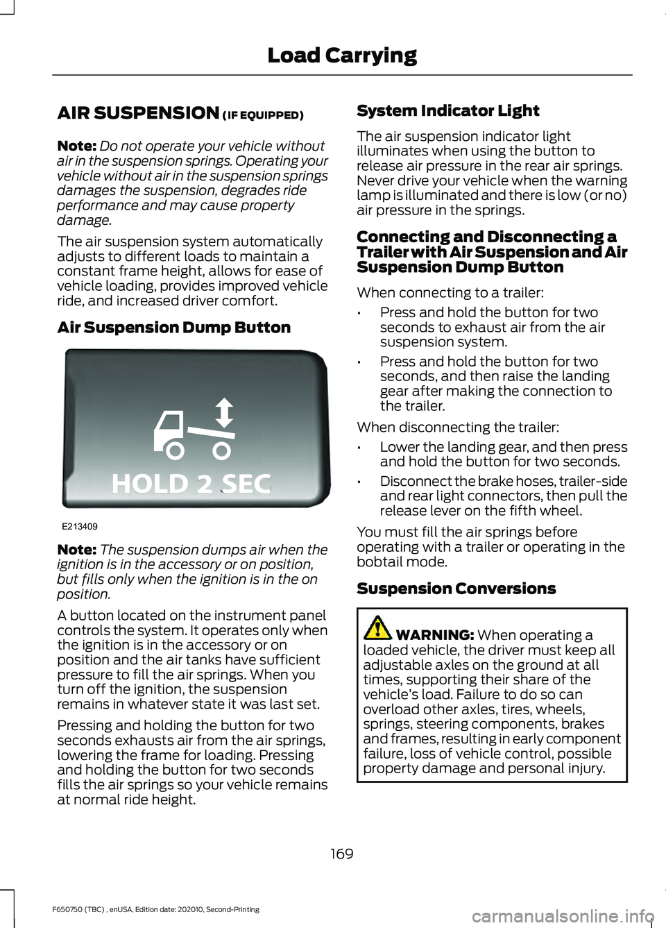
A button located on the instrument panel
controls the system. It operates only when
the ignition is in the accessory or on
position and the air tanks have sufficient
pressure to fill the air springs. When you
turn off the ignition, the suspension
remains in whatever state it was last set.
Pressing and holding the button for two
seconds exhausts air from the air springs,
lowering the frame for loading. Pressing
and holding the button for two seconds
fills the air springs so your vehicle remains
at normal ride height. System Indicator Light
The air suspension indicator light
illuminates when using the button to
release air pressure in the rear air springs.
Never drive your vehicle when the warning
lamp is illuminated and there is low (or no)
air pressure in the springs.
Connecting and Disconnecting a
Trailer with Air Suspension and Air
Suspension Dump Button
When connecting to a trailer:
•
Press and hold the button for two
seconds to exhaust air from the air
suspension system.
• Press and hold the button for two
seconds, and then raise the landing
gear after making the connection to
the trailer.
When disconnecting the trailer:
• Lower the landing gear, and then press
and hold the button for two seconds.
• Disconnect the brake hoses, trailer-side
and rear light connectors, then pull the
release lever on the fifth wheel.
You must fill the air springs before
operating with a trailer or operating in the
bobtail mode.
Suspension Conversions WARNING:
When operating a
loaded vehicle, the driver must keep all
adjustable axles on the ground at all
times, supporting their share of the
vehicle ’s load. Failure to do so can
overload other axles, tires, wheels,
springs, steering components, brakes
and frames, resulting in early component
failure, loss of vehicle control, possible
property damage and personal injury.
169
F650750 (TBC) , enUSA, Edition date: 202010, Second-Printing Load CarryingE213409
Page 180 of 390
ECONOMICAL DRIVING
Your fuel economy is affected by several
things, such as how you drive, the
conditions you drive under, and how you
maintain your vehicle.
You may improve your fuel economy by
keeping these things in mind:
•
Accelerate and slow down in a smooth,
moderate fashion.
• Drive at steady speeds without
stopping.
• Anticipate stops; slowing down may
eliminate the need to stop.
• Close the windows for high-speed
driving.
• Drive at reasonable speeds. Traveling
at 55 mph (90 km/h) uses 15% less
fuel than traveling at 65 mph
(105 km/h).
• Keep the tires properly inflated and use
only the recommended size.
• Use the recommended engine oil.
• Perform all regularly scheduled
maintenance.
Avoid these actions; they reduce your fuel
economy:
• Sudden accelerations or hard
accelerations.
• Warm up your vehicle on cold
mornings.
• Use the air conditioner.
• Use the speed control in hilly terrain.
• Rest your foot on the brake pedal while
driving.
• Carry unnecessary weight.
Approximately 1 mpg [0.4 km/L] is lost
for every
400 lb (180 kg) of weight
carried.
• Driving with the wheels out of
alignment. Conditions
•
Adding certain accessories to your
vehicle may reduce fuel economy. For
example bug deflectors, rollbars, light
bars, running boards, ski racks or
luggage racks.
• Using fuel blended with alcohol may
lower fuel economy.
• Fuel economy may decrease with lower
temperatures during the first
5–10 mi
(12 –16 km) of driving.
• Driving on flat terrain offers improved
fuel economy as compared to driving
on hilly terrain.
• Transmissions give their best fuel
economy when operated in the top
cruise gear and with steady pressure
on the gas pedal.
COLD WEATHER
PRECAUTIONS
Note: Idling in cold weather does not heat
the engine to its normal operating
temperature. Long periods of idling,
especially in cold weather, can cause a
buildup of deposits which can cause engine
damage.
Changing to a lighter grade engine oil also
makes starting easier under these
conditions. Refer to Engine oil
specifications. See
Capacities and
Specifications (page 288).
Diesel fuel is adjusted seasonally for cold
temperatures. Diesel fuel which has not
been properly formulated for the ambient
conditions may gel which can clog the fuel
filters. One indication that the fuel filter(s)
may be clogged is if the engine starts, stalls
after a short time, and then does not
restart. If you have been using biodiesel,
you may need to use a fuel with lower
biodiesel content, try another brand, or
discontinue using biodiesel. Do not use
177
F650750 (TBC) , enUSA, Edition date: 202010, Second-Printing Driving Hints
Page 206 of 390
VEHICLE INSPECTION
INFORMATION
To make sure your vehicle is ready to
operate, conduct a pre-trip inspection at
the beginning of each work period. Follow
the steps listed in this section to verify a
proper vehicle inspection procedure.
WARNING: Exercise great caution
when working on a vehicle equipped with
an automatic fan clutch. The fan starts
in motion only after the engine coolant
reaches a predetermined temperature
or the refrigerant pressure (if equipped
with air conditioning) reaches a
predetermined setting. The fan starts at
this point with no advance warning.
Never reach near, or permit objects to
protrude into, the fan blade radius while
the engine is running as this could result
in vehicle damage, personal injury or
death. WARNING:
Do not operate the
vehicle if any suspension conditions
listed in the following charts are evident.
Loss of steering or suspension could
result in property damage, personal injury
or death. WARNING:
If a wheel must be
changed, obtain expert tire service help.
Mounting and un-mounting of tires
should only be performed by a qualified
technician using necessary safety
procedures and equipment, otherwise
the result could be property damage,
personal injury or death.
Note: Always make sure you apply the
parking brake before starting the engine. Engine compartment (with engine off)
Use the dipstick to verify the oil level is in the proper operating
range. See
Engine Oil Dipstick (page 217).
Engine oil
Look through the plastic reservoir and verify the coolant level
is within the proper operating range. Do not remove the
pressure cap until the coolant has cooled. See
Engine
Coolant Check (page 226).
Engine coolant
Verify that the fluid level is in the proper operating range. See
Power Steering Fluid Check
(page 238).
Power steering fluid
Remove the master cylinder caps and inspect the fluid level.
See
Brake Fluid Check (page 237).
Brake fluid
203
F650750 (TBC) , enUSA, Edition date: 202010, Second-Printing Vehicle Inspection Guide
Page 236 of 390
3. Refill with prediluted coolant as soon
as possible.
Water alone, without prediluted coolant,
can cause engine damage from corrosion,
overheating or freezing.
Do not use the following as a coolant
substitute:
• Alcohol.
• Methanol.
• Brine.
• Any coolant mixed with alcohol or
methanol antifreeze.
Alcohol and other liquids can cause engine
damage from overheating or freezing.
Do not add extra inhibitors or non-specified
additives to the coolant. These can be
harmful and compromise the corrosion
protection of the coolant.
Engine and Secondary Cooling
System Refill Procedure
The following procedure should be used
when refilling the engine or secondary
cooling systems after it has been drained
or become extremely low:
1. Before you remove the cap, turn the engine off and let it cool.
2. When the engine is cool, wrap a thick cloth around the cap. Slowly turn cap
counterclockwise until pressure begins
to release.
3. Step back when the pressure releases.
4. When you are sure that all the pressure
has been released, use the cloth to turn
the cap counterclockwise and then
remove it.
5. Slowly add prediluted engine coolant to the coolant reservoir until the
coolant level is within the minimum
and maximum range as listed on the
reservoir.
6. Reinstall the pressure relief cap. 7. Start and run the engine at 2000 rpm
for 2 minutes.
8. Shut engine off, and remove the pressure relief cap as previously
outlined.
9. If required, add prediluted engine coolant to the coolant reservoir until
the coolant level is within the minimum
and maximum range as listed on the
reservoir.
10. Engine cooling system: Repeat steps
5 through 9 until the coolant level has
stabilized (is no longer dropping after
each step) and the upper radiator
hose at the radiator is warm to the
touch (indicating that the engine
thermostat is open and coolant is
flowing through the radiator).
11. Check the secondary cooling system.
Repeat steps 1 through 10 until the
coolant level has stabilized (is no
longer dropping after each step) and
the lower passenger side of the
secondary radiator is warm to the
touch (indicating secondary
thermostat is open and coolant is
flowing through the entire system).
12. Check the coolant level in both systems before you drive your vehicle
the next few times.
13. If necessary, add prediluted engine coolant to the coolant reservoirs until
the coolant level is within the
minimum and maximum range as
listed on the reservoir. After any
coolant has been added, check the
coolant concentration.
Recycled Coolant
We do not recommend the use of recycled
coolant as an approved recycling process
is not yet available.
233
F650750 (TBC) , enUSA, Edition date: 202010, Second-Printing Maintenance
Page 254 of 390
inspection and keep to instructions
provided by the service manual.
Hydraulic brake systems are
power-assisted. There is a great
reduction in braking capabilities
without engine assist.
• Proper fluid level. The level should be
at the bottom edge of the ring on each
reservoir fill port. Do not fill the master
cylinder to the top of the reservoir. If
fluid level requires attention to
maintain a proper master cylinder level,
this is an indication of either severe
operation (pad wear) or fluid leakage.
A more frequent and thorough brake
inspection is required.
• Brake lines, hoses and fittings. Repair
or replace brake line tubes, hoses or
fittings as required. Inspect these
components every 4,000 mi
(6,000 km) for the following.
• Lines for kinks, dents, corrosion or
rupture.
• Hoses for abrasions, kinks, soft
spots or rupture, collapse, cracks,
twists or loose frame supports.
When replacing a hose, be sure
there is adequate clearance to the
hose to avoid an abrasion to the
new hose.
• All connections for leaks.
Driveline Parking Brake WARNING: Use wheel chocks and
exercise caution when inspecting under
the vehicle. A vehicle roll-away could
result in property damage, personal injury
or death.
A qualified technician should adjust the
parking brake and keep to the instructions
in the service manual. AXLE INSPECTION
Front Axle
Maintaining the front axle alignment to
specifications is very important. A qualified
technician should check and maintain the
alignment.
Regular inspections should include:
•
Toe-in inspection and adjustment (if
necessary), particularly with radial
tires.
• Checking for proper tightness of axle
mounting U-bolt nuts, attaching or
mounting bolts and nuts.
• Checking the axle for damage, binding,
worn parts and adequate lubrication.
• Checking the kingpins for excessive
wear. Also, perform this check during
other scheduled maintenance, for
example as tire rotation or service,
wheel bearing service and alignment.
See the workshop manual for proper
procedures.
Toe-in
It is essential to maintain correct toe-in
and tire pressure for optimum tire wear.
Inspecting steer axle tires in the first
3,000– 10,000 mi (5,000– 16,000 km)
generally shows if tires are wearing
normally.
Rapid outside shoulder wear on both tires
indicates too much toe-in.
Rapid inside shoulder wear on both tires
indicates too much toe-out.
In P&D-type service, there can be a
left-to-right steer tire tread life differential
up to 40% depending on routes and other
variables.
251
F650750 (TBC) , enUSA, Edition date: 202010, Second-Printing Maintenance