headlamp FORD F650/750 2024 User Guide
[x] Cancel search | Manufacturer: FORD, Model Year: 2024, Model line: F650/750, Model: FORD F650/750 2024Pages: 386, PDF Size: 8.7 MB
Page 74 of 386
WARNING: Do not use startingfluid, for example ether, in the air intakesystem. Such fluid could causeimmediate explosive damage to theengine and possible personal injury.
Water in Fuel (If Equipped)
Illuminates when the fuelfilter/water separator has asignificant quantity of water init.
If the light illuminates when the engine isrunning, stop the vehicle as soon as safelypossible, shut off the engine, then drain thefuel filter/water separator.
Allowing water to stay in the system couldresult in extensive damage to, or failure of,the fuel injection system.
WARNING: Do not drain thewater-in-fuel separator while the engineis running. Failure to follow this warningmay result in fire, serious injury, death orproperty damage.
AUDIBLE WARNINGS AND
INDICATORS
Headlamps On Warning Chime
Sounds when you remove the key from theignition and open the driver's door and youhave left the headlamps or parking lampson.
Key in Ignition Warning Chime
Sounds when you open the driver's doorand you have left the key in the ignition.
Parking Brake On Warning Chime
Sounds when you have left the parkingbrake on and drive your vehicle. If thewarning chime remains on after you havereleased the parking brake, have thesystem checked by your authorized dealerimmediately.
70
2024 F-650/750 (TBC) , enUSA, Edition date: 202210, First-PrintingInstrument Cluster
Page 106 of 386
Note:When you switch the ignition off andleave your vehicle, do not leave your key inthe ignition. This could cause your vehiclebattery to lose charge.
I (accessory) - Allows the electricalaccessories, such as the radio, to operatewhile the engine is not running.
Note:Do not leave the ignition key in thisposition for too long. This could cause yourvehicle battery to lose charge.
II (on) - All electrical circuits areoperational and the warning lamps andindicators illuminate.
III (start) - Cranks the engine.
STARTING A GASOLINE
ENGINE
When you start the engine, the idle speedincreases helping to warm up the engine.If the engine idle speed does not slowdown, have your vehicle checked as soonas possible.
Before starting the engine check thefollowing:
•Make sure all occupants fasten theirseatbelts.
•Make sure the headlamps andelectrical accessories are off.
•Make sure the parking brake is on.
•Make sure the transmission is in park(P) or neutral (N).
•Turn the ignition key to the on position.
Note:Do not press the accelerator pedal.
1.Fully press the brake pedal.
2.Turn the key to the start position tostart the engine. Release the key whenthe engine starts.
Note:The engine may continue crankingfor up to 15 seconds or until it starts.
Note:If you cannot start the engine on thefirst try, wait for a short period and try again.
Failure to Start
If you cannot start the engine after threeattempts, wait 10 seconds and follow thisprocedure:
1.Fully press the brake pedal.
2.Shift into park (P).
3.Fully press and hold the acceleratorpedal.
4.Attempt to start your vehicle and waituntil the engine stops cranking.
5.Release the accelerator pedal.
6.Start the engine.
Stopping the Engine When YourVehicle is Stationary
1.Shift into park (P) or neutral (N).
2.Turn the key to the off position.
3.Apply the parking brake.
Stopping the Engine When YourVehicle is Moving
WARNING: Switching off theengine when your vehicle is still movingresults in a significant decrease inbraking assistance. Higher effort isrequired to apply the brakes and to stopyour vehicle. A significant decrease insteering assistance could also occur. Thesteering does not lock, but higher effortcould be required to steer your vehicle.When you switch the ignition off, someelectrical circuits, for example airbags,also turn off. If you unintentionally switchthe ignition off, shift into neutral (N) andrestart the engine.
1.Switch the ignition off to stop theengine.
102
2024 F-650/750 (TBC) , enUSA, Edition date: 202210, First-PrintingStarting and Stopping the Engine
Page 107 of 386
2.Put the transmission into neutral (N)and use the brakes to bring your vehicleto a safe stop.
3.When your vehicle has stopped, shiftinto park (P).
4.Apply the parking brake.
Guarding Against Exhaust Fumes
WARNING: Exhaust leaks mayresult in entry of harmful and potentiallylethal fumes into the passengercompartment. If you smell exhaustfumes inside your vehicle, have yourvehicle inspected immediately. Do notdrive if you smell exhaust fumes.
Important Ventilating Information
If you stop your vehicle and leave theengine idling for long periods of time, werecommend you either open the windowsat least 1 in (3 cm) or set the climatecontrol to outside air.
STARTING A DIESEL ENGINE
Read all starting instructions carefullybefore you start your vehicle.
The 6.7L diesel engine incorporates a delaybetween a crank command and starterengagement to crank the engine. Thisdelay ensures robust starting performancein all environmental conditions includingextreme cold. The crank command isinitiated by the operator by turning theignition key. The delay varies with enginecoolant temperature. There is no delay forhot coolant temperature. The delayincreases at colder coolant temperatures.Maximum delay of 2.5 seconds isexperienced below -13.0°F (-25°C).
Diesel Engine Fast Start Glow PlugSystem
The diesel engine glow system consists of:
•Eight glow plugs, one per cylinder.
•Glow plug control module.
•Engine coolant temperature sensor.
•Barometric pressure sensor.
•Environmental temperature sensor.
The powertrain and glow plug controlmodules electronically control the glowplug system. After you switch the ignitionon, the glow plug control moduleimmediately energizes the glow plugs. Theglow plug control module, using the enginecoolant temperature, barometric pressuresensor and environmental temperaturesensor, determines how long the glowplugs stay energized. The required time forthe glow plugs to be energized decreasesas the coolant temperature, barometricpressure and environmental temperatureincrease.
Before starting the engine, check thefollowing:
•Make sure all occupants fasten theirseatbelt.
•Make sure the headlamps andelectrical accessories are off.
•Make sure the parking brake is on.
•Make sure the transmission is in park(P) or neutral (N).
•Turn the ignition key to the on position.
Note:Do not press the accelerator duringstarting.
1.Fully press the brake pedal.
2.Turn the key to the start position tostart the engine. Release the key whenthe engine starts.
103
2024 F-650/750 (TBC) , enUSA, Edition date: 202210, First-PrintingStarting and Stopping the Engine
Page 172 of 386
When you switch the lane keeping systemon and the camera detects a drift out ofthe travel lane, the system alerts the driverby playing a chime.
Switching the System On and Off
Note:The system stores the on or offsetting until you manually change it.
Press the button to switch thesystem on or off. The button isabove the audio unit or on thecenter console.
System Settings
Adjust the system sensitivity and intensitythrough the display screen. The systemremembers the last selection. You do notneed to readjust the setting each time youswitch on your vehicle.
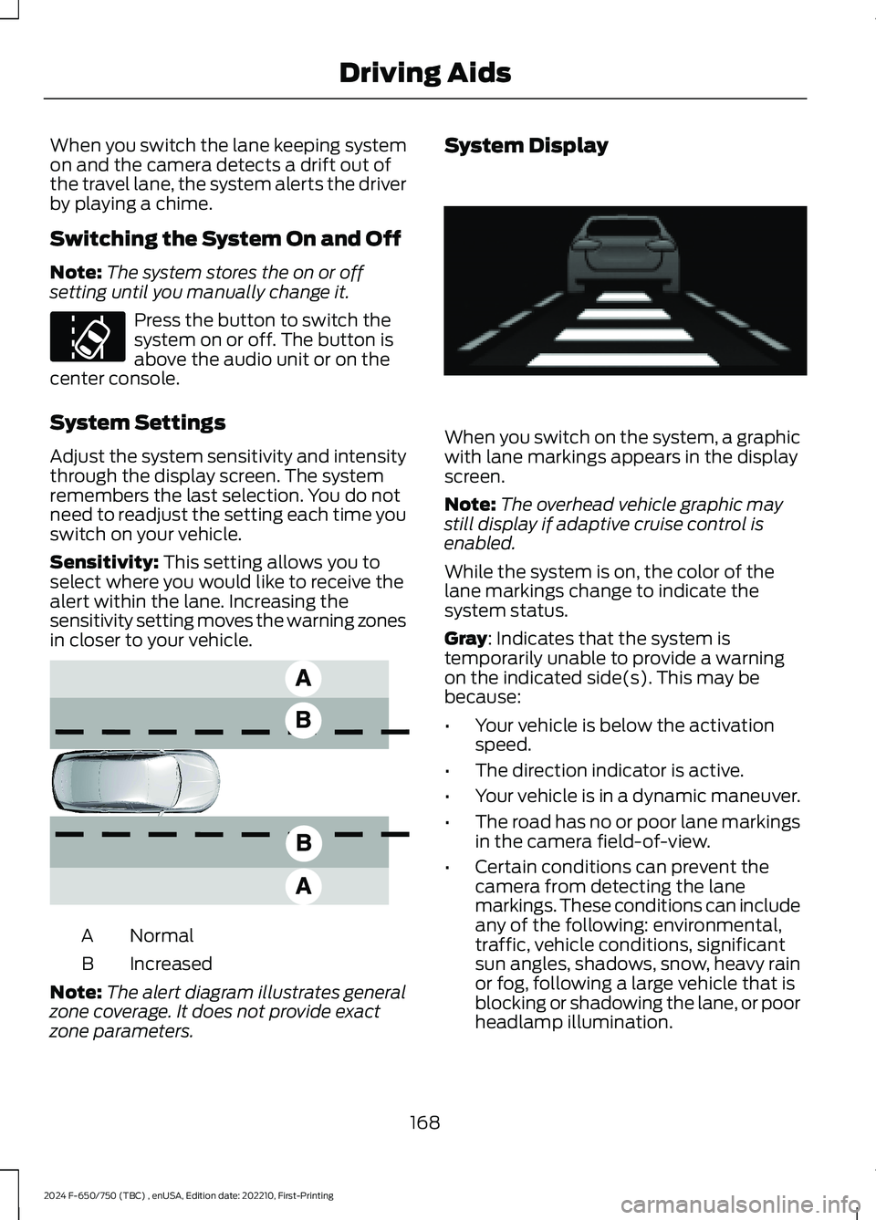
Sensitivity: This setting allows you toselect where you would like to receive thealert within the lane. Increasing thesensitivity setting moves the warning zonesin closer to your vehicle.
NormalA
IncreasedB
Note:The alert diagram illustrates generalzone coverage. It does not provide exactzone parameters.
System Display
When you switch on the system, a graphicwith lane markings appears in the displayscreen.
Note:The overhead vehicle graphic maystill display if adaptive cruise control isenabled.
While the system is on, the color of thelane markings change to indicate thesystem status.
Gray: Indicates that the system istemporarily unable to provide a warningon the indicated side(s). This may bebecause:
•Your vehicle is below the activationspeed.
•The direction indicator is active.
•Your vehicle is in a dynamic maneuver.
•The road has no or poor lane markingsin the camera field-of-view.
•Certain conditions can prevent thecamera from detecting the lanemarkings. These conditions can includeany of the following: environmental,traffic, vehicle conditions, significantsun angles, shadows, snow, heavy rainor fog, following a large vehicle that isblocking or shadowing the lane, or poorheadlamp illumination.
168
2024 F-650/750 (TBC) , enUSA, Edition date: 202210, First-PrintingDriving AidsE173233 E165517 E233874
Page 252 of 386
the driver that battery protection actionsare active. These messages are only fornotification that an action is taking place,and not intended to indicate an electricalproblem or that the battery requiresreplacement.
Electrical accessory installation
To ensure proper operation of the BMS,any electrical devices that are added tothe vehicle should not have their groundconnection made directly at the negativebattery post. A connection at the negativebattery post can cause inaccuratemeasurements of the battery conditionand potential incorrect system operation.
Note:Electrical or electronic accessoriesadded to the vehicle by the dealer or theowner may adversely affect batteryperformance and durability, and may alsoaffect the performance of other electricalsystems in the vehicle.
When a battery replacement is required,the battery should only be replaced witha Ford recommended replacement batterywhich matches the electrical requirementsof the vehicle. After battery replacement,or in some cases after charging the batterywith the external charger, the BMS requireseight hours of vehicle sleep time (key offwith doors closed) to relearn the newbattery state of charge. Prior to relearningthe state of charge, the BMS may disableelectrical features (to protect the battery)earlier than normal.
ADJUSTING THE HEADLAMPS
Vertical Aim Adjustment
The headlamps on your vehicle areproperly aimed at the assembly plant. Ifyour vehicle has been in an accident, thealignment of your headlamps should bechecked by your authorized dealer.
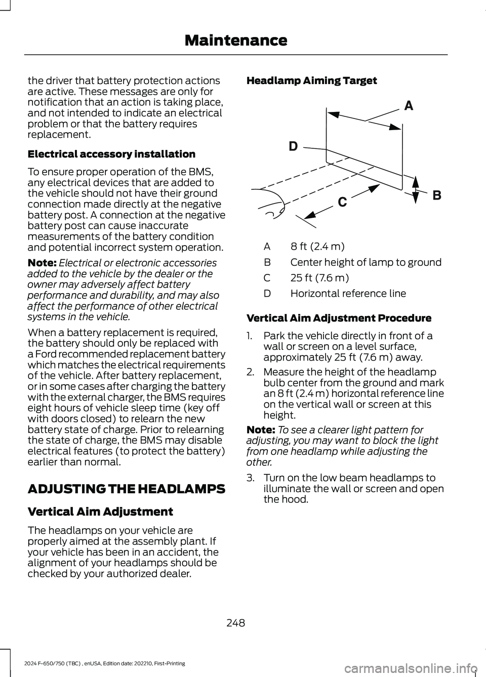
Headlamp Aiming Target
8 ft (2.4 m)A
Center height of lamp to groundB
25 ft (7.6 m)C
Horizontal reference lineD
Vertical Aim Adjustment Procedure
1.Park the vehicle directly in front of awall or screen on a level surface,approximately 25 ft (7.6 m) away.
2.Measure the height of the headlampbulb center from the ground and markan 8 ft (2.4 m) horizontal reference lineon the vertical wall or screen at thisheight.
Note:To see a clearer light pattern foradjusting, you may want to block the lightfrom one headlamp while adjusting theother.
3.Turn on the low beam headlamps toilluminate the wall or screen and openthe hood.
248
2024 F-650/750 (TBC) , enUSA, Edition date: 202210, First-PrintingMaintenanceE142592
Page 253 of 386
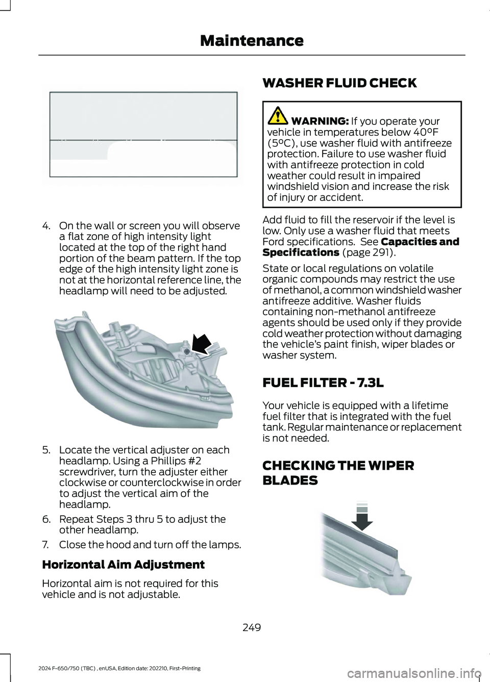
4.On the wall or screen you will observea flat zone of high intensity lightlocated at the top of the right handportion of the beam pattern. If the topedge of the high intensity light zone isnot at the horizontal reference line, theheadlamp will need to be adjusted.
5.Locate the vertical adjuster on eachheadlamp. Using a Phillips #2screwdriver, turn the adjuster eitherclockwise or counterclockwise in orderto adjust the vertical aim of theheadlamp.
6.Repeat Steps 3 thru 5 to adjust theother headlamp.
7.Close the hood and turn off the lamps.
Horizontal Aim Adjustment
Horizontal aim is not required for thisvehicle and is not adjustable.
WASHER FLUID CHECK
WARNING: If you operate yourvehicle in temperatures below 40°F(5°C), use washer fluid with antifreezeprotection. Failure to use washer fluidwith antifreeze protection in coldweather could result in impairedwindshield vision and increase the riskof injury or accident.
Add fluid to fill the reservoir if the level islow. Only use a washer fluid that meetsFord specifications. See Capacities andSpecifications (page 291).
State or local regulations on volatileorganic compounds may restrict the useof methanol, a common windshield washerantifreeze additive. Washer fluidscontaining non-methanol antifreezeagents should be used only if they providecold weather protection without damagingthe vehicle’s paint finish, wiper blades orwasher system.
FUEL FILTER - 7.3L
Your vehicle is equipped with a lifetimefuel filter that is integrated with the fueltank. Regular maintenance or replacementis not needed.
CHECKING THE WIPER
BLADES
249
2024 F-650/750 (TBC) , enUSA, Edition date: 202210, First-PrintingMaintenanceE142465 E163806 E142463
Page 254 of 386
Run the tip of your fingers over the edge ofthe blade to check for roughness.
Clean the wiper blades with washer fluidor water applied with a soft sponge orcloth.
CHANGING THE WIPER
BLADES
You can manually move the wiper armswhen the ignition is off. This allows for easeof blade replacement and cleaning underthe blades.
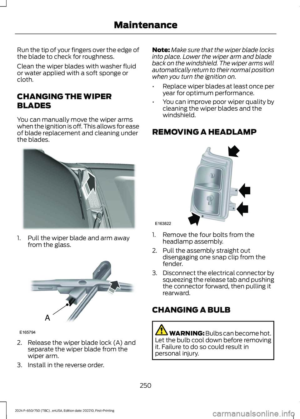
1.Pull the wiper blade and arm awayfrom the glass.
2.Release the wiper blade lock (A) andseparate the wiper blade from thewiper arm.
3.Install in the reverse order.
Note:Make sure that the wiper blade locksinto place. Lower the wiper arm and bladeback on the windshield. The wiper arms willautomatically return to their normal positionwhen you turn the ignition on.
•Replace wiper blades at least once peryear for optimum performance.
•You can improve poor wiper quality bycleaning the wiper blades and thewindshield.
REMOVING A HEADLAMP
1.Remove the four bolts from theheadlamp assembly.
2.Pull the assembly straight outdisengaging one snap clip from thefender.
3.Disconnect the electrical connector bysqueezing the release tab and pushingthe connector forward, then pulling itrearward.
CHANGING A BULB
WARNING: Bulbs can become hot.Let the bulb cool down before removingit. Failure to do so could result inpersonal injury.
250
2024 F-650/750 (TBC) , enUSA, Edition date: 202210, First-PrintingMaintenanceE165804 AE165794 E163822
Page 255 of 386
Headlamp bulbs must be marked with anauthorized D.O.T. marking for NorthAmerica to make sure they have the properlamp performance, light brightness, lightpattern and safe visibility.
Install in the reverse order unless otherwisestated.
Headlamp Bulbs
1.Switch all of the lamps and the ignitionoff.
2.Remove the headlamp. SeeRemoving a Headlamp (page 250).
3.Release the clip and remove the bulb.
Note:Do not touch the bulb glass.
Note:If the bulb is accidentally touched, itshould be cleaned with rubbing alcoholbefore being used.
Front Clearance and IdentificationLamp (If Equipped)
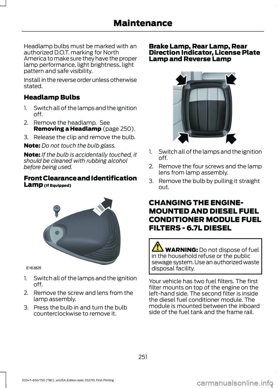
1.Switch all of the lamps and the ignitionoff.
2.Remove the screw and lens from thelamp assembly.
3.Press the bulb in and turn the bulbcounterclockwise to remove it.
Brake Lamp, Rear Lamp, RearDirection Indicator, License PlateLamp and Reverse Lamp
1.Switch all of the lamps and the ignitionoff.
2.Remove the four screws and the lamplens from lamp assembly.
3.Remove the bulb by pulling it straightout.
CHANGING THE ENGINE-
MOUNTED AND DIESEL FUEL
CONDITIONER MODULE FUEL
FILTERS - 6.7L DIESEL
WARNING: Do not dispose of fuelin the household refuse or the publicsewage system. Use an authorized wastedisposal facility.
Your vehicle has two fuel filters. The firstfilter mounts on top of the engine on theleft-hand side. The second filter is insidethe diesel fuel conditioner module. Themodule is mounted between the inboardside of the fuel tank and the frame rail.
251
2024 F-650/750 (TBC) , enUSA, Edition date: 202210, First-PrintingMaintenanceE163825 E163828
Page 300 of 386
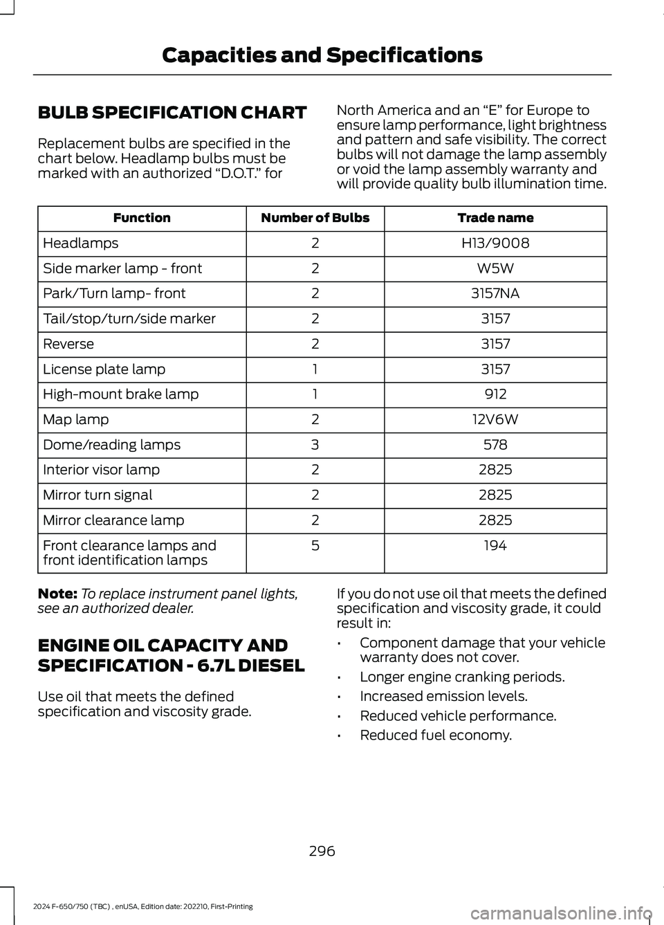
BULB SPECIFICATION CHART
Replacement bulbs are specified in thechart below. Headlamp bulbs must bemarked with an authorized “D.O.T.” for
North America and an “E” for Europe toensure lamp performance, light brightnessand pattern and safe visibility. The correctbulbs will not damage the lamp assemblyor void the lamp assembly warranty andwill provide quality bulb illumination time.
Trade nameNumber of BulbsFunction
H13/90082Headlamps
W5W2Side marker lamp - front
3157NA2Park/Turn lamp- front
31572Tail/stop/turn/side marker
31572Reverse
31571License plate lamp
9121High-mount brake lamp
12V6W2Map lamp
5783Dome/reading lamps
28252Interior visor lamp
28252Mirror turn signal
28252Mirror clearance lamp
1945Front clearance lamps andfront identification lamps
Note:To replace instrument panel lights,see an authorized dealer.
ENGINE OIL CAPACITY AND
SPECIFICATION - 6.7L DIESEL
Use oil that meets the definedspecification and viscosity grade.
If you do not use oil that meets the definedspecification and viscosity grade, it couldresult in:
•Component damage that your vehiclewarranty does not cover.
•Longer engine cranking periods.
•Increased emission levels.
•Reduced vehicle performance.
•Reduced fuel economy.
296
2024 F-650/750 (TBC) , enUSA, Edition date: 202210, First-PrintingCapacities and Specifications
Page 381 of 386
2
2-Speed Rear Axle.......................................136
A
A/CSee: Climate Control..........................................86About This Manual...........................................7ABSSee: Brakes...........................................................139ABS driving hintsSee: Hints on Driving With Anti-LockBrakes................................................................140Accessories.....................................................321AccessoriesSee: Replacement PartsRecommendation............................................15ACCSee: Using Adaptive Cruise Control.............159Adjusting the Headlamps........................248Adjusting the Steering Wheel....................52Air Brakes.........................................................144Air ConditioningSee: Climate Control..........................................86Air Conditioning System Capacity andSpecification - 6.7L Diesel....................305Air Conditioning System Capacity andSpecification - 7.3L..................................306Air FilterSee: Changing the Engine Air Filter - 6.7LDiesel.................................................................230See: Changing the Engine Air Filter -7.3L......................................................................232Air Induction System Inspection............255Air Suspension...............................................179Appendices.....................................................351At a Glance.......................................................24Audible Warnings and Indicators.............70Audio Input Jack............................................319Audio System.................................................315General Information..........................................315Audio Unit........................................................315Autolamps........................................................56Automatic Crash Shutoff..........................195Automatic Crash ShutoffPrecautions......................................................195Re-Enabling Your Vehicle................................195
What Is Automatic Crash Shutoff................195Automatic High Beam Control..................57Automatic Transmission...........................130Automatic Transmission Fluid Capacityand Specification - Diesel.....................307Automatic Transmission Fluid Capacityand Specification - Gasoline...............308Automatic Transmission FluidCheck.............................................................243Auxiliary Power Points.................................96Auxiliary Switches........................................321Axle Inspection.............................................259
B
BatterySee: Changing the 12V Battery.....................246Bonnet LockSee: Opening and Closing the Hood...........223Booster Seats..................................................33Brake Fluid Check........................................245Brake Fluid Specification.........................309Brakes...............................................................139General Information..........................................139Brake System Inspection..........................256Breaking-In.....................................................188Bulb Specification Chart..........................296
C
Canceling the Set Speed...........................159Capacities and Specifications.................291Car WashSee: Cleaning the Exterior..............................263Catalytic Converter.......................................118Changing a Bulb..........................................250Changing a Fuse.............................................211Changing a Road Wheel............................287Changing the 12V Battery.........................246Changing the Engine Air Filter - 6.7LDiesel.............................................................230Changing the Engine Air Filter -7.3L..................................................................232Changing the Engine-Mounted andDiesel Fuel Conditioner Module FuelFilters - 6.7L Diesel....................................251Changing the Engine Oil and OilFilter...............................................................228
377
2024 F-650/750 (TBC) , enUSA, Edition date: 202210, First-PrintingIndex