sensor FORD F650/750 2024 Owner's Manual
[x] Cancel search | Manufacturer: FORD, Model Year: 2024, Model line: F650/750, Model: FORD F650/750 2024Pages: 386, PDF Size: 8.7 MB
Page 177 of 386

Radar Troubleshooting
ActionCause
Clean the grille surface in front of the radaror remove the object causing the obstruc-tion.
The surface of the radar in the grille is dirtyor obstructed in some way.
Wait a short time. It may take severalminutes for the radar to detect that thereis no obstruction.
The surface of the radar in the grille is cleanbut the message remains in the displayscreen.
The Pre-Collision Assist system is tempor-arily disabled. Pre-Collision Assist automat-ically reactivates a short time after theweather conditions improve.
Heavy rain, spray, snow or fog is interferingwith the radar signals.
The Pre-Collision Assist system is tempor-arily disabled. Pre-Collision Assist automat-ically reactivates a short time after theweather conditions improve.
Swirling water or snow or ice on the surfaceof the road may interfere with the radarsignals.
Contact an authorized dealer to have theradar checked for proper coverage andoperation.
Radar is out of alignment due to a front endimpact.
Note:If something hits the front end of yourvehicle or damage occurs and your vehiclehas a radar sensor, the radar sensing zonemay change. This could cause missed orfalse vehicle detections. Contact anauthorized dealer to have the radar checkedfor proper coverage and operation.
PRE-COLLISION ASSIST -
VEHICLES WITH: HYDRAULIC
BRAKES
WARNING: You are responsible forcontrolling your vehicle at all times. Thesystem is designed to be an aid and doesnot relieve you of your responsibility todrive with due care and attention. Failureto follow this instruction could result inthe loss of control of your vehicle,personal injury or death.
173
2024 F-650/750 (TBC) , enUSA, Edition date: 202210, First-PrintingDriving Aids
Page 180 of 386
Note:Switch the system off if you install asnowplow or similar object in such a waythat it may block the radar sensor. Yourvehicle remembers the selected settingacross key cycles.
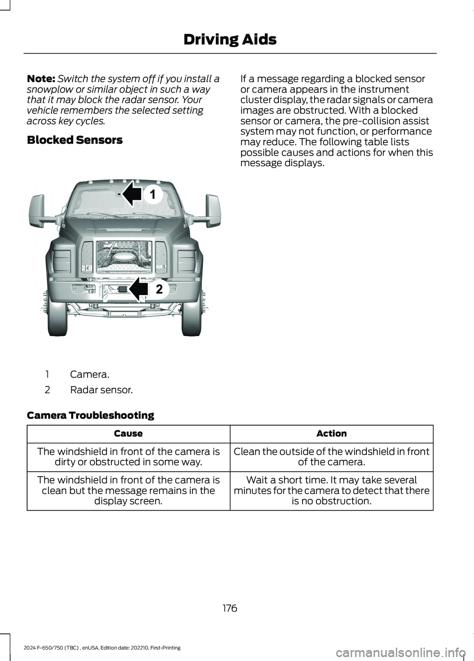
Blocked Sensors
Camera.1
Radar sensor.2
If a message regarding a blocked sensoror camera appears in the instrumentcluster display, the radar signals or cameraimages are obstructed. With a blockedsensor or camera, the pre-collision assistsystem may not function, or performancemay reduce. The following table listspossible causes and actions for when thismessage displays.
Camera Troubleshooting
ActionCause
Clean the outside of the windshield in frontof the camera.The windshield in front of the camera isdirty or obstructed in some way.
Wait a short time. It may take severalminutes for the camera to detect that thereis no obstruction.
The windshield in front of the camera isclean but the message remains in thedisplay screen.
176
2024 F-650/750 (TBC) , enUSA, Edition date: 202210, First-PrintingDriving AidsE311873
Page 181 of 386
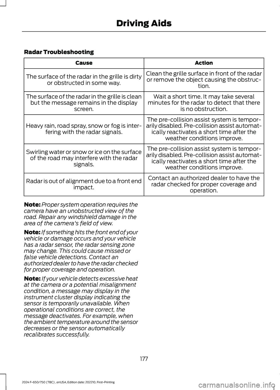
Radar Troubleshooting
ActionCause
Clean the grille surface in front of the radaror remove the object causing the obstruc-tion.
The surface of the radar in the grille is dirtyor obstructed in some way.
Wait a short time. It may take severalminutes for the radar to detect that thereis no obstruction.
The surface of the radar in the grille is cleanbut the message remains in the displayscreen.
The pre-collision assist system is tempor-arily disabled. Pre-collision assist automat-ically reactivates a short time after theweather conditions improve.
Heavy rain, road spray, snow or fog is inter-fering with the radar signals.
The pre-collision assist system is tempor-arily disabled. Pre-collision assist automat-ically reactivates a short time after theweather conditions improve.
Swirling water or snow or ice on the surfaceof the road may interfere with the radarsignals.
Contact an authorized dealer to have theradar checked for proper coverage andoperation.
Radar is out of alignment due to a front endimpact.
Note:Proper system operation requires thecamera have an unobstructed view of theroad. Repair any windshield damage in thearea of the camera's field of view.
Note:If something hits the front end of yourvehicle or damage occurs and your vehiclehas a radar sensor, the radar sensing zonemay change. This could cause missed orfalse vehicle detections. Contact anauthorized dealer to have the radar checkedfor proper coverage and operation.
Note:If your vehicle detects excessive heatat the camera or a potential misalignmentcondition, a message may display in theinstrument cluster display indicating thesensor is temporarily unavailable. Whenoperational conditions are correct, themessage deactivates. For example, whenthe ambient temperature around the sensordecreases or the sensor automaticallyrecalibrates successfully.
177
2024 F-650/750 (TBC) , enUSA, Edition date: 202210, First-PrintingDriving Aids
Page 208 of 386
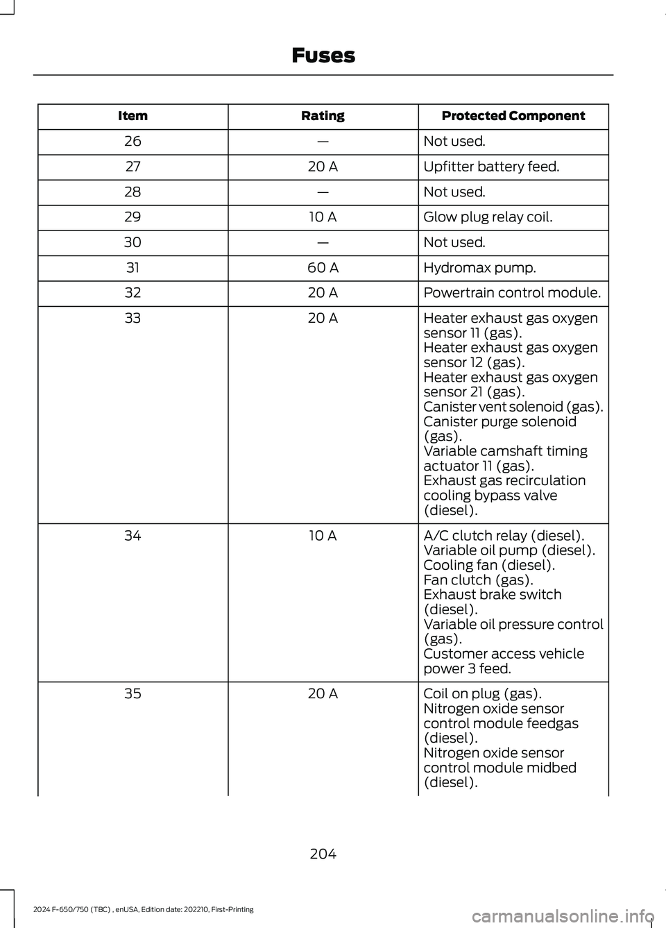
Protected ComponentRatingItem
Not used.—26
Upfitter battery feed.20 A27
Not used.—28
Glow plug relay coil.10 A29
Not used.—30
Hydromax pump.60 A31
Powertrain control module.20 A32
Heater exhaust gas oxygensensor 11 (gas).20 A33
Heater exhaust gas oxygensensor 12 (gas).Heater exhaust gas oxygensensor 21 (gas).Canister vent solenoid (gas).Canister purge solenoid(gas).Variable camshaft timingactuator 11 (gas).Exhaust gas recirculationcooling bypass valve(diesel).
A/C clutch relay (diesel).10 A34Variable oil pump (diesel).Cooling fan (diesel).Fan clutch (gas).Exhaust brake switch(diesel).Variable oil pressure control(gas).Customer access vehiclepower 3 feed.
Coil on plug (gas).20 A35Nitrogen oxide sensorcontrol module feedgas(diesel).Nitrogen oxide sensorcontrol module midbed(diesel).
204
2024 F-650/750 (TBC) , enUSA, Edition date: 202210, First-PrintingFuses
Page 209 of 386
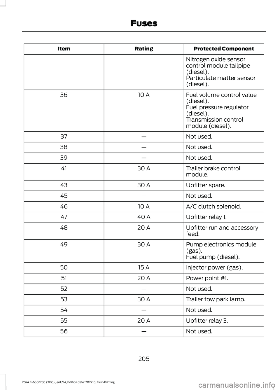
Protected ComponentRatingItem
Nitrogen oxide sensorcontrol module tailpipe(diesel).Particulate matter sensor(diesel).
Fuel volume control value(diesel).10 A36
Fuel pressure regulator(diesel).Transmission controlmodule (diesel).
Not used.—37
Not used.—38
Not used.—39
Trailer brake controlmodule.30 A41
Upfitter spare.30 A43
Not used.—45
A/C clutch solenoid.10 A46
Upfitter relay 1.40 A47
Upfitter run and accessoryfeed.20 A48
Pump electronics module(gas).30 A49
Fuel pump (diesel).
Injector power (gas).15 A50
Power point #1.20 A51
Not used.—52
Trailer tow park lamp.30 A53
Not used.—54
Upfitter relay 3.20 A55
Not used.—56
205
2024 F-650/750 (TBC) , enUSA, Edition date: 202210, First-PrintingFuses
Page 213 of 386
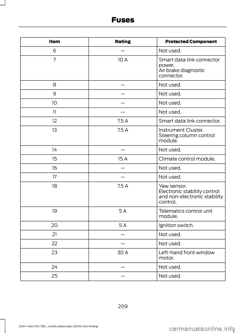
Protected ComponentRatingItem
Not used.—6
Smart data link connectorpower.10 A7
Air brake diagnosticconnector.
Not used.—8
Not used.—9
Not used.—10
Not used.—11
Smart data link connector.7.5 A12
Instrument Cluster.7.5 A13Steering column controlmodule.
Not used.—14
Climate control module.15 A15
Not used.—16
Not used.—17
Yaw sensor.7.5 A18Electronic stability controland non-electronic stabilitycontrol.
Telematics control unitmodule.5 A19
Ignition switch.5 A20
Not used.—21
Not used.—22
Left-hand front windowmotor.30 A23
Not used.—24
Not used.—25
209
2024 F-650/750 (TBC) , enUSA, Edition date: 202210, First-PrintingFuses
Page 235 of 386
We recommend the following actions afteroperating the vehicle up to 200 mi(320 km) in heavy snowfall or extremerain:
•Snow: At the earliest opportunity, openthe hood and clear all the snow and icefrom the air filter housing inlet. Do NOTremove the foam filter and reset theair filter restriction gauge.
•Extreme rain: The air filter dries afterabout 15–30 minutes at highwayspeeds. At the earliest opportunity,open the hood and reset the air filterrestriction gauge.
Air Filter Replacement
When replacing the air filter element, usea Motorcraft® air filter element. SeeMotorcraft Parts (page 293).
Note:Failure to use the correct air filterelement may result in severe enginedamage.
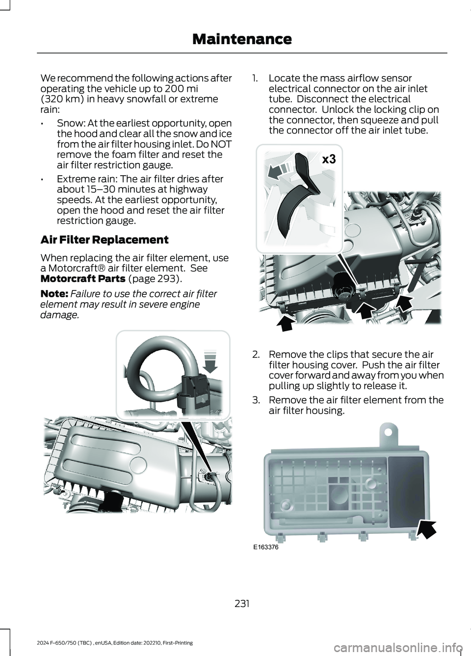
1.Locate the mass airflow sensorelectrical connector on the air inlettube. Disconnect the electricalconnector. Unlock the locking clip onthe connector, then squeeze and pullthe connector off the air inlet tube.
2.Remove the clips that secure the airfilter housing cover. Push the air filtercover forward and away from you whenpulling up slightly to release it.
3.Remove the air filter element from theair filter housing.
231
2024 F-650/750 (TBC) , enUSA, Edition date: 202210, First-PrintingMaintenanceE317651 x3E317652 E163376
Page 236 of 386
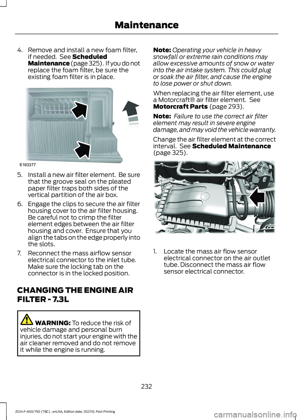
4.Remove and install a new foam filter,if needed. See ScheduledMaintenance (page 325). If you do notreplace the foam filter, be sure theexisting foam filter is in place.
5.Install a new air filter element. Be surethat the groove seal on the pleatedpaper filter traps both sides of thevertical partition of the air box.
6.Engage the clips to secure the air filterhousing cover to the air filter housing.Be careful not to crimp the filterelement edges between the air filterhousing and cover. Ensure that youalign the tabs on the edge properly intothe slots.
7.Reconnect the mass airflow sensorelectrical connector to the inlet tube.Make sure the locking tab on theconnector is in the locked position.
CHANGING THE ENGINE AIR
FILTER - 7.3L
WARNING: To reduce the risk ofvehicle damage and personal burninjuries, do not start your engine with theair cleaner removed and do not removeit while the engine is running.
Note:Operating your vehicle in heavysnowfall or extreme rain conditions mayallow excessive amounts of snow or waterinto the air intake system. This could plugor soak the air filter, and cause the engineto lose power or shut down.
When replacing the air filter element, usea Motorcraft® air filter element. SeeMotorcraft Parts (page 293).
Note: Failure to use the correct air filterelement may result in severe enginedamage, and may void the vehicle warranty.
Change the air filter element at the correctinterval. See Scheduled Maintenance(page 325).
1.Locate the mass air flow sensorelectrical connector on the air outlettube. Disconnect the mass air flowsensor electrical connector.
232
2024 F-650/750 (TBC) , enUSA, Edition date: 202210, First-PrintingMaintenanceE163377 E317615
Page 238 of 386
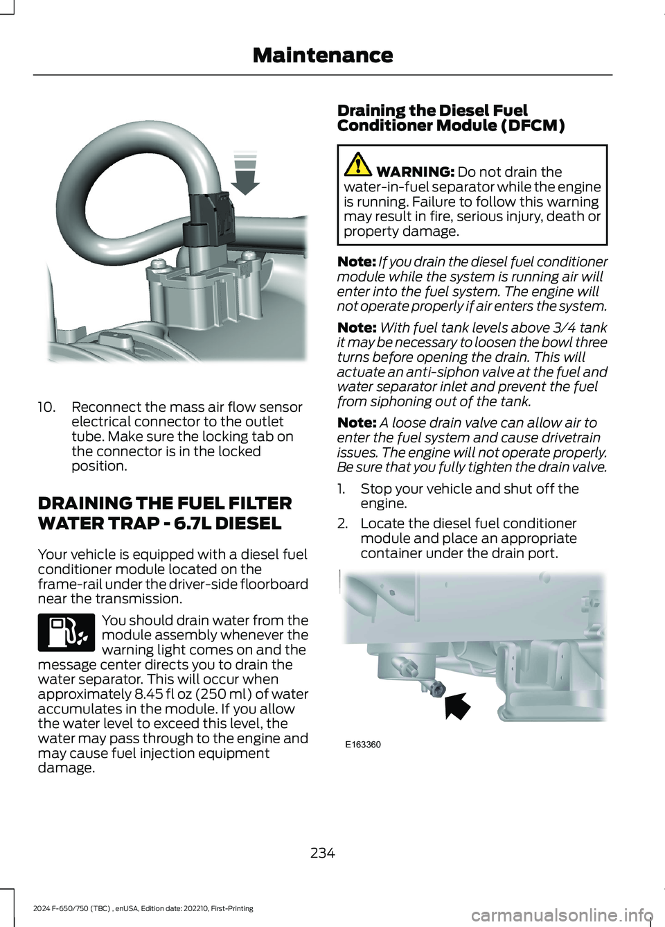
10.Reconnect the mass air flow sensorelectrical connector to the outlettube. Make sure the locking tab onthe connector is in the lockedposition.
DRAINING THE FUEL FILTER
WATER TRAP - 6.7L DIESEL
Your vehicle is equipped with a diesel fuelconditioner module located on theframe-rail under the driver-side floorboardnear the transmission.
You should drain water from themodule assembly whenever thewarning light comes on and themessage center directs you to drain thewater separator. This will occur whenapproximately 8.45 fl oz (250 ml) of wateraccumulates in the module. If you allowthe water level to exceed this level, thewater may pass through to the engine andmay cause fuel injection equipmentdamage.
Draining the Diesel FuelConditioner Module (DFCM)
WARNING: Do not drain thewater-in-fuel separator while the engineis running. Failure to follow this warningmay result in fire, serious injury, death orproperty damage.
Note:If you drain the diesel fuel conditionermodule while the system is running air willenter into the fuel system. The engine willnot operate properly if air enters the system.
Note:With fuel tank levels above 3⁄4 tankit may be necessary to loosen the bowl threeturns before opening the drain. This willactuate an anti-siphon valve at the fuel andwater separator inlet and prevent the fuelfrom siphoning out of the tank.
Note:A loose drain valve can allow air toenter the fuel system and cause drivetrainissues. The engine will not operate properly.Be sure that you fully tighten the drain valve.
1.Stop your vehicle and shut off theengine.
2.Locate the diesel fuel conditionermodule and place an appropriatecontainer under the drain port.
234
2024 F-650/750 (TBC) , enUSA, Edition date: 202210, First-PrintingMaintenanceE317619 E163360