instrument cluster FORD F650/750 2024 Owners Manual
[x] Cancel search | Manufacturer: FORD, Model Year: 2024, Model line: F650/750, Model: FORD F650/750 2024Pages: 386, PDF Size: 8.7 MB
Page 6 of 386
Automatic High Beam Control.................57
Direction Indicators......................................58
Interior Lamps................................................58
Windows and Mirrors
Power Windows............................................60
Exterior Mirrors................................................61
Interior Mirror..................................................63
Sun Visors........................................................63
Instrument Cluster
Gauges..............................................................64
Warning Lamps and Indicators................67
Audible Warnings and Indicators............70
Information Displays
General Information......................................71
Information Messages.................................75
Climate Control
Manual Climate Control.............................86
Hints on Controlling the Interior Climate...........................................................................87
Heated Exterior Mirrors...............................88
Seats
Sitting in the Correct Position..................89
Head Restraints.............................................89
Manual Seats...................................................91
Power Seats....................................................92
Rear Seats.......................................................94
Front Seat Armrest.......................................95
Rear Seat Armrest........................................95
Auxiliary Power Points
Auxiliary Power Points................................96
USB Ports
Locating the USB Ports..............................98
Playing Media Using the USB Port.........98
Charging a Device.........................................98
Storage Compartments
Overhead Console......................................100
Starting and Stopping theEngine
General Information....................................101
Ignition Switch...............................................101
Starting a Gasoline Engine......................102
Starting a Diesel Engine............................103
Switching Off the Engine.........................104
Engine Idle Shutdown...............................105
Engine Block Heater...................................105
Fuel and Refueling
Safety Precautions......................................107
Fuel Quality - Diesel...................................108
Fuel Quality - Gasoline................................111
Running Out of Fuel - Diesel.....................112
Running Out of Fuel - Gasoline...............112
Refueling - Diesel..........................................112
Refueling - Gasoline....................................114
Fuel Consumption........................................115
Fuel Tank Selector Switch........................116
Engine Emission Control
Emission Law..................................................117
Catalytic Converter......................................118
Selective Catalytic Reductant System -Diesel...........................................................120
Diesel Particulate Filter.............................124
Transmission
Automatic Transmission..........................130
Power Take-Off............................................135
Rear Axle
General Information...................................136
2
2024 F-650/750 (TBC) , enUSA, Edition date: 202210, First-PrintingTable of Contents
Page 9 of 386
Cleaning the Interior..................................265
Cleaning the Instrument Panel andInstrument Cluster Lens......................266
Repairing Minor Paint Damage.............266
Cleaning the Wheels.................................266
Vehicle Storage............................................267
Wheels and Tires
Tire Care.........................................................269
Using Snow Chains....................................287
Changing a Road Wheel..........................287
Technical Specifications.........................289
Capacities and Specifications
Engine Specifications - 6.7L Diesel.......291
Engine Specifications - 7.3L....................292
Motorcraft Parts - 6.7L Diesel................293
Motorcraft Parts - 7.3L..............................295
Bulb Specification Chart.........................296
Engine Oil Capacity and Specification -6.7L Diesel.................................................296
Engine Oil Capacity and Specification -7.3L...............................................................299
Cooling System Capacity andSpecification - 6.7L Diesel...................301
Cooling System Capacity andSpecification - 7.3L................................302
Fuel Tank Capacity - Diesel....................303
Fuel Tank Capacity - Gasoline..............304
Air Conditioning System Capacity andSpecification - 6.7L Diesel..................305
Air Conditioning System Capacity andSpecification - 7.3L................................306
Washer Fluid Specification....................306
Diesel Exhaust Fluid Capacity andSpecification............................................307
Automatic Transmission Fluid Capacityand Specification - Diesel...................307
Automatic Transmission Fluid Capacityand Specification - Gasoline.............308
Brake Fluid Specification........................309
Rear Axle Fluid Capacity andSpecification - Diesel...........................309
Rear Axle Fluid Capacity andSpecification - Gasoline.........................311
Hydraulic Power Steering Fluid Capacityand Specification.....................................312
Vehicle Identification
Vehicle Identification Number................313
Connected Vehicle
Connected Vehicle Requirements.........314
Connected Vehicle Limitations..............314
Connecting the Vehicle to a MobileNetwork.......................................................314
Connected Vehicle – Troubleshooting.........................................................................314
Audio System
General Information...................................315
Audio Unit.......................................................315
Connecting a Bluetooth® Device..........318
Streaming Bluetooth Audio.....................318
Playing Media From a USB Device........318
Audio Input Jack...........................................319
USB Port........................................................320
Using Voice Recognition..........................320
Accessories
Auxiliary Switches.......................................321
Ford Protect
Ford Protect..................................................323
Scheduled Maintenance
General Maintenance Information.......325
Normal Scheduled Maintenance.........330
Special Operating Conditions ScheduledMaintenance............................................335
5
2024 F-650/750 (TBC) , enUSA, Edition date: 202210, First-PrintingTable of Contents
Page 28 of 386
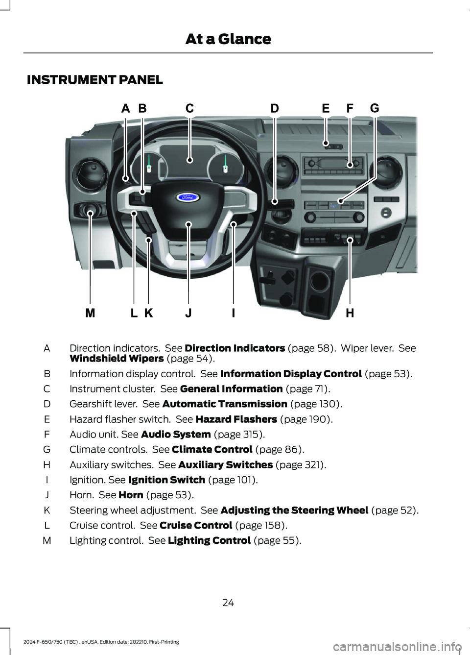
INSTRUMENT PANEL
Direction indicators. See Direction Indicators (page 58). Wiper lever. SeeWindshield Wipers (page 54).A
Information display control. See Information Display Control (page 53).B
Instrument cluster. See General Information (page 71).C
Gearshift lever. See Automatic Transmission (page 130).D
Hazard flasher switch. See Hazard Flashers (page 190).E
Audio unit. See Audio System (page 315).F
Climate controls. See Climate Control (page 86).G
Auxiliary switches. See Auxiliary Switches (page 321).H
Ignition. See Ignition Switch (page 101).I
Horn. See Horn (page 53).J
Steering wheel adjustment. See Adjusting the Steering Wheel (page 52).K
Cruise control. See Cruise Control (page 158).L
Lighting control. See Lighting Control (page 55).M
24
2024 F-650/750 (TBC) , enUSA, Edition date: 202210, First-PrintingAt a GlanceE307565
Page 54 of 386

Autolock repeats when:
•The vehicle is stopped.
•Any door opens and closes while theignition is on.
•The vehicle reaches a speed greaterthan 12 mph (20 km/h).
Autounlock
Autounlock unlocks all the doors when allof the following occur:
•All the doors are closed and yourvehicle is moving at a speed greaterthan 12 mph (20 km/h).
•Your vehicle comes to a stop.
•You open the driver door within 10minutes of switching the ignition off orto the accessory position.
Note:If you open the driver door after 10minutes, autounlock does not unlock allother doors.
Enabling or Disabling Autounlock
You can enable or disable the autounlockfeature in the instrument cluster display oran authorized dealer can do it for you.
To enable or disable autounlock, do thefollowing:
1.Switch the ignition on.
2.Press the power door unlock controlthree times.
3.Switch the ignition off.
4.Press the power door unlock controlthree times.
5.Switch the ignition on. The hornsounds indicating your vehicle is inprogramming mode.
6.Press the power door lock control andwithin five seconds, press the powerdoor unlock control. The horn soundsonce if disabled or twice if enabled.
7.Switch the ignition off. The horn soundsindicating programming is complete.
Note:You can also switch this feature onor off using the instrument cluster display.See Information Displays (page 71).
Illuminated Entry
The interior lamps and select exteriorlamps illuminate when you unlock thedoors with the remote entry system.
The illuminated entry system turns off thelights if:
•The ignition is on.
•You press the remote control lockbutton.
•25 seconds have passed.
The dome lamp does not turn on if thecontrol is in the off position.
The lights do not turn off if:
•You turn them on with the dimmercontrol.
•Any door is open.
Battery Saver
The battery saver turns off the interiorlamps 10 minutes after you switch theignition off if a door is open and the domelamp switch is on. It turns off the interiorlamps after 10 minutes if the dome lampswitch is off.
50
2024 F-650/750 (TBC) , enUSA, Edition date: 202210, First-PrintingDoors and Locks
Page 68 of 386
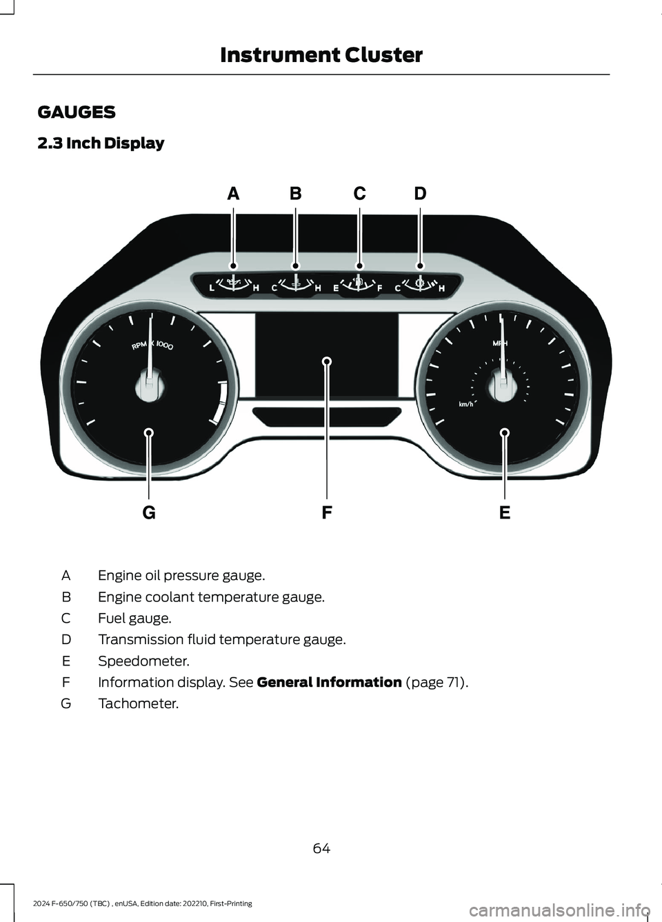
GAUGES
2.3 Inch Display
Engine oil pressure gauge.A
Engine coolant temperature gauge.B
Fuel gauge.C
Transmission fluid temperature gauge.D
Speedometer.E
Information display. See General Information (page 71).F
Tachometer.G
64
2024 F-650/750 (TBC) , enUSA, Edition date: 202210, First-PrintingInstrument ClusterE219638
Page 69 of 386
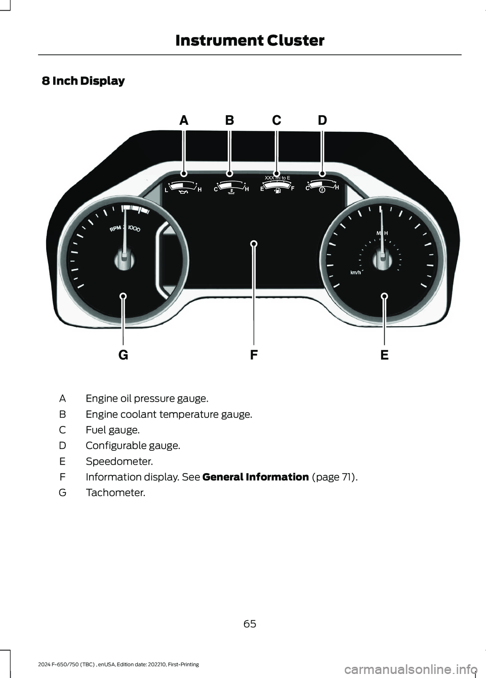
8 Inch Display
Engine oil pressure gauge.A
Engine coolant temperature gauge.B
Fuel gauge.C
Configurable gauge.D
Speedometer.E
Information display. See General Information (page 71).F
Tachometer.G
65
2024 F-650/750 (TBC) , enUSA, Edition date: 202210, First-PrintingInstrument ClusterE299699
Page 70 of 386
Engine Oil Pressure Gauge
Indicates engine oil pressure. At normaloperating temperature, the level indicatoris in the normal range. If the pressure gaugefalls below the normal range, stop yourvehicle, switch off the engine and checkthe engine oil level. Add oil if needed. If theoil level is correct, have your vehiclechecked by an authorized dealer.
Engine Coolant TemperatureGauge
WARNING: Do not remove thecoolant reservoir cap when the engine ison or the cooling system is hot. Wait 10minutes for the cooling system to cooldown. Cover the coolant reservoir capwith a thick cloth to prevent thepossibility of scalding and slowly removethe cap. Failure to follow this instructioncould result in personal injury.
Indicates engine coolant temperature. Atnormal operating temperature, the levelindicator is in the normal range. If theengine coolant temperature exceeds thenormal range, stop your vehicle as soon aspossible, switch off the engine and let theengine cool.
Fuel Gauge
The fuel gauge indicates about how muchfuel is in the fuel tank.
The arrow adjacent to the fuel pumpsymbol indicates on which side of yourvehicle the fuel filler door is located.
Note:The fuel gauge may vary slightlywhen your vehicle is moving or on a slope.
Low Fuel Reminder
A low fuel level reminder displays andsounds when the distance to emptyreaches 50 mi (80 km),25 mi (40 km),10 mi (20 km) and 0 mi (0 km) for allvehicle keys.
Note:The low fuel reminder can appear atdifferent fuel gauge positions depending onfuel economy conditions. This variation isnormal.
Distance to Empty
Indicates the approximate distance yourvehicle can travel on the fuel remaining inthe tank. Changes in driving pattern cancause the value to not only decrease butalso increase or stay constant for periodsof time.
Configurable Gauge
Transmission Fluid Temperature Gauge
Indicates transmission fluid temperature.At normal operating temperature, the levelindicator is in the normal range. If thetransmission fluid temperature exceedsthe normal range, stop your vehicle as soonas possible and verify the airflow is notrestricted by snow or debris blockingairflow through the grille.
Special operating conditions such assnowplowing, towing, or off-road use maycause higher than normal operatingtemperatures. See Special OperatingConditions Scheduled Maintenance(page 335).
To lower the transmission temperatureinto the normal range, alter the severity ofyour driving conditions. Operating thetransmission for extended periods with thegauge in the higher than normal area maycause internal transmission damage. If thegauge continues to show hightemperatures, see an authorized dealer.
66
2024 F-650/750 (TBC) , enUSA, Edition date: 202210, First-PrintingInstrument Cluster
Page 71 of 386
Diesel Exhaust Fluid Gauge
Indicates the fluid level in the dieselexhaust fluid (DEF) tank.
Voltmeter
Displays electrical system voltage.
WARNING LAMPS AND
INDICATORS
The following warning lamps andindicators alert you to a vehicle conditionthat may become serious. Some lampsilluminate when you start your vehicle tomake sure they work. If any lamps remainon after starting your vehicle, refer to therespective system warning lamp for furtherinformation.
Note:Some warning indicators appear inthe information display and operate thesame as a warning lamp but do notilluminate when you start your vehicle.
Anti-Lock Braking System
If it illuminates when you aredriving, this indicates amalfunction. Your vehiclecontinues to have normal braking withoutthe anti-lock brake system function. Haveyour vehicle checked as soon as possible.
Automatic Regeneration Control
(If Equipped)
Illuminates when you switch itoff.
Battery
If it illuminates when driving, itindicates a malfunction. Switchoff all unnecessary electricalequipment and have the systemimmediately checked.
Brake System
WARNING: Driving your vehiclewith the warning lamp on is dangerous.A significant decrease in brakingperformance may occur. It may take youlonger to stop your vehicle. Have yourvehicle checked as soon as possible.Driving extended distances with theparking brake engaged can cause brakefailure and the risk of personal injury.
Indicates low brake fluid level ora brake system malfunction.Have the system immediatelychecked.
Check Suspension (If Equipped)
Illuminates when you press theair suspension dump switch.
Cruise Control
Illuminates when you switch onthis feature. See What Is CruiseControl (page 158).
Diesel Exhaust Fluid (If Equipped)
Illuminates with the key in theON position, when the fluid iscontaminated or the level fallsbelow 1.0 gal (3.8 L). Refill the tank or, ata minimum, add at least 1.0 gal (3.8 L) inthe tank.
Direction Indicator
Illuminates when you switch onthe left or right directionindicator, or when you switch onthe hazard warning flashers. Check for aburned out bulb if the indicators stay on orflash faster.
67
2024 F-650/750 (TBC) , enUSA, Edition date: 202210, First-PrintingInstrument ClusterE67020 E208811 E67021 E209041 E208808 E71340 E163176 E67018
Page 72 of 386
Door Ajar
Displays when the ignition is onand any door is not completelyclosed.
Electronic Locking Differential (If
Equipped)
Illuminates when using theelectronic locking differential.
Engine Coolant Temperature
If it illuminates when your vehicleis moving, this indicates that theengine is overheating. Stop yourvehicle as soon as it is safe to do so andswitch the engine off. Have your vehiclechecked as soon as possible. See EngineCoolant Check (page 238).idk
Engine Oil Pressure
If it illuminates with the enginerunning, or when you are driving,this indicates a malfunction.Stop your vehicle as soon as it is safe todo so and switch off the engine. Check theengine oil level.
Note:Do not resume your journey if itilluminates despite the level being correct.Have the system checked as soon aspossible.
Exhaust Brake On (If Equipped)
The exhaust brake indicator lightilluminates when you switch theexhaust brake on.
Fasten Seatbelt
Illuminates and a tone soundsto remind you to fasten yourseatbelt.
High Beam
Illuminates when you switch onthe high beam headlamps. Itflashes when you use theheadlamp flasher.
Hydromax
If the light illuminates andremains on when the key is in theon position or the engine isrunning, this indicates inadequate hydraulicbooster pressure or reserve pump systemfailure. Stop the vehicle as soon aspossible and have your vehicle checked.
Low Fuel Level
Illuminates when the fuel levelis low or the fuel tank is nearlyempty. Refuel as soon aspossible.
Parking Brake Warning
Briefly illuminates when youswitch the ignition to the onposition, with the engine off. Italso illuminates when you apply theparking brake. If the park brake lamp doesnot illuminate at these times, seekimmediate service. Vehicles with the powerparking brake option: If the park brakewarning lamp begins to blink after settingthe parking brake, this may indicate afailure in the parking brake system. Havethe system checked as soon as possible.Driving extended distances with theparking brake engaged can cause brakefailure and the risk of personal injury.
Parking Lamps
Illuminates when you switch thelow beam headlamps or theparking lamps on.
68
2024 F-650/750 (TBC) , enUSA, Edition date: 202210, First-PrintingInstrument Cluster E163170 E103308 E67022 E171217 E71880 E67019 E146190 E208810 E71341
Page 73 of 386
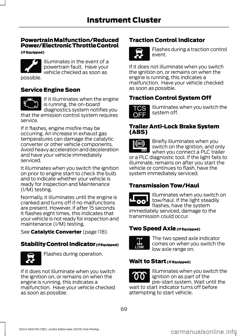
Powertrain Malfunction/ReducedPower/Electronic Throttle Control
(If Equipped)
Illuminates in the event of apowertrain fault. Have yourvehicle checked as soon aspossible.
Service Engine Soon
If it illuminates when the engineis running, the on-boarddiagnostics system notifies youthat the emission control system requiresservice.
If it flashes, engine misfire may beoccurring. An increase in exhaust gastemperatures can damage the catalyticconverter or other vehicle components.Avoid heavy acceleration and decelerationand have your vehicle immediatelyserviced.
It illuminates when you switch the ignitionon prior to engine start to check the bulband to indicate whether your vehicle isready for Inspection and Maintenance(I/M) testing.
Normally, it illuminates until the engine iscranked and turns off if no malfunctionsare present. However, if after 15 secondsit flashes eight times, this indicates thatyour vehicle is not ready for inspection andmaintenance (I/M) testing.
See Catalytic Converter (page 118).
Stability Control Indicator (If Equipped)
Flashes during operation.
If it does not illuminate when you switchthe ignition on, or remains on when theengine is running, this indicates amalfunction. Have your vehicle checkedas soon as possible.
Traction Control Indicator
Flashes during a traction controlevent.
If it does not illuminate when you switchthe ignition on, or remains on when theengine is running, this indicates amalfunction. Have your vehicle checkedas soon as possible.
Traction Control System Off
Illuminates when you switch thesystem off.
Trailer Anti-Lock Brake System(ABS)
Briefly illuminates when youswitch on the ignition, and onlywhen you connect a PLC traileror a PLC diagnostic tool. If the light fails toilluminate, remains on after you start thevehicle or continues to flash, have thesystem immediately serviced.
Transmission Tow/Haul
Illuminates when you switch ontow/haul. If the light steadilyflashes, have the systemimmediately serviced, damage to thetransmission could occur.
Two Speed Axle (If Equipped)
The two speed axle indicatorcomes on when you switch thelow axle range on.
Wait to Start (If Equipped)
Illuminates when you switch theignition on as part of thepre-start system. Wait until thewait to start indicator turns off beforeattempting to start vehicle.
69
2024 F-650/750 (TBC) , enUSA, Edition date: 202210, First-PrintingInstrument Cluster E67028 E138639 E138639 E194301 E209040 E246592 E208809