brake light FORD F750 2004 11.G Owner's Manual
[x] Cancel search | Manufacturer: FORD, Model Year: 2004, Model line: F750, Model: FORD F750 2004 11.GPages: 264, PDF Size: 1.47 MB
Page 115 of 264
9. Charge the trailer brake system. Set the trailer brakes, either with the
hand valve or tractor protection valve. Pull against the trailer for an
additional check of proper hook-up. Do not pull hard enough to damage
or strain the equipment.
10. Set the tractor parking brakes and fully raise the trailer landing gear.
Refer toBrakesin this chapter for proper operation of the parking brake
and trailer brakes.
11. Check the operation of all trailer lights and correct any lights that
may be faulty.
Un-hook
1. Try to keep the tractor and trailer in a straight line.
2. Apply the parking brakes.
3. Lower the trailer landing gear, making sure it is on solid, level ground.
The weight of the trailer is to be on the landing gear.
4. Block the trailer wheels.
5. Disconnect the brake hoses and light cords. Be sure hoses and cords
are clear.
6. Pull coupler release lever to disengage the fifth wheel jaws.
7. Release the tractor parking brakes.
8. Pull out from the trailer slowly, allowing the landing gear to take the
load gradually.
AUTOMATIC TRANSMISSION OPERATION (IF EQUIPPED)
Main transmission, auxiliary transmission, transfer case and power
take-off (PTO) control shift patterns can be found on a placard or decal
on the driver’s sun visor, on the instrument panel or on the shift control
itself.
The main transmission control is used to select the various gear ratios or
speeds of the transmission. Selecting D (Direct Drive), does not change
the transmission gear ratio, but is used where the gear ratios in the main
transmission are adequate to handle the vehicle operation.
Hold the brake pedal down while you move the gearshift lever
between positions. If you don’t hold the brake pedal down, your
vehicle may move unexpectedly and cause property damage, personal
injury or death.
Allison 2000 automatic transmission
This transmission is available with a column-mounted gearshift lever. The
gear positions are displayed on the RNDL in the instrument cluster.
2004 F650/750(f67)
Supplement
USA English(fus)
Driving
115
Page 118 of 264

If engagement is prevented by the gear teeth not meshing properly,
release the brakes and allow the vehicle to creep slightly - or shift the
selector to N (Neutral) and then back in gear. The PTO should never be
engaged by clashing the gear teeth. This may damage the PTO unit and
the transmission PTO drive gear teeth. This could result in further
damage to the transmission and PTO.
PTO operation with vehicle stationary
To operate the power take-off, stop the vehicle, idle the engine and set
the parking brake. Make sure the gear selector is in any forward drive
range, then engage the PTO. After the PTO is engaged for stationary
vehicle operation, move the range selector to N (Neutral). Increase the
engine speed until the desired power take-off operation speed is
obtained. To disengage the PTO after operation with the vehicle
standing, release the throttle, allow the drive equipment to come to a
stop, and then disengage the PTO.
When the PTO is operated with the vehicle stationary, the
transmission must be placed in N (Neutral) with the parking
brake set. If the transmission is not in N (Neutral) and is equipped
with a remote throttle control, an increase in engine speed can
overpower the parking brake and cause the vehicle to move, possibly
resulting in personal and/or property damage.
PTO operation while vehicle is moving
After the PTO is engaged for driven vehicle operation, shift to the
desired range and drive the vehicle. The speed of the PTO, during this
period of operation, will always maintain direct relation to vehicle speed.
PTO speed will decrease in relation to vehicle (transmission output)
speed as shifts to a higher gear occur. When operating the PTO while the
vehicle is moving, the PTO may be disengaged whenever it is no longer
required. When there is no load on the PTO gear, it can be pulled out of
engagement.
Power take-off (PTO) operation on vehicles equipped with a
Caterpillar engine
If your vehicle is equipped with a Caterpillar engine, the PTO will only
operate if the vehicle is in Neutral. This feature can be overridden by a
special service tool; see your dealer or service representative for more
information.
2004 F650/750(f67)
Supplement
USA English(fus)
Driving
118
Page 120 of 264
If your vehicle’s transmission is equipped with a ceramic clutch, you
must start the vehicle moving in first gear and engage the clutch before
pressing the accelerator at idle. Also, don’t try to slip the clutch by
raising engine RPM and riding or feathering the clutch pedal since the
vehicle will experience erratic engagement. Erratic engagement can
cause the engine stalling and potential serious damage to the vehicle’s
driveline components.
Clutch brake (vehicles equipped with a non-synchronized
transmission) - Vehicle stationary
A clutch brake is used to stop the transmission input shaft rotation so
that the initial 1 (First) or R (Reverse) gear selection can be
accomplished when the vehicle is stationary and the engine is running at
idle speed. Clutch brake application occurs in the last 25 mm (one inch)
of clutch pedal travel.
When using the clutch brake, fully depress the clutch pedal and shift the
transmission into 1 (First) or R (Reverse). If the transmission won’tgo
into one of these gears, slowly release the clutch pedal while applying
light pressure on the transmission shift lever until it shifts into gear.
Note:After engagement of 1 (First) gear,do notuse the clutch brake
for upshifting or downshifting. If you do, clutch brake life will shorten
and gear selection shift efforts may increase.
Double-clutch procedures - vehicles equipped with a
non-synchronized transmission
In order to properly upshift or downshift, perform the following steps:
1. Depress the clutch pedal to disengage the clutch.
2. Shift the transmission in to neutral.
3. Release the clutch pedal.
If upshifting, wait until the engine speed matches the transmission
speed of the gear you are selecting.
If downshifting,accelerate the engine until the engine speed matches
the input speed of the gear you are selecting. Depress the clutch pedal
immediately and shift into the desired gear, then release the clutch
pedal.
2004 F650/750(f67)
Supplement
USA English(fus)
Driving
120
Page 122 of 264
Shifting with a synchronized transmission
With the clutch pedal depressed, use 2 (Second) gear synchronizer to
stop the clutch disc rotation; this allows smooth engagement of 1 (First)
or R (Reverse) To complete the gear engagement, it may be necessary to
apply light pressure to the gearshift lever during initial engagement of
the clutch. It takes a second or two to match gear speeds; steady
pressure on the gearshift lever will help the synchronizer perform its job
more quickly. If the gearshift lever is forced into position, this action
defeats the purpose of the synchronizer by causing gear clash.
Shifting with a non-synchronized transmission
Refer toClutch brakeandDouble clutch proceduresin theClutch
section of this chapter.
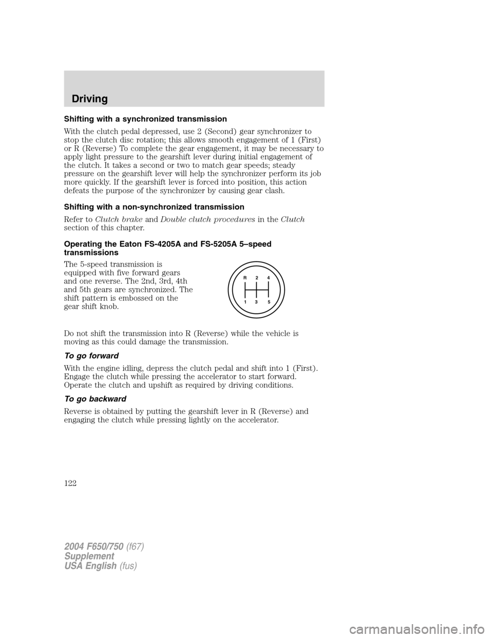
Operating the Eaton FS-4205A and FS-5205A 5–speed
transmissions
The 5-speed transmission is
equipped with five forward gears
and one reverse. The 2nd, 3rd, 4th
and 5th gears are synchronized. The
shift pattern is embossed on the
gear shift knob.
Do not shift the transmission into R (Reverse) while the vehicle is
moving as this could damage the transmission.
To go forward
With the engine idling, depress the clutch pedal and shift into 1 (First).
Engage the clutch while pressing the accelerator to start forward.
Operate the clutch and upshift as required by driving conditions.
To go backward
Reverse is obtained by putting the gearshift lever in R (Reverse) and
engaging the clutch while pressing lightly on the accelerator.
R 2 4
3 5 1
2004 F650/750(f67)
Supplement
USA English(fus)
Driving
122
Page 132 of 264
•Canada
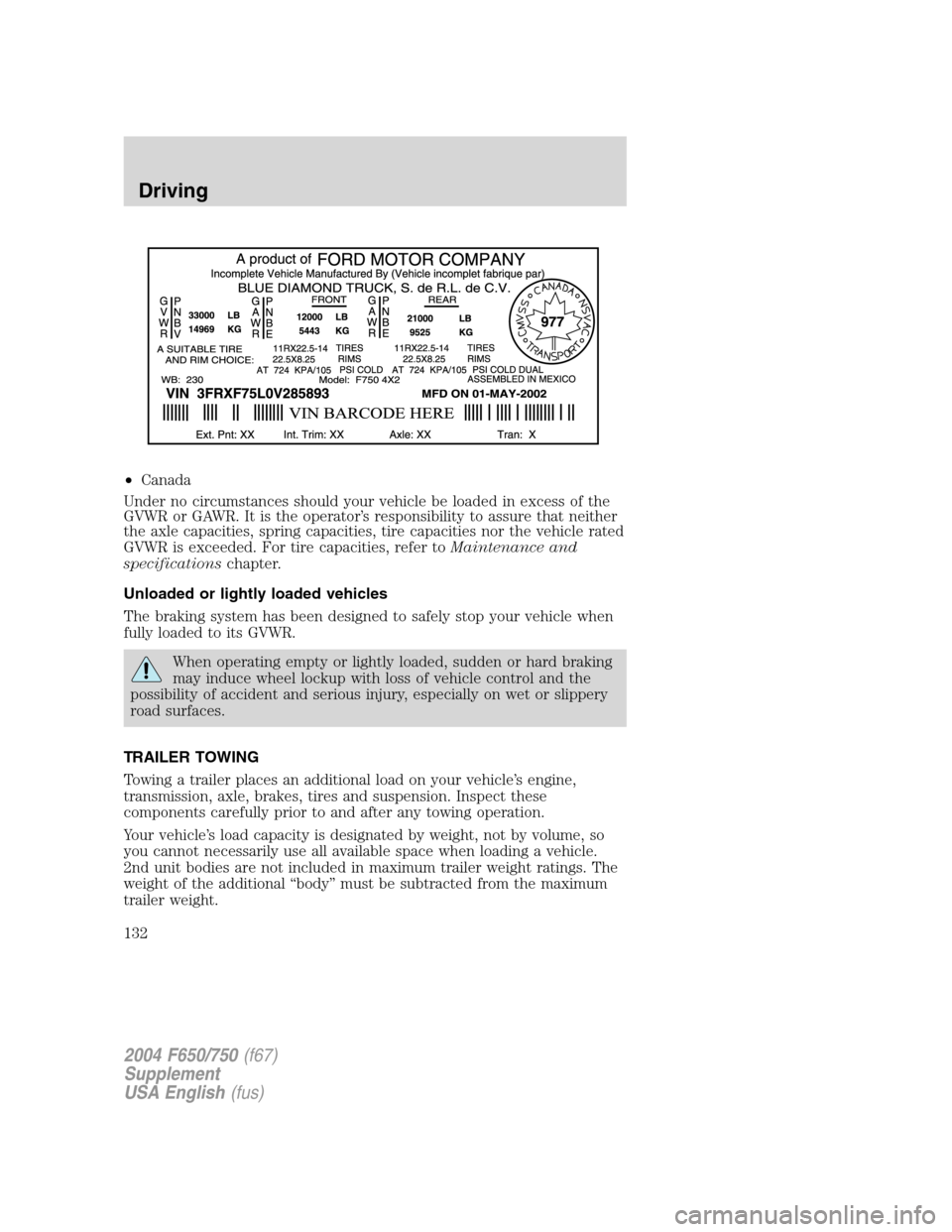
Under no circumstances should your vehicle be loaded in excess of the
GVWR or GAWR. It is the operator’s responsibility to assure that neither
the axle capacities, spring capacities, tire capacities nor the vehicle rated
GVWR is exceeded. For tire capacities, refer toMaintenance and
specificationschapter.
Unloaded or lightly loaded vehicles
The braking system has been designed to safely stop your vehicle when
fully loaded to its GVWR.
When operating empty or lightly loaded, sudden or hard braking
may induce wheel lockup with loss of vehicle control and the
possibility of accident and serious injury, especially on wet or slippery
road surfaces.
TRAILER TOWING
Towing a trailer places an additional load on your vehicle’s engine,
transmission, axle, brakes, tires and suspension. Inspect these
components carefully prior to and after any towing operation.
Your vehicle’s load capacity is designated by weight, not by volume, so
you cannot necessarily use all available space when loading a vehicle.
2nd unit bodies are not included in maximum trailer weight ratings. The
weight of the additional“body”must be subtracted from the maximum
trailer weight.
2004 F650/750(f67)
Supplement
USA English(fus)
Driving
132
Page 134 of 264
Trailer brakes
Electric brakes and manual, automatic or surge-type trailer brakes are
safe if installed properly and adjusted to the manufacturer’s
specifications. The trailer brakes must meet local and Federal
regulations.
Do not connect a trailer’s hydraulic brake system directly to your
vehicle’s brake system. Your vehicle may not have enough
braking power and your chances of having a collision greatly increase.
Trailer lamps
Trailer lamps are required on most towed vehicles. Your vehicle may be
equipped with one of two possible trailer wiring designs. Make sure all
running lights, brake lights, turn signals and hazard lights are working.
See your dealer or trailer rental agency for proper instructions and
equipment for hooking up trailer lamps.
Driving while you tow
When towing a trailer:
•Turn off the speed control. The speed control may shut off
automatically when you are towing on long, steep grades.
•Consult your local motor vehicle speed regulations for towing a trailer.
•To eliminate excessive transmission shifting, use a lower gear. This will
also assist in transmission cooling.
•Anticipate stops and brake gradually.
•Do not exceed the GCWR rating or transmission damage may occur.
Servicing after towing
If you tow a trailer for long distances, your vehicle will require more
frequent service intervals. Refer to your scheduled maintenance guide for
more information.
Trailer towing tips
•Practice turning, stopping and backing up before starting on a trip to
get the feel of the vehicle trailer combination. When turning, make
wider turns so the trailer wheels will clear curbs and other obstacles.
•Allow more distance for stopping with a trailer attached.
•The trailer tongue weight should be 10–15% of the loaded trailer
weight.
2004 F650/750(f67)
Supplement
USA English(fus)
Driving
134
Page 138 of 264
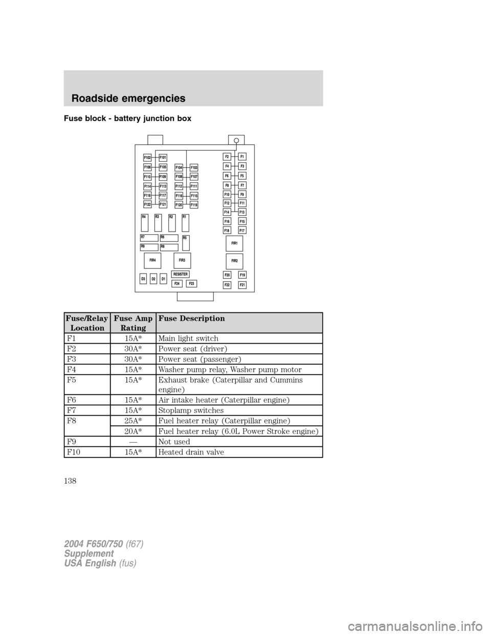
Fuse block - battery junction box
Fuse/Relay
LocationFuse Amp
RatingFuse Description
F1 15A* Main light switch
F2 30A* Power seat (driver)
F3 30A* Power seat (passenger)
F4 15A* Washer pump relay, Washer pump motor
F5 15A* Exhaust brake (Caterpillar and Cummins
engine)
F6 15A* Air intake heater (Caterpillar engine)
F7 15A* Stoplamp switches
F8 25A* Fuel heater relay (Caterpillar engine)
20A* Fuel heater relay (6.0L Power Stroke engine)
F9—Not used
F10 15A* Heated drain valve
2004 F650/750(f67)
Supplement
USA English(fus)
Roadside emergencies
138
Page 139 of 264
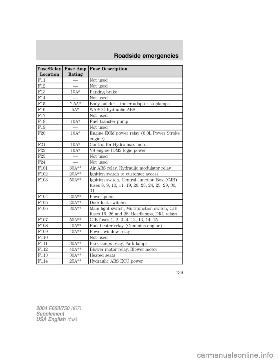
Fuse/Relay
LocationFuse Amp
RatingFuse Description
F11—Not used
F12—Not used
F13 10A* Parking brake
F14—Not used
F15 7.5A* Body builder - trailer adapter stoplamps
F16 5A* WABCO hydraulic ABS
F17—Not used
F18 10A* Fuel transfer pump
F19—Not used
F20 10A* Engine ECM power relay (6.0L Power Stroke
engine)
F21 10A* Control for Hydro-max motor
F22 10A* V8 engine IDM2 logic power
F23—Not used
F24—Not used
F101 30A** Air ABS relay, Hydraulic modulator relay
F102 20A** Ignition switch to customer access
F103 50A** Ignition switch, Central Junction Box (CJB)
fuses 8, 9, 10, 11, 19, 20, 23, 24, 25, 29, 30,
31
F104 20A** Power point
F105 20A** Door lock switches
F106 30A** Main light switch, Multifunction switch, CJB
fuses 16, 26 and 28, Headlamps, DRL relays
F107 50A** CJB fuses 1, 2, 3, 4, 12, 13, 14, 15
F108 40A** Fuel heater relay (Cummins engine)
F109 40A** Power window relay
F110—Not used
F111 30A** Park lamps relay, Park lamps
F112 40A** Blower motor relay, Blower motor
F113 30A** Heated seats
F114 25A** Hydraulic ABS ECU power
2004 F650/750(f67)
Supplement
USA English(fus)
Roadside emergencies
139
Page 142 of 264
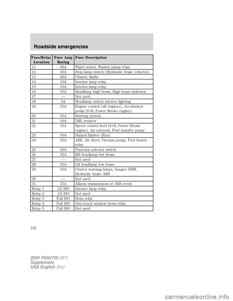
Fuse/Relay
LocationFuse Amp
RatingFuse Description
11 30A Wiper motor, Washer pump relay
12 10A Stop lamp switch (Hydraulic brake vehicles)
13 20A Cluster, Radio
14 10A Interior lamp relay
15 10A Interior lamp relay
16 15A Headlamp high beam, High beam indicator
17—Not used
18 5A Headlamp switch interior lighting
19 15A Engine control (all engines), Accelerator
pedal (6.0L Power Stroke engine)
20 15A Starting system
21 10A DRL resistor
22 15A Speed control feed (6.0L Power Stroke
engine), Air solenoid, Fuel transfer pump
23 10A Hazard flasher (Run)
24 15A ABS, Air dryer, Vacuum pump, Fuel heater
relay
25 10A Function selector switch
26 10A RH headlamp low beam
27—Not used
28 10A LH headlamp low beam
29 10A Cluster warning lamps, Gauges GEM,
Hydraulic brake ABS
30—Not used
31 15A Allison transmission or ABS event
Relay 1 1/2 ISO Interior lamp relay
Relay 2 1/2 ISO Not used
Relay 3 Full ISO Horn relay
Relay 4 Full ISO One-touch window down relay
Relay 5 Full ISO Not used
2004 F650/750(f67)
Supplement
USA English(fus)
Roadside emergencies
142
Page 203 of 264
Prior to re-installing rear aluminum hub-piloted wheels, clean each wheel
locator pad on the hub from all dirt, rust and foreign material. Apply a
light coat of chassis grease, never-seize or disc brake corrosion control
grease, only to the wheel locator pad.
When installing the tire and rim assembly on disc-brake equipped axles,
make sure the tire valve stem clears the brake caliper. The use of a tire
manufacturer’s stem forming tool is the only acceptable method of
obtaining clearance when necessary.
Note:Always observe the following instructions:
•Always loosen rim clamps before complete removal of nut from stud
(cast spoke wheels). With loosened nuts on stud, strike clamps with a
heavy hammer and be sure each clamp is loose.
•Always deflate tires completely before removing locks or side rings.
•Always inflate tires in a safety cage.
•Never mix rim side rings or lock rings of different types,
manufacturers or sizes.
•Never use cracked, bent or badly rusted parts.
•Never re-inflate flat tires on-vehicle; use the spare tire.
•Never add air until each side ring or lock ring is fully seated.
•Never hammer side ring or lock ring on a partially- or fully-inflated
tire.
Failure to follow these instructions could result in property
damage, personal injury or death
Proper torque
It is important to tighten and maintain wheel and rim mounting nuts to
the proper torque. Loose nuts or over-tightened nuts can lead to
premature wear and possible failure of the wheel and/or mounting
hardware.
2004 F650/750(f67)
Supplement
USA English(fus)
Maintenance and specifications
203