fuel pump FORD F750 2004 11.G Owners Manual
[x] Cancel search | Manufacturer: FORD, Model Year: 2004, Model line: F750, Model: FORD F750 2004 11.GPages: 264, PDF Size: 1.47 MB
Page 6 of 264
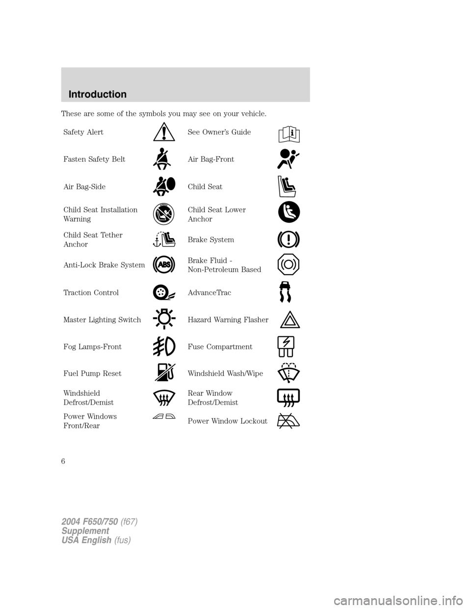
These are some of the symbols you may see on your vehicle.
Safety Alert
See Owner’s Guide
Fasten Safety BeltAir Bag-Front
Air Bag-SideChild Seat
Child Seat Installation
WarningChild Seat Lower
Anchor
Child Seat Tether
AnchorBrake System
Anti-Lock Brake SystemBrake Fluid -
Non-Petroleum Based
Traction ControlAdvanceTrac
Master Lighting SwitchHazard Warning Flasher
Fog Lamps-FrontFuse Compartment
Fuel Pump ResetWindshield Wash/Wipe
Windshield
Defrost/DemistRear Window
Defrost/Demist
Power Windows
Front/RearPower Window Lockout
2004 F650/750(f67)
Supplement
USA English(fus)
Introduction
6
Page 23 of 264
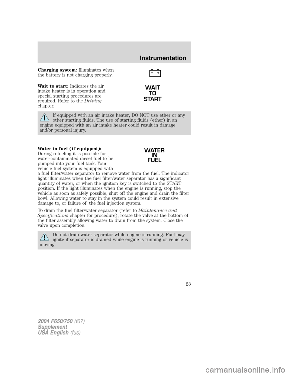
Charging system:Illuminates when
the battery is not charging properly.
Wait to start:Indicates the air
intake heater is in operation and
special starting procedures are
required. Refer to theDriving
chapter.
If equipped with an air intake heater, DO NOT use ether or any
other starting fluids. The use of starting fluids (ether) in an
engine equipped with an air intake heater could result in damage
and/or personal injury.
Water in fuel (if equipped):
During refueling it is possible for
water-contaminated diesel fuel to be
pumped into your fuel tank. Your
vehicle fuel system is equipped with
a fuel filter/water separator to remove water from the fuel. The indicator
light illuminates when the fuel filter/water separator has a significant
quantity of water, or when the ignition key is switched to the START
position. If the light illuminates when the engine is running, stop the
vehicle as soon as safely possible, shut off the engine and drain the filter
bowl. Allowing water to stay in the system could result in extensive
damage to, or failure of, the fuel injection system.
To drain the fuel filter/water separator (refer toMaintenance and
Specificationschapter for procedure), rotate the valve at the bottom of
the filter assembly allowing water to drain from the system. Close the
valve upon completion.
Do not drain water separator while engine is running. Fuel may
ignite if separator is drained while engine is running or vehicle is
moving.
WAIT
TO
START
WATER
IN
FUEL
2004 F650/750(f67)
Supplement
USA English(fus)
Instrumentation
23
Page 27 of 264
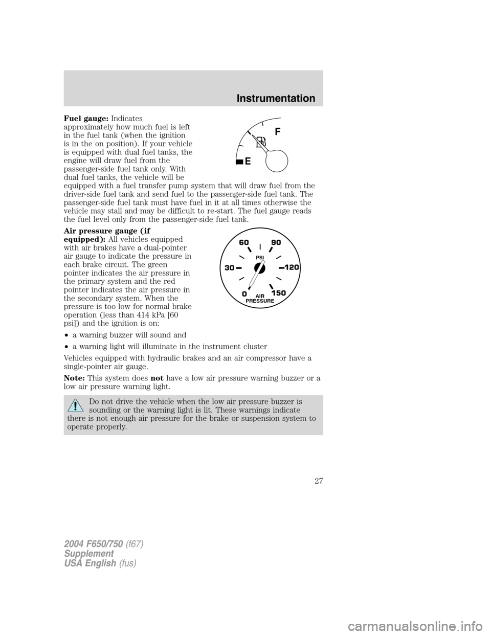
Fuel gauge:Indicates
approximately how much fuel is left
in the fuel tank (when the ignition
is in the on position). If your vehicle
is equipped with dual fuel tanks, the
engine will draw fuel from the
passenger-side fuel tank only. With
dual fuel tanks, the vehicle will be
equipped with a fuel transfer pump system that will draw fuel from the
driver-side fuel tank and send fuel to the passenger-side fuel tank. The
passenger-side fuel tank must have fuel in it at all times otherwise the
vehicle may stall and may be difficult to re-start. The fuel gauge reads
the fuel level only from the passenger-side fuel tank.
Air pressure gauge (if
equipped):All vehicles equipped
with air brakes have a dual-pointer
air gauge to indicate the pressure in
each brake circuit. The green
pointer indicates the air pressure in
the primary system and the red
pointer indicates the air pressure in
the secondary system. When the
pressure is too low for normal brake
operation (less than 414 kPa [60
psi]) and the ignition is on:
•a warning buzzer will sound and
•a warning light will illuminate in the instrument cluster
Vehicles equipped with hydraulic brakes and an air compressor have a
single-pointer air gauge.
Note:This system doesnothave a low air pressure warning buzzer or a
low air pressure warning light.
Do not drive the vehicle when the low air pressure buzzer is
sounding or the warning light is lit. These warnings indicate
there is not enough air pressure for the brake or suspension system to
operate properly.
0 30120 90 60
150AIR
PRESSURE
PSI
2004 F650/750(f67)
Supplement
USA English(fus)
Instrumentation
27
Page 138 of 264
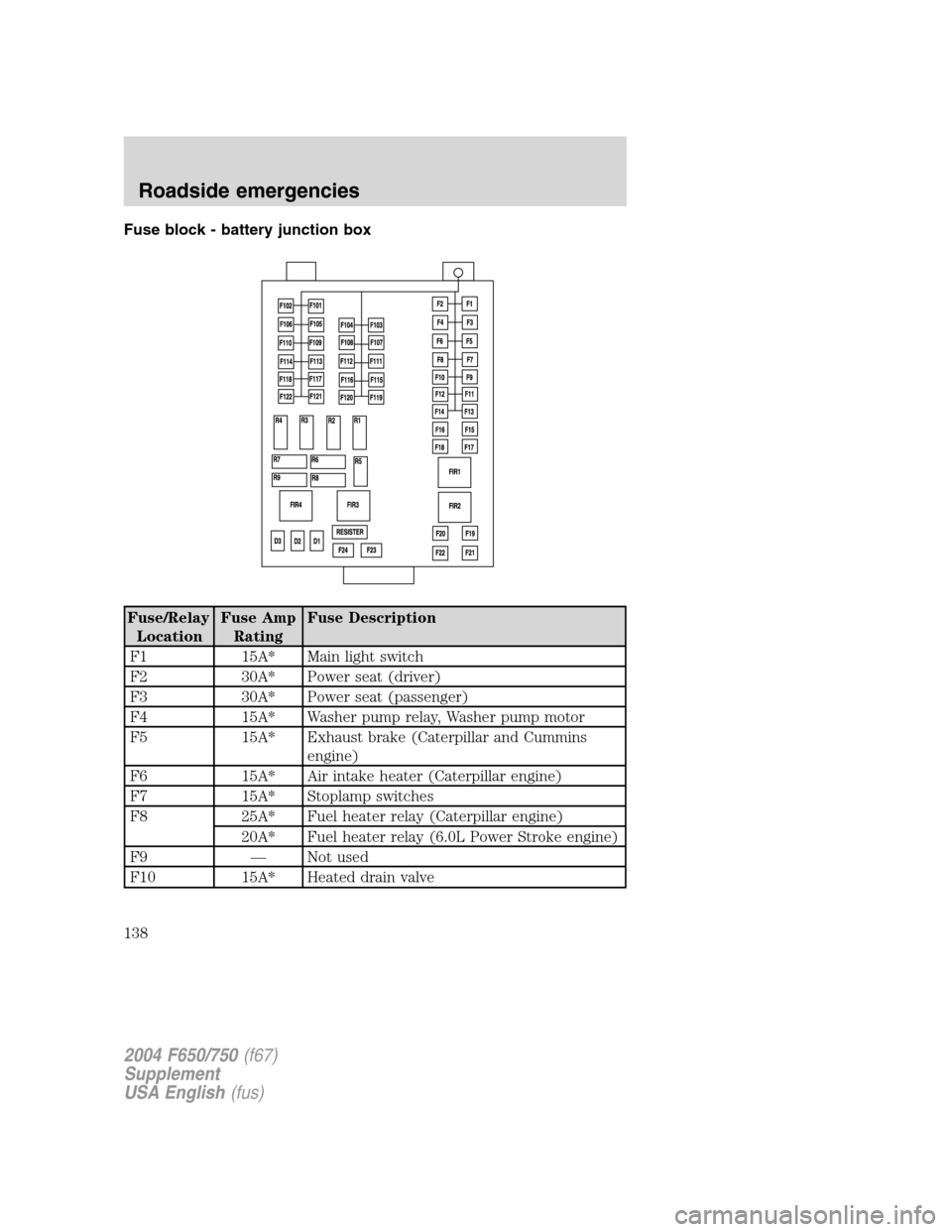
Fuse block - battery junction box
Fuse/Relay
LocationFuse Amp
RatingFuse Description
F1 15A* Main light switch
F2 30A* Power seat (driver)
F3 30A* Power seat (passenger)
F4 15A* Washer pump relay, Washer pump motor
F5 15A* Exhaust brake (Caterpillar and Cummins
engine)
F6 15A* Air intake heater (Caterpillar engine)
F7 15A* Stoplamp switches
F8 25A* Fuel heater relay (Caterpillar engine)
20A* Fuel heater relay (6.0L Power Stroke engine)
F9—Not used
F10 15A* Heated drain valve
2004 F650/750(f67)
Supplement
USA English(fus)
Roadside emergencies
138
Page 139 of 264
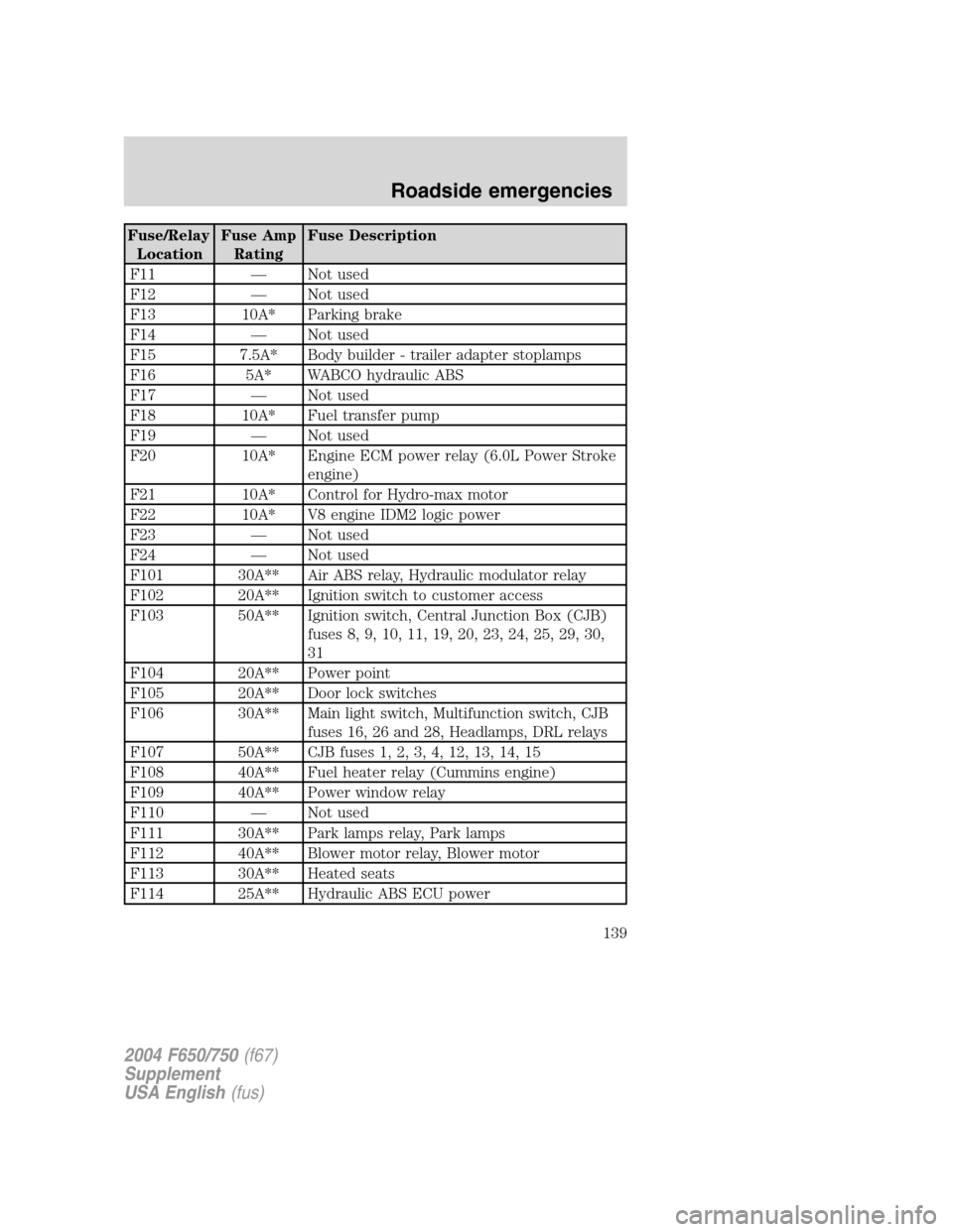
Fuse/Relay
LocationFuse Amp
RatingFuse Description
F11—Not used
F12—Not used
F13 10A* Parking brake
F14—Not used
F15 7.5A* Body builder - trailer adapter stoplamps
F16 5A* WABCO hydraulic ABS
F17—Not used
F18 10A* Fuel transfer pump
F19—Not used
F20 10A* Engine ECM power relay (6.0L Power Stroke
engine)
F21 10A* Control for Hydro-max motor
F22 10A* V8 engine IDM2 logic power
F23—Not used
F24—Not used
F101 30A** Air ABS relay, Hydraulic modulator relay
F102 20A** Ignition switch to customer access
F103 50A** Ignition switch, Central Junction Box (CJB)
fuses 8, 9, 10, 11, 19, 20, 23, 24, 25, 29, 30,
31
F104 20A** Power point
F105 20A** Door lock switches
F106 30A** Main light switch, Multifunction switch, CJB
fuses 16, 26 and 28, Headlamps, DRL relays
F107 50A** CJB fuses 1, 2, 3, 4, 12, 13, 14, 15
F108 40A** Fuel heater relay (Cummins engine)
F109 40A** Power window relay
F110—Not used
F111 30A** Park lamps relay, Park lamps
F112 40A** Blower motor relay, Blower motor
F113 30A** Heated seats
F114 25A** Hydraulic ABS ECU power
2004 F650/750(f67)
Supplement
USA English(fus)
Roadside emergencies
139
Page 140 of 264
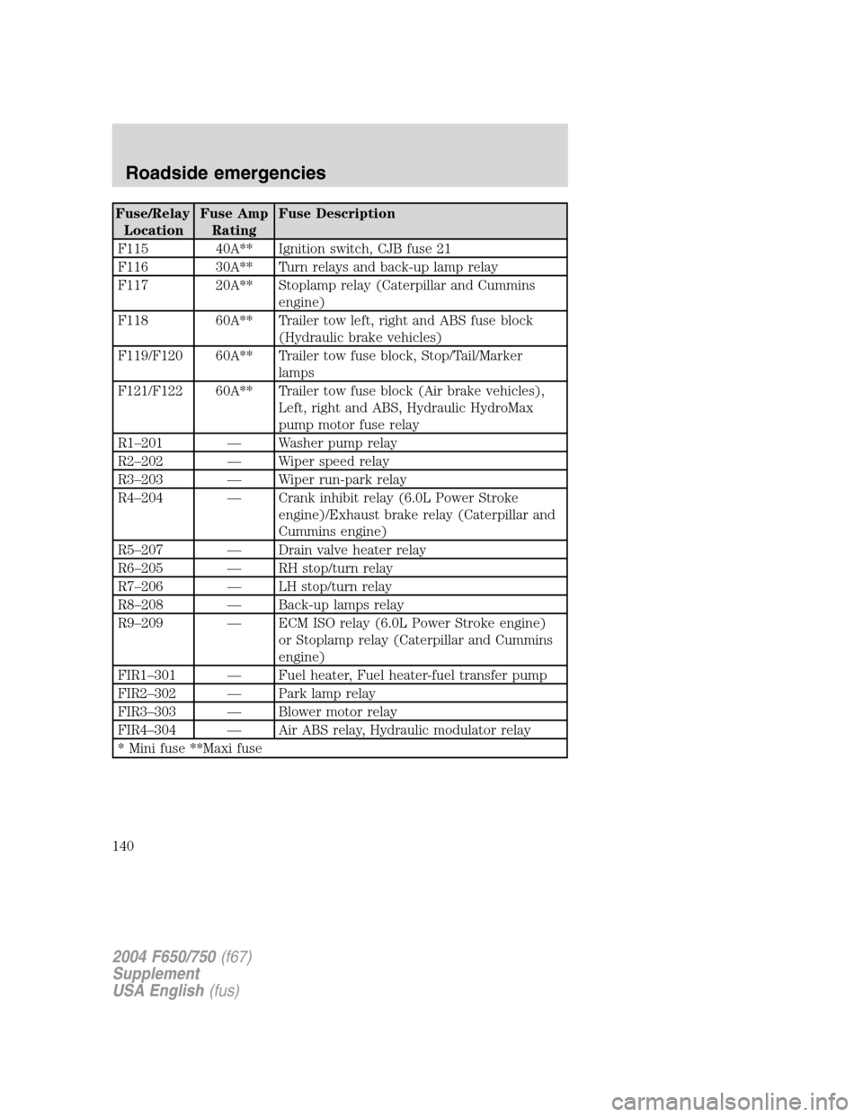
Fuse/Relay
LocationFuse Amp
RatingFuse Description
F115 40A** Ignition switch, CJB fuse 21
F116 30A** Turn relays and back-up lamp relay
F117 20A** Stoplamp relay (Caterpillar and Cummins
engine)
F118 60A** Trailer tow left, right and ABS fuse block
(Hydraulic brake vehicles)
F119/F120 60A** Trailer tow fuse block, Stop/Tail/Marker
lamps
F121/F122 60A** Trailer tow fuse block (Air brake vehicles),
Left, right and ABS, Hydraulic HydroMax
pump motor fuse relay
R1–201—Washer pump relay
R2–202—Wiper speed relay
R3–203—Wiper run-park relay
R4–204—Crank inhibit relay (6.0L Power Stroke
engine)/Exhaust brake relay (Caterpillar and
Cummins engine)
R5–207—Drain valve heater relay
R6–205—RH stop/turn relay
R7–206—LH stop/turn relay
R8–208—Back-up lamps relay
R9–209—ECM ISO relay (6.0L Power Stroke engine)
or Stoplamp relay (Caterpillar and Cummins
engine)
FIR1–301—Fuel heater, Fuel heater-fuel transfer pump
FIR2–302—Park lamp relay
FIR3–303—Blower motor relay
FIR4–304—Air ABS relay, Hydraulic modulator relay
* Mini fuse **Maxi fuse
2004 F650/750(f67)
Supplement
USA English(fus)
Roadside emergencies
140
Page 142 of 264
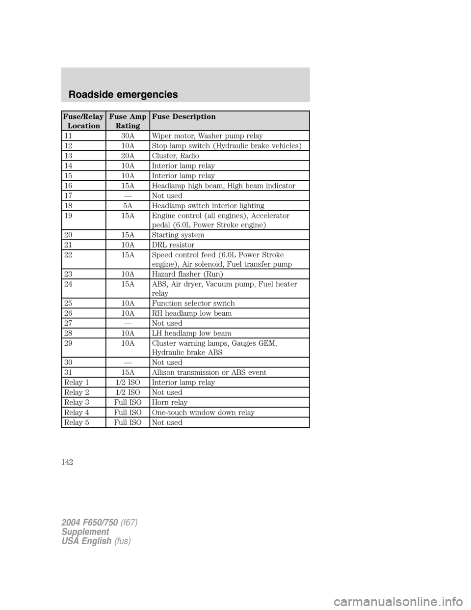
Fuse/Relay
LocationFuse Amp
RatingFuse Description
11 30A Wiper motor, Washer pump relay
12 10A Stop lamp switch (Hydraulic brake vehicles)
13 20A Cluster, Radio
14 10A Interior lamp relay
15 10A Interior lamp relay
16 15A Headlamp high beam, High beam indicator
17—Not used
18 5A Headlamp switch interior lighting
19 15A Engine control (all engines), Accelerator
pedal (6.0L Power Stroke engine)
20 15A Starting system
21 10A DRL resistor
22 15A Speed control feed (6.0L Power Stroke
engine), Air solenoid, Fuel transfer pump
23 10A Hazard flasher (Run)
24 15A ABS, Air dryer, Vacuum pump, Fuel heater
relay
25 10A Function selector switch
26 10A RH headlamp low beam
27—Not used
28 10A LH headlamp low beam
29 10A Cluster warning lamps, Gauges GEM,
Hydraulic brake ABS
30—Not used
31 15A Allison transmission or ABS event
Relay 1 1/2 ISO Interior lamp relay
Relay 2 1/2 ISO Not used
Relay 3 Full ISO Horn relay
Relay 4 Full ISO One-touch window down relay
Relay 5 Full ISO Not used
2004 F650/750(f67)
Supplement
USA English(fus)
Roadside emergencies
142
Page 215 of 264
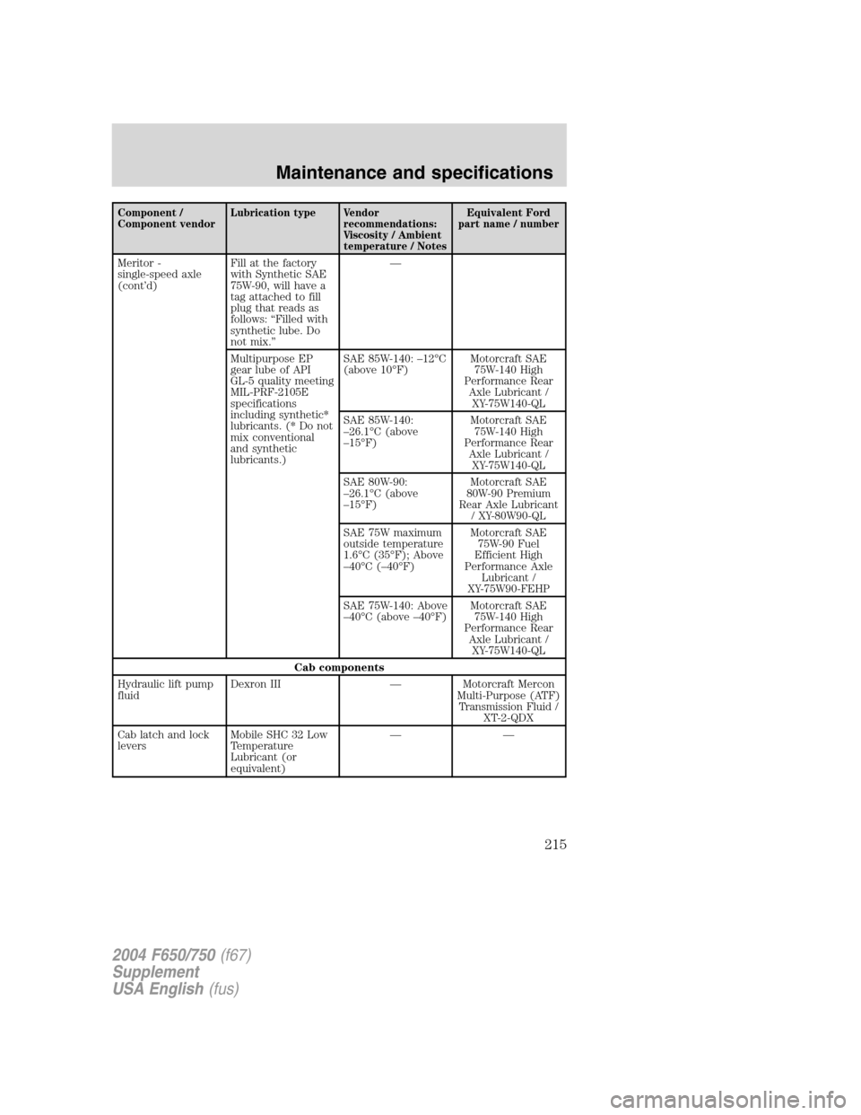
Component /
Component vendorLubrication type Vendor
recommendations:
Viscosity / Ambient
temperature / NotesEquivalent Ford
part name / number
Meritor -
single-speed axle
(cont’d)Fill at the factory
with Synthetic SAE
75W-90, will have a
tag attached to fill
plug that reads as
follows:“Filled with
synthetic lube. Do
not mix.”—
Multipurpose EP
gear lube of API
GL-5 quality meeting
MIL-PRF-2105E
specifications
including synthetic*
lubricants. (* Do not
mix conventional
and synthetic
lubricants.)SAE 85W-140:–12°C
(above 10°F)Motorcraft SAE
75W-140 High
Performance Rear
Axle Lubricant /
XY-75W140-QL
SAE 85W-140:
–26.1°C (above
–15°F)Motorcraft SAE
75W-140 High
Performance Rear
Axle Lubricant /
XY-75W140-QL
SAE 80W-90:
–26.1°C (above
–15°F)Motorcraft SAE
80W-90 Premium
Rear Axle Lubricant
/ XY-80W90-QL
SAE 75W maximum
outside temperature
1.6°C(35°F); Above
–40°C(–40°F)Motorcraft SAE
75W-90 Fuel
Efficient High
Performance Axle
Lubricant /
XY-75W90-FEHP
SAE 75W-140: Above
–40°C (above–40°F)Motorcraft SAE
75W-140 High
Performance Rear
Axle Lubricant /
XY-75W140-QL
Cab components
Hydraulic lift pump
fluidDexron III—Motorcraft Mercon
Multi-Purpose (ATF)
Transmission Fluid /
XT-2-QDX
Cab latch and lock
leversMobile SHC 32 Low
Temperature
Lubricant (or
equivalent)——
2004 F650/750(f67)
Supplement
USA English(fus)
Maintenance and specifications
215
Page 233 of 264
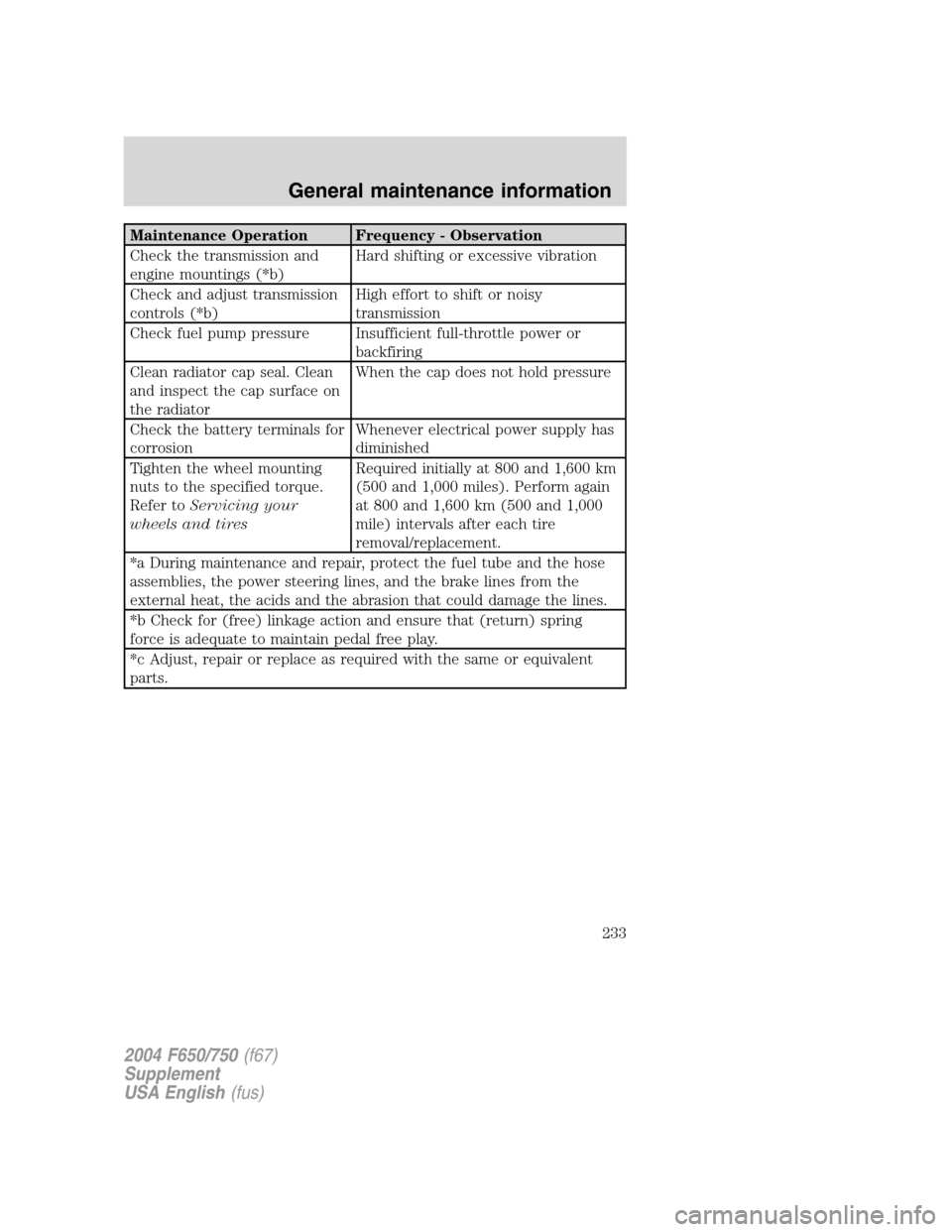
Maintenance Operation Frequency - Observation
Check the transmission and
engine mountings (*b)Hard shifting or excessive vibration
Check and adjust transmission
controls (*b)High effort to shift or noisy
transmission
Check fuel pump pressure Insufficient full-throttle power or
backfiring
Clean radiator cap seal. Clean
and inspect the cap surface on
the radiatorWhen the cap does not hold pressure
Check the battery terminals for
corrosionWhenever electrical power supply has
diminished
Tighten the wheel mounting
nuts to the specified torque.
Refer toServicing your
wheels and tiresRequired initially at 800 and 1,600 km
(500 and 1,000 miles). Perform again
at 800 and 1,600 km (500 and 1,000
mile) intervals after each tire
removal/replacement.
*a During maintenance and repair, protect the fuel tube and the hose
assemblies, the power steering lines, and the brake lines from the
external heat, the acids and the abrasion that could damage the lines.
*b Check for (free) linkage action and ensure that (return) spring
force is adequate to maintain pedal free play.
*c Adjust, repair or replace as required with the same or equivalent
parts.
2004 F650/750(f67)
Supplement
USA English(fus)
General maintenance information
233