clutch FORD F750 2010 12.G Owner's Manual
[x] Cancel search | Manufacturer: FORD, Model Year: 2010, Model line: F750, Model: FORD F750 2010 12.GPages: 274, PDF Size: 1.51 MB
Page 169 of 274
GENERAL SERVICING GUIDELINES AND PRECAUTIONS
As with any machine, care should be taken to avoid being injured when
performing maintenance, repairs or system checks. Improper or
incomplete service could result in the vehicle not working properly
which, in turn, may result in personal injury or damage to the vehicle or
equipment. It is the operator’s responsibility to see that the vehicle
receives proper care and maintenance. If you have any questions about
performing some service, have the service done by a qualified technician.
Servicing guidelines
When servicing your vehicle, always:
•turn off the ignition unless the particular procedure calls for the
engine to be running.
•set the parking brake or chock the wheels.
•use support stands, not a jack, whenever you must be under a raised
vehicle.
•do not smoke.
•wear safety glasses for eye protection.
•operate the engine in a well-ventilated area
•do not work on the brakes or the clutch unless the proper precautions
are taken to avoid inhaling friction material dust.
•do not wear loose-fitting clothing, hanging jewelry, watches or rings.
•avoid contact with hot metal parts. Allow the hot components to cool
before working with, or around them.
Quality service parts are available through your dealer. If dealer parts are
not used, the owner must make sure that the parts that are being used
are equivalent quality to dealer parts.
WARNING:The use of inferior parts can adversely affect the
quality and reliability of your vehicle which, in turn, can result in
property damage, personal injury or death.
Note:To avoid damage to the vehicle’s electrical components, disconnect
the positive (+) and negative (-) battery cables prior to electric welding.
Attach the welder ground cable as close as possible to the part being
welded. If it is necessary to weld close to an electrical component, it is
recommended that the electronic component be temporarily removed.
Follow the periodic lubrication procedures and regular inspection
intervals as outlined. Have your dealer or service center inspect your
Maintenance and Specifications
169
2010 F-650/750(f67)
Supplement(supplement), 1st Printing
USA(fus)
Page 184 of 274

Fan clutches
Your vehicle’s cooling system is equipped with a viscous fan clutch.
•The fan clutch helps control cooling, increase performance, improve
fuel economy and reduce noise.
•The fan clutch is controlled by bimetallic spring sensors. Do not
tamper with these sensors as this may change their calibration or keep
the fan clutch from operating at all.
WARNING:Stay clear of the fan/fan area while the engine is
running or possible personal injury may occur.
FUEL FILTER/WATER SEPARATOR
WARNING:Do not drain water separator while engine is
running. Fuel may ignite if separator is drained while engine is
running or vehicle is moving.
The fuel filter/water separator removes any contaminated particles
and/or water from the fuel before the fuel enters the engine.
Refer to your engine operator’s manual for information on draining and
replacing the fuel filter.
FUEL INFORMATION
Important safety precautions
WARNING:Do not overfill the fuel tank. The pressure in an
overfilled tank may cause leakage and lead to fuel spray and fire.
WARNING:The fuel system may be under pressure. If the fuel
cap is venting vapor or if you hear a hissing sound, wait until it
stops before completely removing the cap.
WARNING:Automotive fuels can cause serious injury or death
if misused or mishandled.
Maintenance and Specifications
184
2010 F-650/750(f67)
Supplement(supplement), 1st Printing
USA(fus)
Page 192 of 274
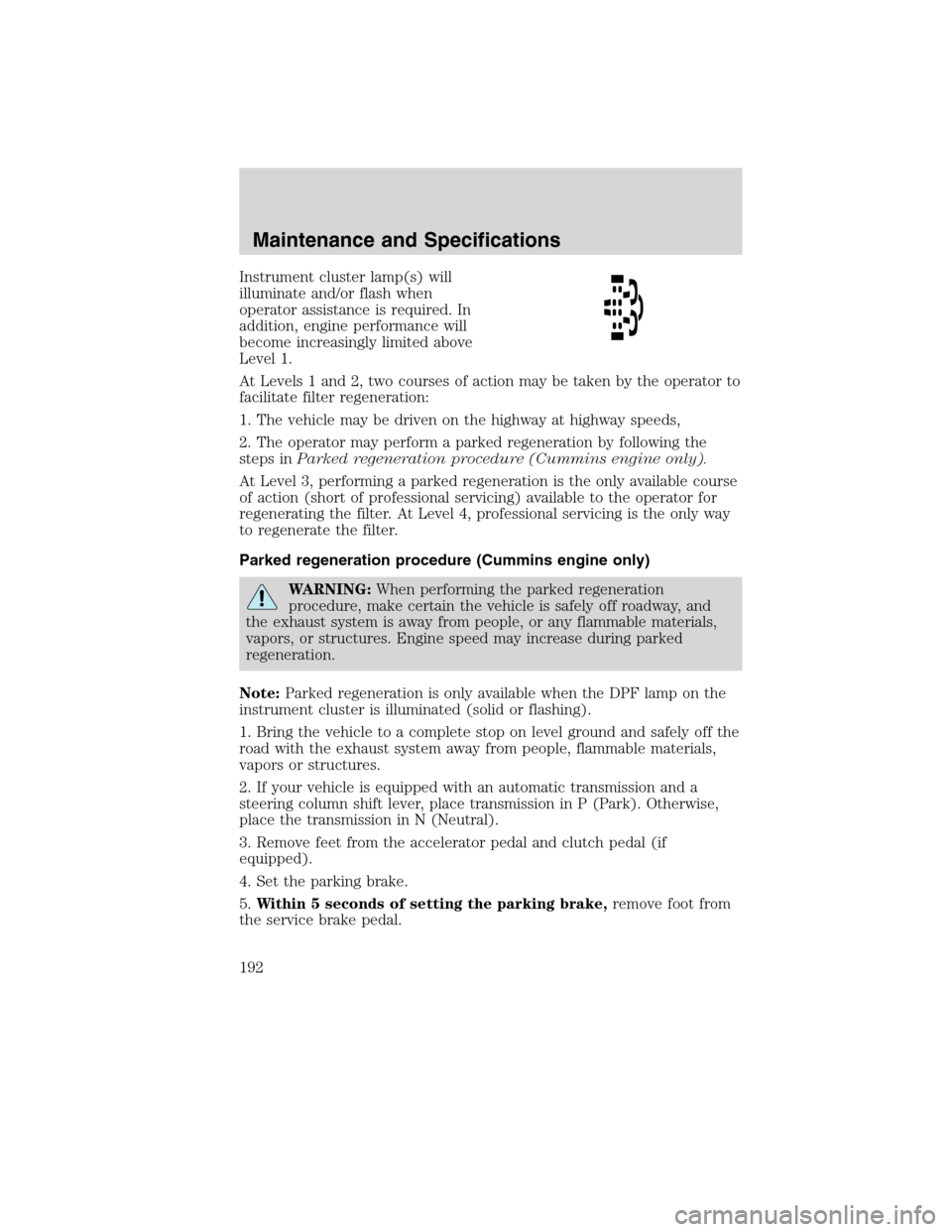
Instrument cluster lamp(s) will
illuminate and/or flash when
operator assistance is required. In
addition, engine performance will
become increasingly limited above
Level 1.
At Levels 1 and 2, two courses of action may be taken by the operator to
facilitate filter regeneration:
1. The vehicle may be driven on the highway at highway speeds,
2. The operator may perform a parked regeneration by following the
steps inParked regeneration procedure (Cummins engine only).
At Level 3, performing a parked regeneration is the only available course
of action (short of professional servicing) available to the operator for
regenerating the filter. At Level 4, professional servicing is the only way
to regenerate the filter.
Parked regeneration procedure (Cummins engine only)
WARNING:When performing the parked regeneration
procedure, make certain the vehicle is safely off roadway, and
the exhaust system is away from people, or any flammable materials,
vapors, or structures. Engine speed may increase during parked
regeneration.
Note:Parked regeneration is only available when the DPF lamp on the
instrument cluster is illuminated (solid or flashing).
1. Bring the vehicle to a complete stop on level ground and safely off the
road with the exhaust system away from people, flammable materials,
vapors or structures.
2. If your vehicle is equipped with an automatic transmission and a
steering column shift lever, place transmission in P (Park). Otherwise,
place the transmission in N (Neutral).
3. Remove feet from the accelerator pedal and clutch pedal (if
equipped).
4. Set the parking brake.
5.Within 5 seconds of setting the parking brake,remove foot from
the service brake pedal.
Maintenance and Specifications
192
2010 F-650/750(f67)
Supplement(supplement), 1st Printing
USA(fus)
Page 193 of 274
The engine speed may increase slightly. To allow parked regeneration to
continue uninterrupted:
1. The vehicle must remain parked
2. The transmission must remain in P (Park) or N (Neutral) (as
previously described in Step 2).
3. The accelerator pedal, service brake pedal, and clutch pedal (if
equipped) must not be pressed
4. The parking brake must remain set
On average (depending on filter level and other factors), the process will
take 20–30 minutes to complete. The DPF lamp will turn off when the
process is complete. Repeat Steps 1–5, if parked regeneration is interrupted.
To discontinue parked regeneration (Cummins engine only)
Press any of the floor pedals to discontinue parked regeneration.
Diesel particulate filter maintenance and service
The DPF is designed to retain a relatively large amount of residual ash
and provide many miles and hours of maintenance-free operation. At
some point, generally beyond 150,000 miles (240,000 km) or 5,000 hours
of operation (whichever comes first), the DPF will require professional
cleaning to remove the accumulated ash
The exact number of miles or hours of operation will vary greatly
depending upon vehicle/engine loading and operating conditions, ash
content of the engine oil, and quality of the diesel fuel used in your
truck. Adhering to your engine manufacturer’s recommended oil and fuel
specifications will maximize the miles and hours of operation before a
DPF professional cleaning is required. Refer to your engine
manufacturer’s owner’s manual for more details regarding recommended
maintenance and service of your DPF.
Exhaust outlet assembly
WARNING:The normal operating temperature of the exhaust
system is very high. Never work around or attempt to repair any
part of the exhaust system until it has cooled. Failure to follow these
instructions may result in serious personal injury.
The exhaust outlet assembly on your vehicle is a uniquely functioning
device that accompanies the DPF assembly. It is designed to help control
the temperature of the exhaust during the DPF regeneration process.Do
Maintenance and Specifications
193
2010 F-650/750(f67)
Supplement(supplement), 1st Printing
USA(fus)
Page 194 of 274

not modify or remove this device. Modification of the system
and/or additions of aftermarket devices can reduce the
effectiveness of the system, as well as cause damage to the
exhaust system and/or engine. Any modifications may also
invalidate the vehicle and/or engine warranties. See the vehicle
and engine warranty guides for more information.
The inlet holes in the side of the assembly are functional. These holes
allow outside air to be drawn into the outlet assembly. The holes need to
be kept clear of mud and other foreign material to maintain proper
functionality of the system. One way to keep the holes clear is to spray
the outlet assembly with a hose when washing the vehicle. Failure to
keep the functional holes clear of foreign material may result in the holes
becoming blocked or plugged.Blocked/plugged holes or
modification/removal of the outlet assembly could result in
elevated exhaust temperatures which may result in
vehicle/property damage and/or personal injury.
NOISE EMISSIONS – EXTERIOR
In order to comply with the federal exterior noise regulations, your
vehicle may be equipped with noise emission items. Depending on the
vehicle configuration, it may have all or some of the following items:
Air Intake System
•Air Cleaner:should be inspected and its location should not be
altered. Do not alter inlet and outlet piping.
Body
•Wheel Well:splash shields, cab shields and under-hood insulation
should be inspected for deterioration, dislocation, and orientation.
Cooling System
•Check the fan for damage to blades; replace, if damaged, with the
recommended parts. Inspect for fan to shroud interference, and any
damage to shroud such as cracks and holes.
•The fan ratio should not be changed and the fan spacer dimensions
and positions should not be altered.
•Inspect the fan clutch for proper operation, make sure that the fan is
disengaged when cooling of the engine is not required.
•Check for proper operation of radiator shutters, if equipped. The
shutters should be open during normal operating temperatures.
Maintenance and Specifications
194
2010 F-650/750(f67)
Supplement(supplement), 1st Printing
USA(fus)
Page 197 of 274

2. Visually inspect the fluid level; the level should be at the bottom of
the fill ports.
3. If necessary, add brake fluid from a clean unopened container until the
level reaches the bottom of the fill ports. Do not fill above this line.
4. Use only a DOT 3 brake fluid certified to meet manufacturer
specifications. Refer toLubricant specificationsin this chapter.
WARNING:Brake fluid is toxic. If brake fluid contacts the eyes,
flush eyes with running water for 15 minutes. Seek medical
attention if irritation persists. If taken internally, drink water and
induce vomiting. Seek medical attention immediately.
WARNING:If you use a brake fluid that is not DOT 3, you will
cause permanent damage to your brakes.
WARNING:Do not let the reservoir for the master cylinder run
dry. This may cause the brakes to fail.
CLUTCH FLUID/LINKAGE ADJUSTMENTS
Clutch fluid (if equipped)
Check the clutch fluid level. Refer to theScheduled Maintenance
Guidechapter for the service interval schedules.
During normal operation, the fluid level in the clutch reservoir should
remain constant. If the fluid level drops, maintain the fluid level at the
step in the reservoir.
Use only a DOT 3 brake fluid designed to meet manufacturer
specifications. Refer toLubricant specificationsin this chapter.
WARNING:Carefully read cautionary information on product
label. For MEDICAL EMERGENCY INFORMATION, contact a
physician or Poison Control Center immediately; on Ford-Motorcraft
products call: 1-800-959-3673 (FORD). Failure to follow these
instructions may result in personal injury.
Maintenance and Specifications
197
2010 F-650/750(f67)
Supplement(supplement), 1st Printing
USA(fus)
Page 198 of 274

1. Set the parking brake, shift into 1
(First) and turn the engine off.
2. Open the hood.
3. Clean the reservoir cap before
removal to prevent dirt and water
from entering the reservoir.
4. Remove cap and rubber
diaphragm from reservoir.
5. Add fluid until the level reaches
the step in the reservoir.
6. Reinstall rubber diaphragm and cap onto reservoir.
Clutch linkage (if equipped)
Lubricate the clutch linkage using the following procedure. Refer to the
Scheduled Maintenance Guidechapter for the service interval
schedules.
Use a grease which meets manufacturer specifications. Refer to
Lubricant specificationsin this chapter.
1. Set the parking brake, shift into 1 (First) and turn the engine off.
2. Remove the inspection cover from the clutch housing.
•Transmission and clutch
removed for clarity.
3. With a grease gun, lubricate the clutch release bearing (at one
location) and the clutch release shaft (at two locations) using the grease
fittings provided.
4. Lubricate clutch release wear pads at the two locations where they
contact the clutch release bearing using a brush or similar tool.
5. Install the inspection cover onto the clutch housing.
Maintenance and Specifications
198
2010 F-650/750(f67)
Supplement(supplement), 1st Printing
USA(fus)
Page 221 of 274

ComponentLubrication
typeViscosity /
Ambient
temperature /
NotesEquivalent
Ford part
name / number
Driveshaft
U-joint GC/LB NLGI #2
lithium
complex-based
moly grease or
multi-purpose
lithium complex
grease— Motorcraft
Premium Long
Life Grease /
XG-1-C
Clutch
Release bearing /
shafts / forkGC/LB NLGI #2
lithium
complex-based
moly grease or
multi-purpose
lithium complex
grease— Motorcraft
Premium Long
Life Grease /
XG-1-C
Reservoir DOT 3,
ESA-M6C25–A or
WSS-M6C62–A— Motorcraft High
Performance
DOT 3 Motor
Vehicle Brake
Fluid, PM-1 or
PM-1–C
Cooling system
Engine coolant Refer to engine operator’s manual
Maintenance and Specifications
221
2010 F-650/750(f67)
Supplement(supplement), 1st Printing
USA(fus)
Page 239 of 274

Among those acts presumed to constitute tampering are the following
acts listed:
Vehicle System Acts
Acoustical Shielding Removal of noise shields, hood
blanket, tunnel liner or acoustical
absorptive material.
Engine Removal or rendering inoperative
the engine speed governor so as to
allow engine speed to exceed
manufacturer specifications.
Removal of engine mounted noise
shield or oil pan enclosure.
Engine Air Induction System Removal of the air duct, silencer,
air cleaner, and/or air cleaner
element and baffle in air cleaner;
re-indexing of air cleaner.
Exhaust System Removal or rendering inoperative
exhaust system components
including the catalytic converter -
muffler assembly, inlet pipe, outlet
pipe, resonator and flexpipe.
Rotation of horizontal exhaust
system directional outlet pipe to
cause the exhaust to be emitted in
a direction other than the
orientation the vehicle was
originally produced with.
Engine Cooling System Removal or rendering inoperative
the fan clutch. Removal or
modification of the fan shroud.
Replacing a fixed fan with a fan of
increased diameter, different
number of blades or different pitch
width.
Scheduled Maintenance Guide
239
2010 F-650/750(f67)
Supplement(supplement), 1st Printing
USA(fus)
Page 244 of 274

Check every oil change
Engine systemCheck the engine cooling system -
hoses, clamps and protection*.
Inspect the drive belts.
Exhaust systemInspect the entire exhaust system
(including the inlet pipe(s),
muffler(s), outlet pipe(s), clamps and
fasteners) for holes, leakage,
breakage, corrosive damage and
separation from other components.
Adjust, service or replace with the
same or the equivalent part. (Also a
noise emission control service).
Suspension systemTighten the front and rear spring
U-bolts to the specified torque.
Driveline and rear axle
systemLubricate the U-joints and the slip
yoke.
Brake systemLube the air brake foot control valve,
hinge and roller.
Inspect the drum brake linings
through the inspection holes.
Lubricate rear caliper slide rails.
Lubricate the brake camshafts (air
brakes only).
Lubricate the brake slack adjuster (air
brakes only).
Inspect the disc brake pads and the
piston boots (hydraulic brakes only).
Clutch systemLubricate the clutch release cross
shaft and all linkages.
Check the clutch fluid.
Fuel systemDrain the accumulated water or
sediment from the fuel tank(s).
Scheduled Maintenance Guide
244
2010 F-650/750(f67)
Supplement(supplement), 1st Printing
USA(fus)