differential FORD F750 2011 12.G Owners Manual
[x] Cancel search | Manufacturer: FORD, Model Year: 2011, Model line: F750, Model: FORD F750 2011 12.GPages: 290, PDF Size: 1.96 MB
Page 30 of 290
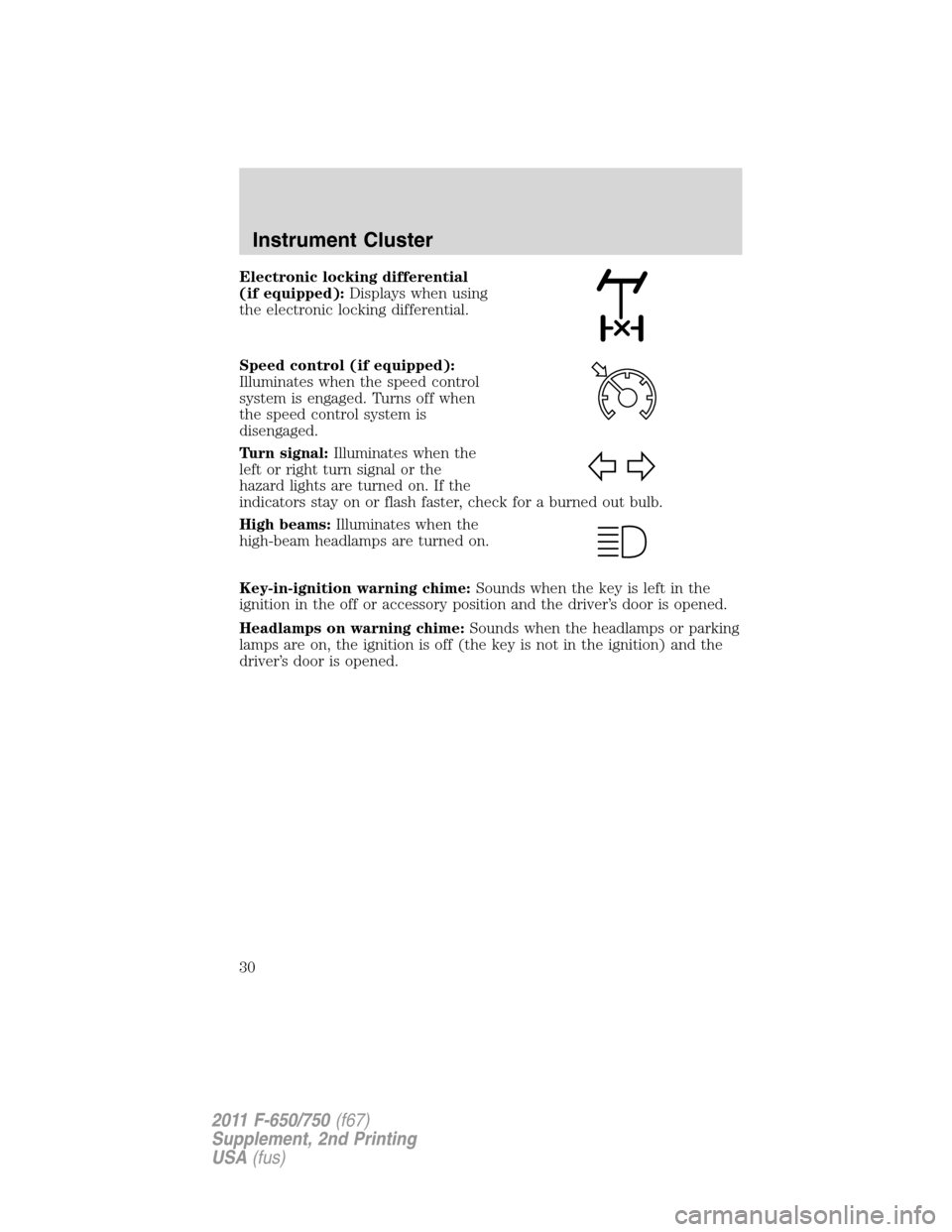
Electronic locking differential
(if equipped):Displays when using
the electronic locking differential.
Speed control (if equipped):
Illuminates when the speed control
system is engaged. Turns off when
the speed control system is
disengaged.
Turn signal:Illuminates when the
left or right turn signal or the
hazard lights are turned on. If the
indicators stay on or flash faster, check for a burned out bulb.
High beams:Illuminates when the
high-beam headlamps are turned on.
Key-in-ignition warning chime:Sounds when the key is left in the
ignition in the off or accessory position and the driver’s door is opened.
Headlamps on warning chime:Sounds when the headlamps or parking
lamps are on, the ignition is off (the key is not in the ignition) and the
driver’s door is opened.
Instrument Cluster
30
2011 F-650/750(f67)
Supplement, 2nd Printing
USA(fus)
Page 143 of 290
REAR AXLE INFORMATION
Axle operating temperature normally will not exceed 100°F (38°C). If
the operating temperature exceeds 230°F (110°C), the rate of axle
lubrication oxidation will increase and shorten the life of the lubricant
and seals, requiring axle lubrication changes to become more frequent to
preserve the axle. Extreme Pressure (EP) lubricants should not be run
consistently above 230°F (110°C).
Gross axle weight
Your truck has gross axle weight, gross vehicle weight and gross
combination weight ratings. Do not exceed these ratings.
WARNING:Exceeding these ratings by overloading can cause
component failure resulting in property damage, personal injury
or death.
Rear axles with locking or limited-slip differentials (if equipped)
If your vehicle is equipped with a locking or limited-slip differential, note
the following:
•Power will be transmitted to the opposite wheel should one of the
wheels begin to slip.
•Both wheels must be raised off the ground should it be necessary to
operate one wheel with the vehicle stationary.
WARNING:If both wheels are not raised off the ground, the
one wheel that is not raised may pull the vehicle off its support,
possibly resulting in personal injury
Driver-controlled differential lock
To prevent the vehicle from moving when servicing the wheels, tires or
brakes, turn the engine off and raise all drive wheels of the locker
differential axle. Axles equipped with NoSPIN Detroit Locker differentials
deliver power to both wheels even when only one wheel is on the
ground.
WARNING:Failure to raise all drive wheels with this type of
differential could cause the vehicle to move unexpectedly,
resulting in property damage, personal injury or death.
Driving
143
2011 F-650/750(f67)
Supplement, 2nd Printing
USA(fus)
Page 144 of 290
Care should be taken to avoid sudden accelerations when both drive
wheels are on a slippery surface.
WARNING:Sudden accelerations on slippery surfaces could
cause the wheels to spin, the vehicle to turn sideways on a
crowned road surface or in a turn, possibly resulting in loss of vehicle
control and personal injury.
Some drive axles have a driver-controlled differential lock. The
differential lock can lock or unlock the differential when the vehicle is
moving or stopped. When extra traction is required, the differential lock
will provide full power to both axles.
When the differential is locked, the vehicle’s turning radius will increase
(vehicle will “under-steer”)
The differential can be locked or unlocked when the vehicle is moving at
a constant speed of less than 25 mph (40 km/h) and while the wheels
are not slipping. The differential must not be locked when the vehicle is
traveling down steep grades and traction is minimal.
Note:Never use the differential lock at vehicle speeds above 25 mph
(40 km/h).
The differential lock and differential lock light will automatically
disengage at speeds above 25 mph (40 km/h). The differential lock will
remain off until either the vehicle is restarted or the differential lock
switch is turned off then back on.
Axle conversions
It is not recommended, or approved, for axle conversions to be
performed. However, it is understood that, on occasion, aftermarket
add-on axles are installed by others on the truck chassis which allow
operator control for weight transfer from other axles (i.e., air lift axles).
WARNING:When operating a loaded vehicle, the driver must
keep all adjustable axles on the ground at all times, supporting
their share of the vehicle’s load. Failure to do so can overload other
axles, tires, wheels, springs, steering components, brakes and frames,
resulting in early component failure, loss of vehicle control, possible
property damage and personal injury.
Driving
144
2011 F-650/750(f67)
Supplement, 2nd Printing
USA(fus)
Page 155 of 290
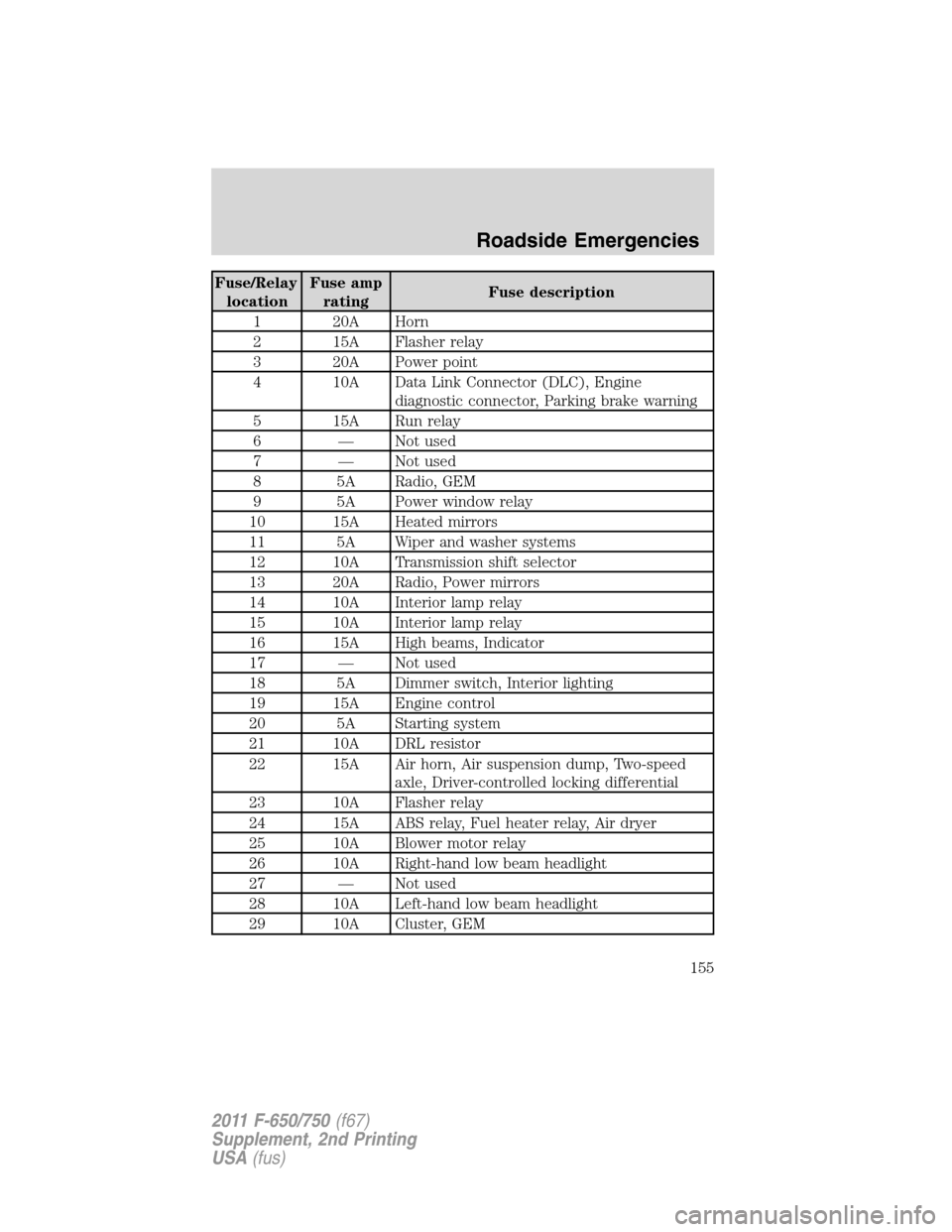
Fuse/Relay
locationFuse amp
ratingFuse description
1 20A Horn
2 15A Flasher relay
3 20A Power point
4 10A Data Link Connector (DLC), Engine
diagnostic connector, Parking brake warning
5 15A Run relay
6 — Not used
7 — Not used
8 5A Radio, GEM
9 5A Power window relay
10 15A Heated mirrors
11 5A Wiper and washer systems
12 10A Transmission shift selector
13 20A Radio, Power mirrors
14 10A Interior lamp relay
15 10A Interior lamp relay
16 15A High beams, Indicator
17 — Not used
18 5A Dimmer switch, Interior lighting
19 15A Engine control
20 5A Starting system
21 10A DRL resistor
22 15A Air horn, Air suspension dump, Two-speed
axle, Driver-controlled locking differential
23 10A Flasher relay
24 15A ABS relay, Fuel heater relay, Air dryer
25 10A Blower motor relay
26 10A Right-hand low beam headlight
27 — Not used
28 10A Left-hand low beam headlight
29 10A Cluster, GEM
Roadside Emergencies
155
2011 F-650/750(f67)
Supplement, 2nd Printing
USA(fus)
Page 160 of 290
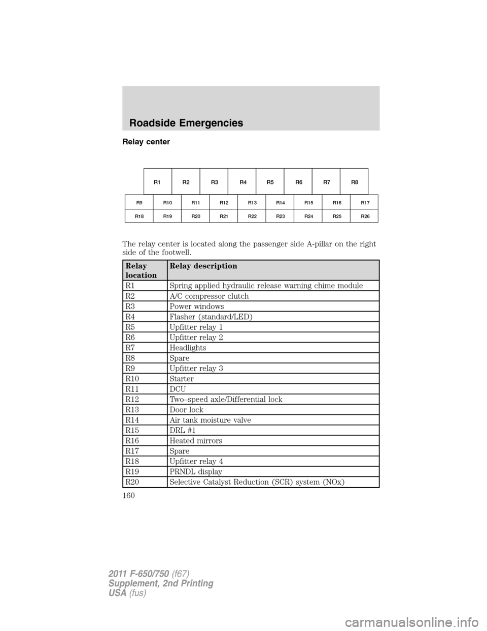
Relay center
The relay center is located along the passenger side A-pillar on the right
side of the footwell.
Relay
locationRelay description
R1 Spring applied hydraulic release warning chime module
R2 A/C compressor clutch
R3 Power windows
R4 Flasher (standard/LED)
R5 Upfitter relay 1
R6 Upfitter relay 2
R7 Headlights
R8 Spare
R9 Upfitter relay 3
R10 Starter
R11 DCU
R12 Two–speed axle/Differential lock
R13 Door lock
R14 Air tank moisture valve
R15 DRL #1
R16 Heated mirrors
R17 Spare
R18 Upfitter relay 4
R19 PRNDL display
R20 Selective Catalyst Reduction (SCR) system (NOx)
R1
R9 R10 R11 R12 R13 R14 R15 R16 R17
R18 R19 R20 R21 R22 R23 R24 R25 R26
R2 R3 R4 R5 R6 R7 R8
Roadside Emergencies
160
2011 F-650/750(f67)
Supplement, 2nd Printing
USA(fus)
Page 167 of 290
WARNING:To reduce the risk of personal injury or property
damage when manually releasing the spring brakes, be sure to
block the wheels so the vehicle cannot move once the brakes are
released.
Towing the vehicle with the front wheels suspended
When it is necessary to tow a vehicle with the front wheels suspended,
extra precautions must be taken to avoid transmission or differential
damage. Proceed as follows:
•Remove the axle shafts from the axle assembly to prevent the wheels
from driving the differential and the transmission.
•The wheel hub ends must be covered to prevent loss of axle lubricant
and entrance of other contaminants. If the axle shafts are not
removed, removal of the driveshaft is required.
Note:To avoid transmission damage, vehicles should not be towed even
a short distance without suspending rear wheels or removing the axle
shafts or driveshaft.
Note:In the event the chassis is equipped with a tandem axle and the
vehicle is to be towed from the front, the forward rear axle may be
raised to clear the road surface and secured to the frame by chains or
U-bolts, allowing only the rear rear axle to contact the road surface. Axle
shafts must be removed from the rear rear axle assembly. The wheel hub
ends must be covered to prevent loss of axle lubricant and entrance of
contaminants. Use extreme care in securing the chains or U-bolts to
avoid possible damage to the brake lines, hoses or other components.
Towing vehicles equipped with a driver-controlled differential lock
Note:If the vehicle must be towed to a service facility with the drive
axle wheels on the ground, it is necessary to remove the axle shafts
before the vehicle is towed.
Roadside Emergencies
167
2011 F-650/750(f67)
Supplement, 2nd Printing
USA(fus)
Page 168 of 290
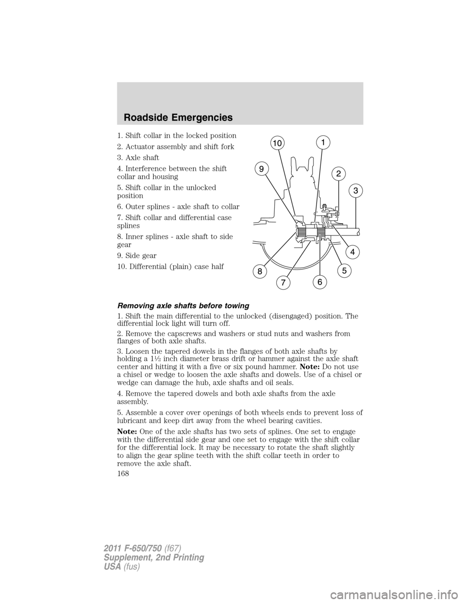
1. Shift collar in the locked position
2. Actuator assembly and shift fork
3. Axle shaft
4. Interference between the shift
collar and housing
5. Shift collar in the unlocked
position
6. Outer splines - axle shaft to collar
7. Shift collar and differential case
splines
8. Inner splines - axle shaft to side
gear
9. Side gear
10. Differential (plain) case half
Removing axle shafts before towing
1. Shift the main differential to the unlocked (disengaged) position. The
differential lock light will turn off.
2. Remove the capscrews and washers or stud nuts and washers from
flanges of both axle shafts.
3. Loosen the tapered dowels in the flanges of both axle shafts by
holding a 1
1�2inch diameter brass drift or hammer against the axle shaft
center and hitting it with a five or six pound hammer.Note:Do not use
a chisel or wedge to loosen the axle shafts and dowels. Use of a chisel or
wedge can damage the hub, axle shafts and oil seals.
4. Remove the tapered dowels and both axle shafts from the axle
assembly.
5. Assemble a cover over openings of both wheels ends to prevent loss of
lubricant and keep dirt away from the wheel bearing cavities.
Note:One of the axle shafts has two sets of splines. One set to engage
with the differential side gear and one set to engage with the shift collar
for the differential lock. It may be necessary to rotate the shaft slightly
to align the gear spline teeth with the shift collar teeth in order to
remove the axle shaft.
Roadside Emergencies
168
2011 F-650/750(f67)
Supplement, 2nd Printing
USA(fus)
Page 169 of 290
Installing the axle shafts
1. Remove the covers from the wheel ends.
2. Shift the differential lock to the unlocked (disengaged) position.
3. Install the axle shafts.
•Place the gaskets on the wheel hub studs.
•Push the right-hand axle shaft and gasket into the wheel end and
housing until the shaft stops against the differential shift collar.
•Push down and in on the axle shaft flange and rotate the shaft until
the splines of the shaft and shift collar are engaged.
•Push the axle shaft further into the housing until the shaft stops
against the differential side gear.
•Push down on the axle shaft flange and rotate the shaft until the
splines of the shaft and side gear are engaged.
•Push the axle shaft completely into the housing until the axle shaft
flange and the gasket are flush against the wheel hub.
•Install the left-hand axle shaft and gasket into the wheel end.
4. If tapered dowels are required, install them at each stud and into the
flange of the axle shaft. Use a punch or drift and hammer, if needed.
5. Install the fasteners and tighten to correct torque value. Refer to the
Service Manual.
Towing the vehicle with the rear wheels suspended
Note:To avoid damage to the cab roof or air deflector when towing the
vehicle backward (rear wheels suspended) the air deflector must be
removed.
Whenever possible, it is preferable to tow a disabled vehicle from the
rear by raising the rear of the chassis. When towing a vehicle with the
rear of the chassis suspended, the front wheels must be locked in the
straight-ahead position.
Vehicles equipped with a manual transmission must have at least 1.0 pint
(0.5L) of transmission fluid drained from the case. This will prevent the
transmission fluid from entering the clutch housing and fluid saturating
the clutch discs. Make sure that the transmission fluid is replaced before
the vehicle is returned to service.
Roadside Emergencies
169
2011 F-650/750(f67)
Supplement, 2nd Printing
USA(fus)
Page 184 of 290
Check to make sure that the axle mounting U-bolt nuts, attaching or
mounting bolts and nuts are securely tightened. Regularly check front
axle for damage, binding, worn parts and adequate lubrication.
At regular intervals, or during other scheduled maintenance, (tire
rotation/service, wheel bearing service, alignment, etc.) the kingpins
should be checked for excessive wear. Refer to the service manual for
proper procedures.
Toe-in setting - general inspection
Inspecting steer axle tires in the first 3,000–10,000 service miles
(5,000–16,000 service km) will generally show if tires are wearing
normally.
Rapid outside shoulder wear on both tires indicates too much toe-in.
Rapid inside shoulder wear on both tires indicates too much toe-out. In
P&D-type service, left-to-right steer tire tread life differentials up to 40%
can be observed depending on routes and other variables.
Follow the tire manufacturer’s recommended cold inflation pressure for
the tire size, load range (ply rating) and steer axle loading typical for
their operation (each steer axle tire will equal
1�2steer axle loading).
Special applications may warrant a setting based on past experience with
the type of tire operating loads and conditions. Radial tires are more
sensitive to toe-in setting than bias ply tires. While not insensitive to
vehicle alignment, fine tuning school bus alignment to line-haul truck
standards will not drastically improve tire tread life.
It is essential that correct toe-in and tire pressure be maintained for
optimum tire wear.
Rear axle - general inspection
Check to make sure that the axle mounting U-bolts, attaching or
mounting bolts and nuts are securely tightened. Refer toU-bolt nut
torquein this chapter. Regularly check the rear axle for damaged,
binding or worn parts.
NoSpin Detroit Locker positive locking differential
Vehicles equipped with this type differential have the operator’s manual
supplied with the vehicle. Refer to this manual for maintenance checks.
Maintenance and Specifications
184
2011 F-650/750(f67)
Supplement, 2nd Printing
USA(fus)
Page 250 of 290
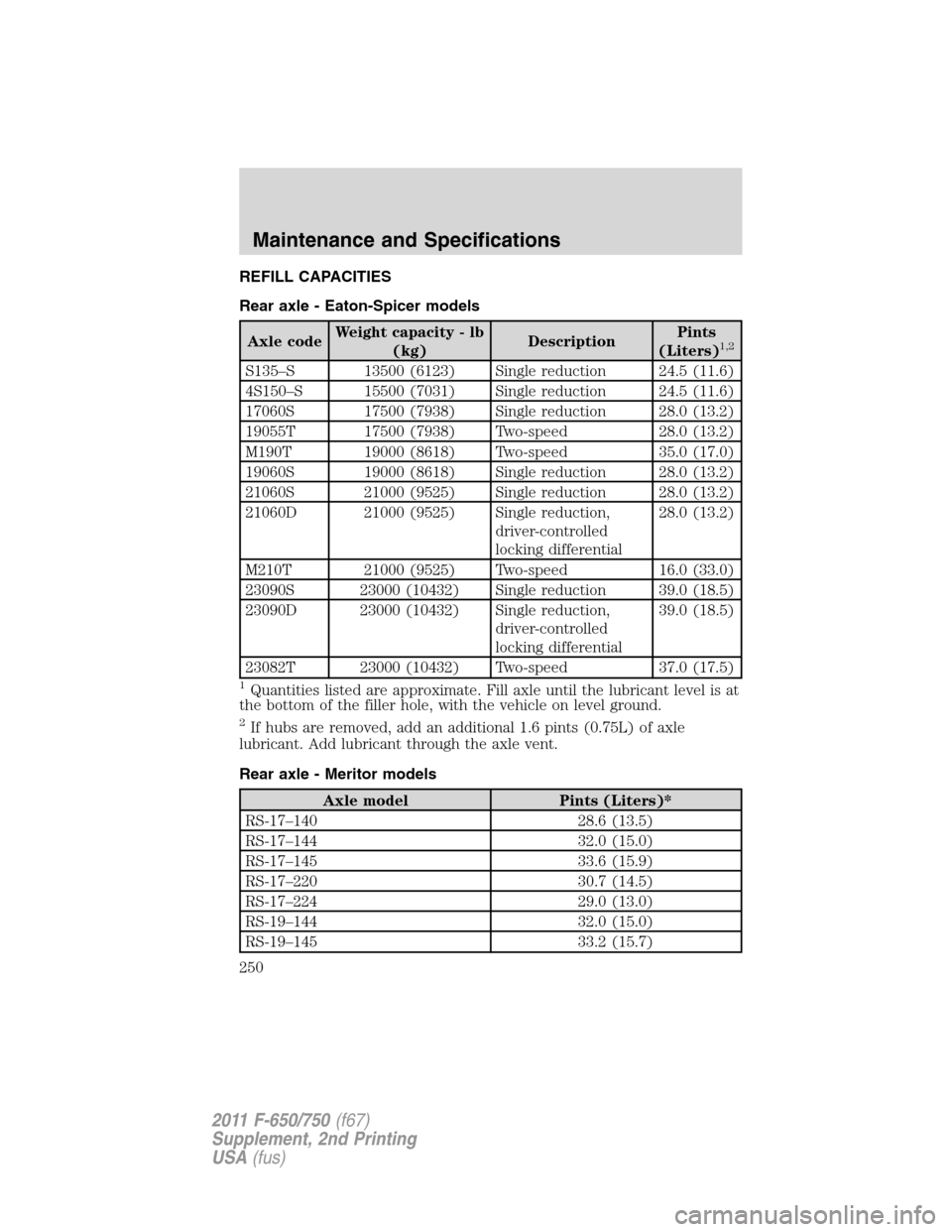
REFILL CAPACITIES
Rear axle - Eaton-Spicer models
Axle codeWeight capacity - lb
(kg)DescriptionPints
(Liters)1,2
S135–S 13500 (6123) Single reduction 24.5 (11.6)
4S150–S 15500 (7031) Single reduction 24.5 (11.6)
17060S 17500 (7938) Single reduction 28.0 (13.2)
19055T 17500 (7938) Two-speed 28.0 (13.2)
M190T 19000 (8618) Two-speed 35.0 (17.0)
19060S 19000 (8618) Single reduction 28.0 (13.2)
21060S 21000 (9525) Single reduction 28.0 (13.2)
21060D 21000 (9525) Single reduction,
driver-controlled
locking differential28.0 (13.2)
M210T 21000 (9525) Two-speed 16.0 (33.0)
23090S 23000 (10432) Single reduction 39.0 (18.5)
23090D 23000 (10432) Single reduction,
driver-controlled
locking differential39.0 (18.5)
23082T 23000 (10432) Two-speed 37.0 (17.5)
1Quantities listed are approximate. Fill axle until the lubricant level is at
the bottom of the filler hole, with the vehicle on level ground.
2If hubs are removed, add an additional 1.6 pints (0.75L) of axle
lubricant. Add lubricant through the axle vent.
Rear axle - Meritor models
Axle model Pints (Liters)*
RS-17–140 28.6 (13.5)
RS-17–144 32.0 (15.0)
RS-17–145 33.6 (15.9)
RS-17–220 30.7 (14.5)
RS-17–224 29.0 (13.0)
RS-19–144 32.0 (15.0)
RS-19–145 33.2 (15.7)
Maintenance and Specifications
250
2011 F-650/750(f67)
Supplement, 2nd Printing
USA(fus)