oil FORD F750 2011 12.G Owners Manual
[x] Cancel search | Manufacturer: FORD, Model Year: 2011, Model line: F750, Model: FORD F750 2011 12.GPages: 290, PDF Size: 1.96 MB
Page 2 of 290
Seating and Safety Restraints 69
Seating 69
Safety restraints 80
Child restraints 88
Driving 104
Starting 104
Brakes 111
Air suspension 132
Transmission operation 134
Vehicle loading 147
Roadside Emergencies 153
Hazard flasher switch 154
Fuses and relays 154
Jump starting 162
Wrecker towing 166
Customer Assistance 170
Getting assistance outside the U.S. and Canada 172
Reporting safety defects (U.S. only) 174
Reporting safety defects (Canada only) 174
Cleaning 175
Underbody preservation 181
Maintenance and Specifications 182
Hood 190
Engine oil 193
Battery 193
Engine coolant 196
Fuel information 197
Diesel Exhaust Fluid (DEF) 201
Wheel lug nut torque 229
Tire information 229
Lubricant specifications 237
Refill capacities 250
Table of Contents
2
2011 F-650/750(f67)
Supplement, 2nd Printing
USA(fus)
Page 9 of 290
ENTERING, EXITING AND/OR CLIMBING ON THIS VEHICLE
You must be careful and deliberate to minimize the possibility of personal
injury from a slip and fall when entering, exiting and/or climbing on this
vehicle. Always use the steps and assist handles before climbing. Do not
skip any steps or assist handles. Use three point contact at all times with
at least two feet and one hand or two hands and one foot firmly placed
during all phases of entering, exiting and/or climbing. Always keep your
shoe soles and hands clean. Keep the steps and assist handles free of
snow, ice, oil, grease, substances or debris. Be sure to use extra care in
bad weather. Avoid wearing thick gloves. Always perform trailer hook-up
while standing on the ground.
WARNING:Do not carry items while entering, exiting, and/or
climbing. Make sure you keep a firm grip. Always FACE the
VEHICLE STEP and HANDLE SYSTEM while climbing up and down.
Do not climb behind the cab unless you have three point contact with
a step and handle system at all times.
Introduction
9
2011 F-650/750(f67)
Supplement, 2nd Printing
USA(fus)
Page 11 of 290
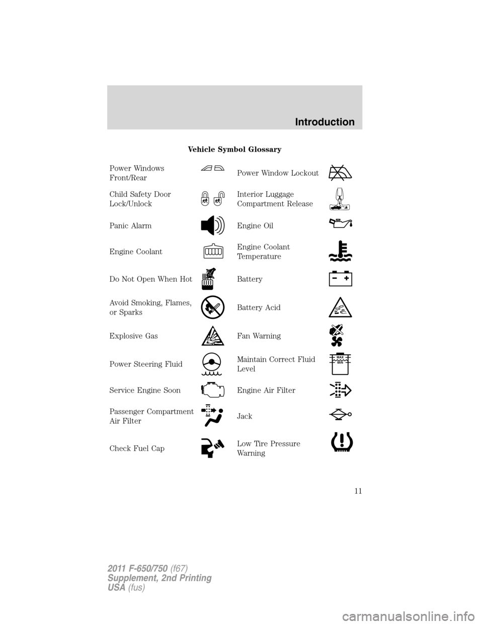
Vehicle Symbol Glossary
Power Windows
Front/Rear
Power Window Lockout
Child Safety Door
Lock/UnlockInterior Luggage
Compartment Release
Panic AlarmEngine Oil
Engine CoolantEngine Coolant
Temperature
Do Not Open When HotBattery
Avoid Smoking, Flames,
or SparksBattery Acid
Explosive GasFan Warning
Power Steering FluidMaintain Correct Fluid
LevelMAX
MIN
Service Engine SoonEngine Air Filter
Passenger Compartment
Air FilterJack
Check Fuel CapLow Tire Pressure
Warning
Introduction
11
2011 F-650/750(f67)
Supplement, 2nd Printing
USA(fus)
Page 12 of 290
To be sure your vehicle is ready to operate, conduct a pre-trip inspection
at the beginning of each work period. Follow the steps listed in this
section to ensure a proper vehicle inspection procedure. The pages in
this section may be produced locally and used on a regular basis.
VEHICLE INSPECTION INFORMATION
Note:Always make sure the parking brake is applied before starting the
engine.
Engine compartment (with engine stopped)
Engine oil level:Use the engine oil dipstick to verify that the
engine oil level is between the ADD and
OPERATING RANGE marks.
Engine coolant
level:Look through the plastic reservoir or the clear
sight glass on the reservoir, depending upon
vehicle equipment, and make sure the fluid is
within the minimum and maximum fluid level
range as marked on the reservoir.Do not
remove pressure cap until the coolant has
cooled.
Power steering fluid:Verify that the fluid level is in the proper
operating range. Refer toPower steering
fluidin theMaintenance and Specifications
chapter.
Brake fluid (master
cylinder):Remove the master cylinder caps and inspect
the fluid level. The full mark is at the bottom
of the opening of the fluid ports.
Hydraulic clutch
fluid:Check for adequate amount of hydraulic clutch
fluid. Fluid level should be at the step of the
reservoir; refer toClutch fluid/linkage
adjustmentsin theMaintenance and
Specificationschapter.
Belts (Fan,
alternator, water
pump and A/C
compressor):Check for glazing, fraying or cracking. There
should be no more than five-seven cracks per
rib, per inch (2.5 cm).
Vehicle Inspection Guide
12
2011 F-650/750(f67)
Supplement, 2nd Printing
USA(fus)
Page 14 of 290
Engine starting (parking brake applied)
Safety/Emergency
equipment:Prior to entering the cab, verify that the
vehicle is equipped with spare electrical fuses
(if used), three red reflective triangles, a
properly charged and rated fire extinguisher
and wheel chocks. Walk around the vehicle
and check that all steps and grab handles,
inside and out as well as behind, are tight and
clean. Use extreme caution and a three-point
stance at all times. Check door latches for
positive closing, latching and locking.
Starting the engine:Verify the parking brake is set. Press the
clutch (if equipped with a manual
transmission) and verify the transmission is in
neutral. Vehicles equipped with an automatic
transmission should be in N (Neutral) or P
(Park) if equipped with a park position.
Turn the key to the on position. When the
indicator light in the instrument cluster turns
off, turn the key to start.
Oil pressure builds:Make sure engine oil pressure is building to
normal operating range.
Air chime sounds (if
equipped with air
compressor):The low air pressure warning chime should
sound immediately after the engine starts but
before the compressor has built up pressure.
The low air pressure warning chime should
stop when the air pressure reaches 70 psi
(483 kPa) (or more). Let the air pressure
build to governed cut-out pressure, which
should occur between 115–130 psi
(793–896 kPa).
Vehicle Inspection Guide
14
2011 F-650/750(f67)
Supplement, 2nd Printing
USA(fus)
Page 18 of 290
Front brakes
Hoses:Check for cracked, worn or frayed hoses. Make
sure all couplings are secured.
Chambers:Make sure brake chambers are not cracked or
dented and that they are securely mounted.
Slack adjusters:Check for broken, loose or missing parts. The
angle between the push rod and adjuster arm
should be approximately 90° when the brakes
are applied. When pulled by hand, the push
rod should not move more than approximately
one inch (2.5 cm).
Drums:Make sure there are no cracks, dents or holes
and no loose or missing bolts. Make sure brake
linings are not worn, dangerously thin or
contaminated by lubricant.
Front wheels
Rims:Check for damaged or bent rims. Rims should
not have welding repairs and no rust trails that
indicate it is loose on the wheel.
Lug nuts:Make sure all lug nuts are present and not
loose (look for rust trails around the lug nuts).
There should be no cracks radiating from the
lug bolt holes or distortion of the bolt holes.
Hub oil seals:Check wheel hub oil seal for leaks, and if sight
glass if present, check to see that the oil level
is adequate.
Oil-lubricated front
wheel bearings:If the hubcap has a transparent window, check
for proper lubrication level. If the hubcap does
not have a transparent window, remove the
rubber fill-plug and check for proper level.
Vehicle Inspection Guide
18
2011 F-650/750(f67)
Supplement, 2nd Printing
USA(fus)
Page 31 of 290
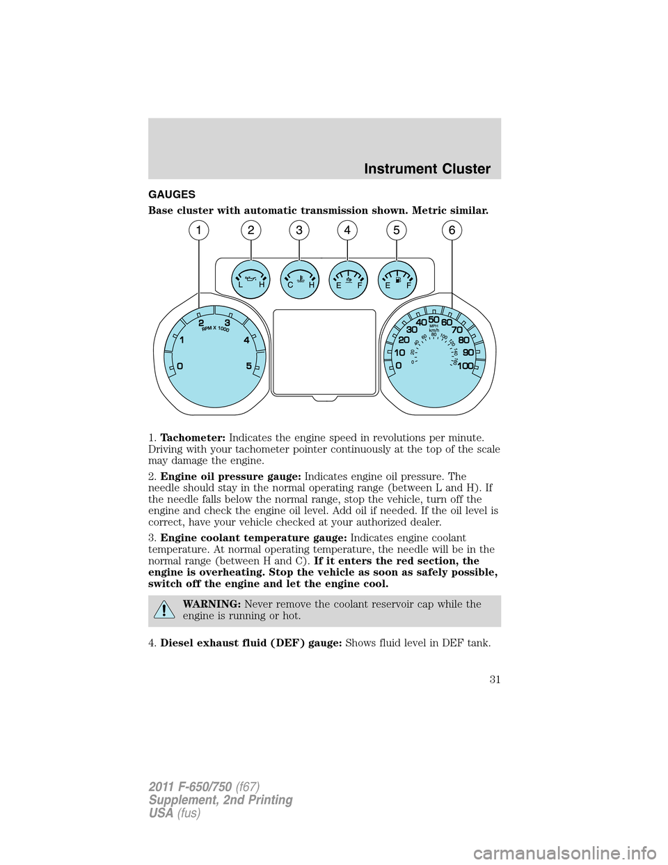
GAUGES
Base cluster with automatic transmission shown. Metric similar.
1.Tachometer:Indicates the engine speed in revolutions per minute.
Driving with your tachometer pointer continuously at the top of the scale
may damage the engine.
2.Engine oil pressure gauge:Indicates engine oil pressure. The
needle should stay in the normal operating range (between L and H). If
the needle falls below the normal range, stop the vehicle, turn off the
engine and check the engine oil level. Add oil if needed. If the oil level is
correct, have your vehicle checked at your authorized dealer.
3.Engine coolant temperature gauge:Indicates engine coolant
temperature. At normal operating temperature, the needle will be in the
normal range (between H and C).If it enters the red section, the
engine is overheating. Stop the vehicle as soon as safely possible,
switch off the engine and let the engine cool.
WARNING:Never remove the coolant reservoir cap while the
engine is running or hot.
4.Diesel exhaust fluid (DEF) gauge:Shows fluid level in DEF tank.
Instrument Cluster
31
2011 F-650/750(f67)
Supplement, 2nd Printing
USA(fus)
Page 102 of 290
If the booster seat slides on the vehicle seat, placing a rubberized mesh
sold as shelf or carpet liner under the booster seat may improve this
condition. Do not introduce any item thicker than this under the booster
seat. Check with the booster seat manufacturer’s instructions.
The importance of shoulder belts
Using a booster without a shoulder belt increases the risk of a child’s
head hitting a hard surface in a collision. For this reason, you should
never use a booster seat with a lap belt only. It is generally best to use a
booster seat with lap/shoulder belts in the back seat.
Move a child to a different seating location if the shoulder belt does not
stay positioned on the shoulder during use.
Follow all instructions provided by the manufacturer of the booster seat.
WARNING:Never place, or allow a child to place, the shoulder
belt under a child’s arm or behind the back because it reduces
the protection for the upper part of the body and may increase the risk
of injury or death in a collision.
Safety belt maintenance
Inspect the vehicle safety belts and child safety seat systems periodically
to make sure they work properly and are not damaged. Inspect the
vehicle and child seat safety belts to make sure there are no nicks, tears
or cuts. Replace if necessary. All vehicle safety belt assemblies, including
retractors, buckles, front safety belt buckle assemblies, buckle support
assemblies (slide bar-if equipped), shoulder belt height adjusters (if
equipped), shoulder belt guide on seatback (if equipped), child safety
seat LATCH and tether anchors, and attaching hardware, should be
inspected after a collision. Refer to the child restraint manufacturer’s
instructions for additional inspection and maintenance information
specific to the child restraint. Ford Motor Company recommends that all
safety belt assemblies in use in vehicles involved in a collision be
replaced. However, if the collision was minor and an authorized dealer
finds that the belts do not show damage and continue to operate
properly, they do not need to be replaced. Safety belt assemblies not in
use during a collision should also be inspected and replaced if either
damage or improper operation is noted.
For proper care of soiled safety belts, refer toInteriorin theCleaning
chapter.
Seating and Safety Restraints
102
2011 F-650/750(f67)
Supplement, 2nd Printing
USA(fus)
Page 105 of 290
Note:When starting the engine, do not press the accelerator as engine
damage may result.
1. Ensure headlamps and all accessories are turned off, the parking
brake is applied and the transmission is in the neutral position (or P
[Park] for Allison 2200 transmissions).
2. Turn the key to the on position, but do not start the engine.
In cooler weather, the air intake
heater may activate the WAIT TO
START light in the instrument
cluster. If the WAIT TO START light
illuminates,do notcrank the engine until the light goes off.
WARNING:If equipped with an air intake heater, DO NOT use
ether or any other starting fluids. The use of starting fluids
(ether) in an engine equipped with an air intake heater could cause an
explosion and result in property damage and/or personal injury.
3. When the WAIT TO START light turns off, turn the key to the start
position; when the engine starts, release the key.
If the engine does not start after 30 seconds of cranking, allow two
minutes for the starter to cool before trying again. Excessive cranking
may damage the starter.
After the engine starts:
•On some engines, the WAIT TO
START light should illuminate
after the engine starts. Allow the
engine to idle about three
minutes or until the engine coolant temperature gauge begins to rise.
Maintain idle speed until the WAIT TO START light cycles off to
indicate the air intake heater has shut off (approximately six
minutes). Operating the engine at higher speeds will reduce the
effectiveness of the air inlet heater.
•Do not increase engine speed until the oil pressure gauge indicates
normal pressure (as indicated by the arrows); this should be indicated
on the gauge within 15 seconds after starting.
•Idle the engine for three to five minutes before operating with a full
load.
•Try to limit engine idle to 10 minutes. Excessive idling reduces fuel
economy.
Driving
105
2011 F-650/750(f67)
Supplement, 2nd Printing
USA(fus)
Page 106 of 290
•When starting a cold engine, increase the engine RPM slowly to make
sure adequate lubrication is available to the bearings.
Cold weather operation
WARNING:Do not use volatile starting aids such as ether,
propane or gasoline in the engine air intake system. Glow plugs
may ignite vapors which can cause engine damage or personal injury.
In order to operate the engine in temperatures of 32°F (0°C) or lower,
read the following instructions:
•Make sure that the batteries are of sufficient size and are fully
charged. Check other electrical components to make sure they’re in
optimum condition.
•Use a permanent-type engine coolant solution to protect the engine
against damage from freezing.
•If your vehicle is equipped with a water-fuel separator, drain it daily.
Fill the fuel tank at the end of daily operation to prevent condensation
in the fuel system.
•Make sure you use proper cold weather engine oil and that it is at its
proper level.
•At temperatures of –4°F (–20°C) or below, it is recommended that you
use a crankcase-mounted coolant heater to improve cold engine
starting.
•If operating in arctic temperatures of –20°F (–29°C) or lower, consult
your truck dealer for information about special cold weather
equipment and precautions.
Note:Idling in cold weather will not heat the engine to its normal
operating temperature. Long periods of idling in cold weather can cause
a build-up of heavy deposits of carbon and rust on valve stems causing
them to stick which, in turn, can cause valvetrain damage.
Winter fronts
The use of winter fronts, or other air-restrictive devices mounted in front
of the radiator on vehicles with chassis-mounted charge air coolers, are
not recommended unless extremely cold weather conditions exist. Air
flow restriction can cause high exhaust temperatures, power loss,
excessive fan usage and a reduction in fuel economy. If you must use a
winter front, the device should have a permanent opening of at least 120
sq in. (774 sq. cm) directly in line with the fan hub.
Driving
106
2011 F-650/750(f67)
Supplement, 2nd Printing
USA(fus)