compressor FORD F750 2013 12.G Owners Manual
[x] Cancel search | Manufacturer: FORD, Model Year: 2013, Model line: F750, Model: FORD F750 2013 12.GPages: 378, PDF Size: 3.82 MB
Page 16 of 378
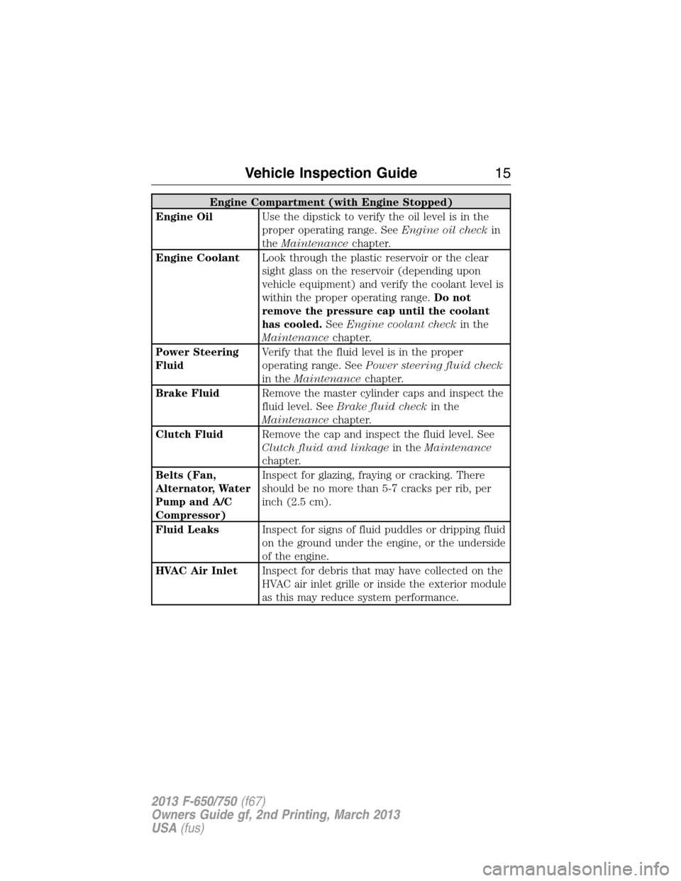
Engine Compartment (with Engine Stopped)
Engine OilUse the dipstick to verify the oil level is in the
proper operating range. SeeEngine oil checkin
theMaintenancechapter.
Engine CoolantLook through the plastic reservoir or the clear
sight glass on the reservoir (depending upon
vehicle equipment) and verify the coolant level is
within the proper operating range.Do not
remove the pressure cap until the coolant
has cooled.SeeEngine coolant checkin the
Maintenancechapter.
Power Steering
FluidVerify that the fluid level is in the proper
operating range. SeePower steering fluid check
in theMaintenancechapter.
Brake FluidRemove the master cylinder caps and inspect the
fluid level. SeeBrake fluid checkin the
Maintenancechapter.
Clutch FluidRemove the cap and inspect the fluid level. See
Clutch fluid and linkagein theMaintenance
chapter.
Belts (Fan,
Alternator, Water
Pump and A/C
Compressor)Inspect for glazing, fraying or cracking. There
should be no more than 5-7 cracks per rib, per
inch (2.5 cm).
Fluid LeaksInspect for signs of fluid puddles or dripping fluid
on the ground under the engine, or the underside
of the engine.
HVAC Air InletInspect for debris that may have collected on the
HVAC air inlet grille or inside the exterior module
as this may reduce system performance.
Vehicle Inspection Guide15
2013 F-650/750(f67)
Owners Guide gf, 2nd Printing, March 2013
USA(fus)
Page 17 of 378
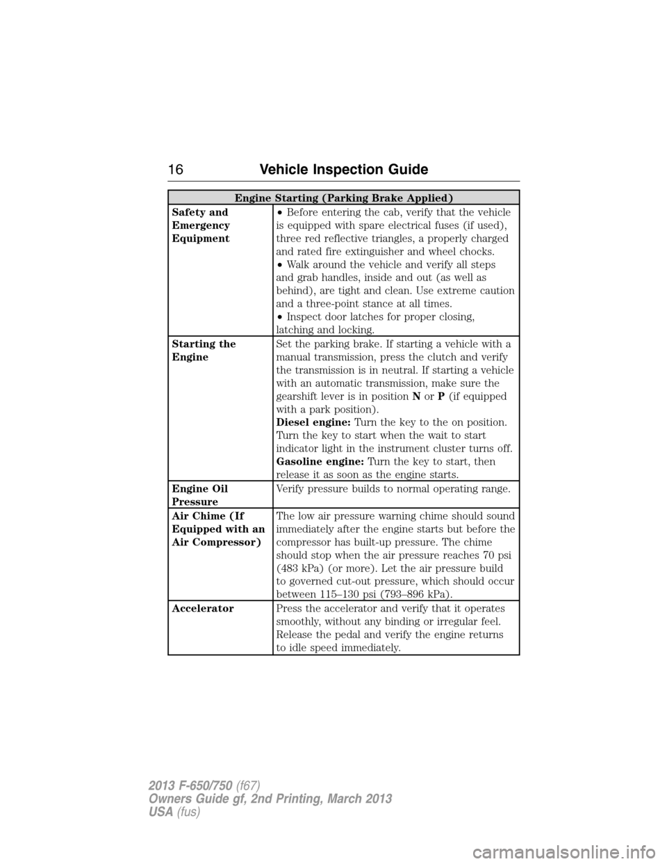
Engine Starting (Parking Brake Applied)
Safety and
Emergency
Equipment•Before entering the cab, verify that the vehicle
is equipped with spare electrical fuses (if used),
three red reflective triangles, a properly charged
and rated fire extinguisher and wheel chocks.
•Walk around the vehicle and verify all steps
and grab handles, inside and out (as well as
behind), are tight and clean. Use extreme caution
and a three-point stance at all times.
•Inspect door latches for proper closing,
latching and locking.
Starting the
EngineSet the parking brake. If starting a vehicle with a
manual transmission, press the clutch and verify
the transmission is in neutral. If starting a vehicle
with an automatic transmission, make sure the
gearshift lever is in positionNorP(if equipped
with a park position).
Diesel engine:Turn the key to the on position.
Turn the key to start when the wait to start
indicator light in the instrument cluster turns off.
Gasoline engine:Turn the key to start, then
release it as soon as the engine starts.
Engine Oil
PressureVerify pressure builds to normal operating range.
Air Chime (If
Equipped with an
Air Compressor)The low air pressure warning chime should sound
immediately after the engine starts but before the
compressor has built-up pressure. The chime
should stop when the air pressure reaches 70 psi
(483 kPa) (or more). Let the air pressure build
to governed cut-out pressure, which should occur
between 115–130 psi (793–896 kPa).
AcceleratorPress the accelerator and verify that it operates
smoothly, without any binding or irregular feel.
Release the pedal and verify the engine returns
to idle speed immediately.
16Vehicle Inspection Guide
2013 F-650/750(f67)
Owners Guide gf, 2nd Printing, March 2013
USA(fus)
Page 19 of 378
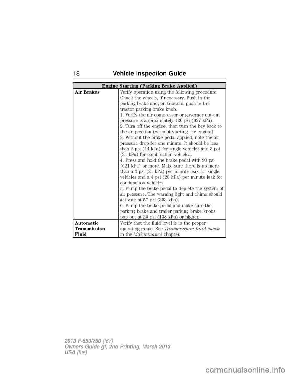
Engine Starting (Parking Brake Applied)
Air BrakesVerify operation using the following procedure.
Chock the wheels, if necessary. Push in the
parking brake and, on tractors, push in the
tractor parking brake knob:
1. Verify the air compressor or governor cut-out
pressure is approximately 120 psi (827 kPa).
2. Turn off the engine, then turn the key back to
the on position (without starting the engine).
3. Without the brake pedal applied, note the air
pressure drop for one minute. It should be less
than 2 psi (14 kPa) for single vehicles and 3 psi
(21 kPa) for combination vehicles.
4. Press and hold the brake pedal with 90 psi
(621 kPa) or more. Make sure there is no more
than a 3 psi (21 kPa) per minute leak for single
vehicles and a 4 psi (28 kPa) per minute leak for
combination vehicles.
5. Pump the brake pedal to deplete the system of
air pressure. The warning light and chime should
activate at 57 psi (393 kPa).
6. Pump the brake pedal and make sure the
parking brake and trailer parking brake knobs
pop out at 20 psi (138 kPa) or higher.
Automatic
Transmission
FluidVerify that the fluid level is in the proper
operating range. SeeTransmission fluid check
in theMaintenancechapter.
18Vehicle Inspection Guide
2013 F-650/750(f67)
Owners Guide gf, 2nd Printing, March 2013
USA(fus)
Page 91 of 378
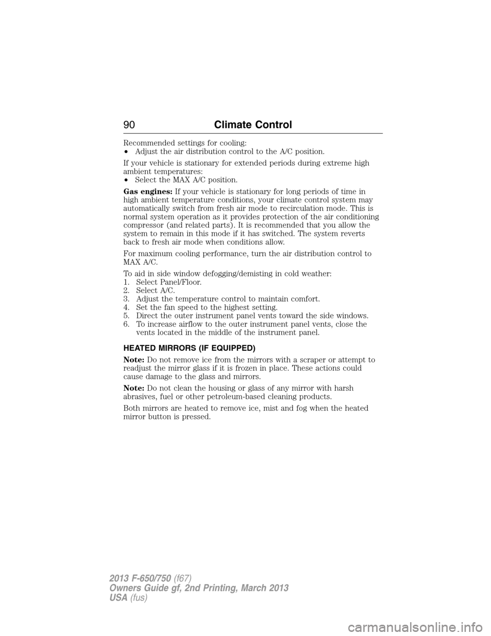
Recommended settings for cooling:
•Adjust the air distribution control to the A/C position.
If your vehicle is stationary for extended periods during extreme high
ambient temperatures:
•Select the MAX A/C position.
Gas engines:If your vehicle is stationary for long periods of time in
high ambient temperature conditions, your climate control system may
automatically switch from fresh air mode to recirculation mode. This is
normal system operation as it provides protection of the air conditioning
compressor (and related parts). It is recommended that you allow the
system to remain in this mode if it has switched. The system reverts
back to fresh air mode when conditions allow.
For maximum cooling performance, turn the air distribution control to
MAX A/C.
To aid in side window defogging/demisting in cold weather:
1. Select Panel/Floor.
2. Select A/C.
3. Adjust the temperature control to maintain comfort.
4. Set the fan speed to the highest setting.
5. Direct the outer instrument panel vents toward the side windows.
6. To increase airflow to the outer instrument panel vents, close the
vents located in the middle of the instrument panel.
HEATED MIRRORS (IF EQUIPPED)
Note:Do not remove ice from the mirrors with a scraper or attempt to
readjust the mirror glass if it is frozen in place. These actions could
cause damage to the glass and mirrors.
Note:Do not clean the housing or glass of any mirror with harsh
abrasives, fuel or other petroleum-based cleaning products.
Both mirrors are heated to remove ice, mist and fog when the heated
mirror button is pressed.
90Climate Control
2013 F-650/750(f67)
Owners Guide gf, 2nd Printing, March 2013
USA(fus)
Page 149 of 378
Anti-lock Brake System (ABS)
This system helps you maintain steering control during emergency stops
by keeping the brakes from locking.
The ABS lamp momentarily illuminates when the ignition is
turned on. If the light does not illuminate during start-up,
remains on or flashes, the ABS may be disabled and may need
to be serviced.
If the ABS is disabled, normal braking is still effective. If the
brake warning lamp illuminates, have your brake system
serviced immediately.
If a PLC trailer is connected when the ignition is switched on,
the trailer ABS light also illuminates. If the light fails to
illuminate, remains on after the vehicle is started or continues
to flash, have the system serviced immediately.
FULL POWER BRAKE SYSTEM
WARNING:If the red BRAKE warning lamp in the instrument
cluster remains illuminated after engine start up, this indicates a
system failure in the Full Power Brake System. Stop the vehicle safely
as soon as possible and seek service immediately.
This system incorporates standard braking, an anti-lock braking system
(ABS) and optional Power Park Brake into one fully-integrated hydraulic
brake system. With the Full Power Brake System, braking energy is
stored, similar to an air brake system, resulting in faster response times
and shorter stopping distances. This is accomplished using motor and
pump assemblies that pressurize the system by pumping brake fluid into
accumulators. This is similar to the air compressor of an air brake system
pressurizing the air tanks. The system includes a master cylinder that
provides the normal pedal feel and transfers the pedal force, via brake
fluid, to the main components of the system.
Note:The motor and pumps run momentarily with the ignition switch in
the on or run position, or in the off position with the brake pedal
pressed.
Note:During normal driving, the pump and motors may be heard
replenishing the accumulators. This is a normal function of the system.
148Brakes
2013 F-650/750(f67)
Owners Guide gf, 2nd Printing, March 2013
USA(fus)
Page 150 of 378
AIR BRAKES
After starting the engine, give the air compressor time to build up the air
pressure to 60 psi (414 kPa) before moving the vehicle.
WARNING:Do not drive or continue to drive if the low air
pressure buzzer is sounding or the brake warning light is lit.
These warnings indicate that air pressure is not to normal operating
level. Continued use of the vehicle could result in loss of braking ability.
WARNING:Avoid repeated light application of the brake pedal.
This depletes air pressure faster and could result in loss of
braking capability.
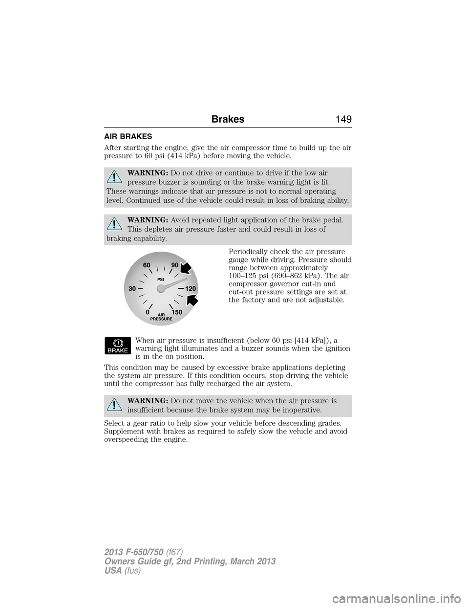
Periodically check the air pressure
gauge while driving. Pressure should
range between approximately
100–125 psi (690–862 kPa). The air
compressor governor cut-in and
cut-out pressure settings are set at
the factory and are not adjustable.
When air pressure is insufficient (below 60 psi [414 kPa]), a
warning light illuminates and a buzzer sounds when the ignition
is in the on position.
This condition may be caused by excessive brake applications depleting
the system air pressure. If this condition occurs, stop driving the vehicle
until the compressor has fully recharged the air system.
WARNING:Do not move the vehicle when the air pressure is
insufficient because the brake system may be inoperative.
Select a gear ratio to help slow your vehicle before descending grades.
Supplement with brakes as required to safely slow the vehicle and avoid
overspeeding the engine.
Brakes149
2013 F-650/750(f67)
Owners Guide gf, 2nd Printing, March 2013
USA(fus)
Page 202 of 378
Relay Center
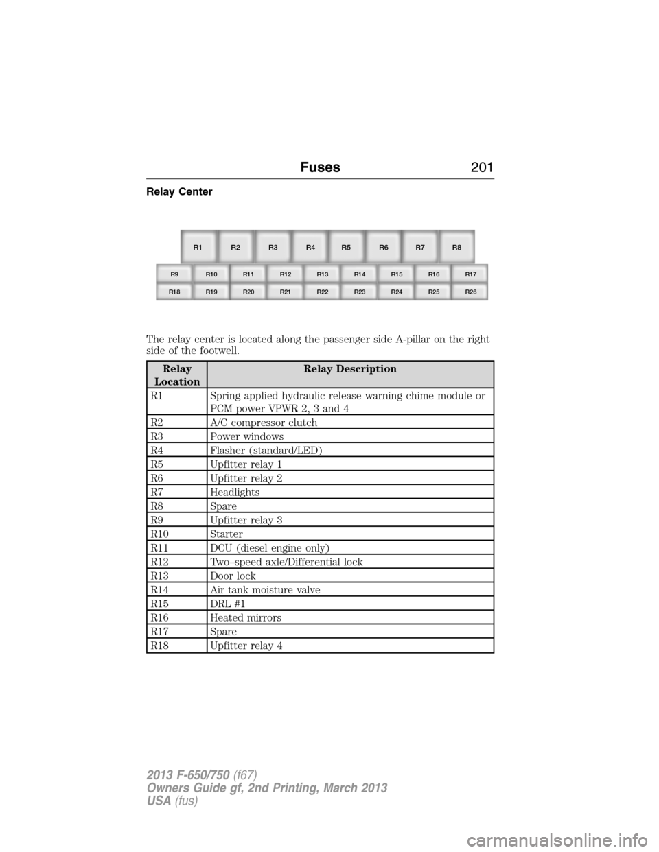
The relay center is located along the passenger side A-pillar on the right
side of the footwell.
Relay
LocationRelay Description
R1 Spring applied hydraulic release warning chime module or
PCM power VPWR 2, 3 and 4
R2 A/C compressor clutch
R3 Power windows
R4 Flasher (standard/LED)
R5 Upfitter relay 1
R6 Upfitter relay 2
R7 Headlights
R8 Spare
R9 Upfitter relay 3
R10 Starter
R11 DCU (diesel engine only)
R12 Two–speed axle/Differential lock
R13 Door lock
R14 Air tank moisture valve
R15 DRL #1
R16 Heated mirrors
R17 Spare
R18 Upfitter relay 4
R1
R9 R10 R11 R12 R13 R14 R15 R16 R17
R18 R19 R20 R21 R22 R23 R24 R25 R26
R2 R3 R4 R5 R6 R7 R8
Fuses201
2013 F-650/750(f67)
Owners Guide gf, 2nd Printing, March 2013
USA(fus)
Page 211 of 378
Some parts such as air brake chamber diaphragm, air compressor and air
cleaner should be inspected periodically and replaced if considered
unserviceable.
Air dryer:Climactic conditions affect performance of desiccant or
after-cooler type air dryers. Maintenance schedules must be established
for each specific operation.
The use of an air dryer on a vehicle does not eliminate the need to
periodically drain the air reservoirs.
Desiccant air dryer:Inspect for moisture in the air system by opening
reservoirs, draincocks or valves and checking for presence of water. The
presence of small amounts of water due to condensation is normal and
should not be considered as an indication that the dryer is not
functioning properly.
The desiccant cartridge should be replaced or rebuilt when it has been
determined that the desiccant is contaminated and does not have
adequate water absorption capacity. The desiccant change interval may
vary. It is generally recommended that the desiccant be replaced every
12 months (yearly). If experience has shown that extended or shortened
life has resulted for a particular installation, then the yearly interval can
be increased or decreased accordingly.
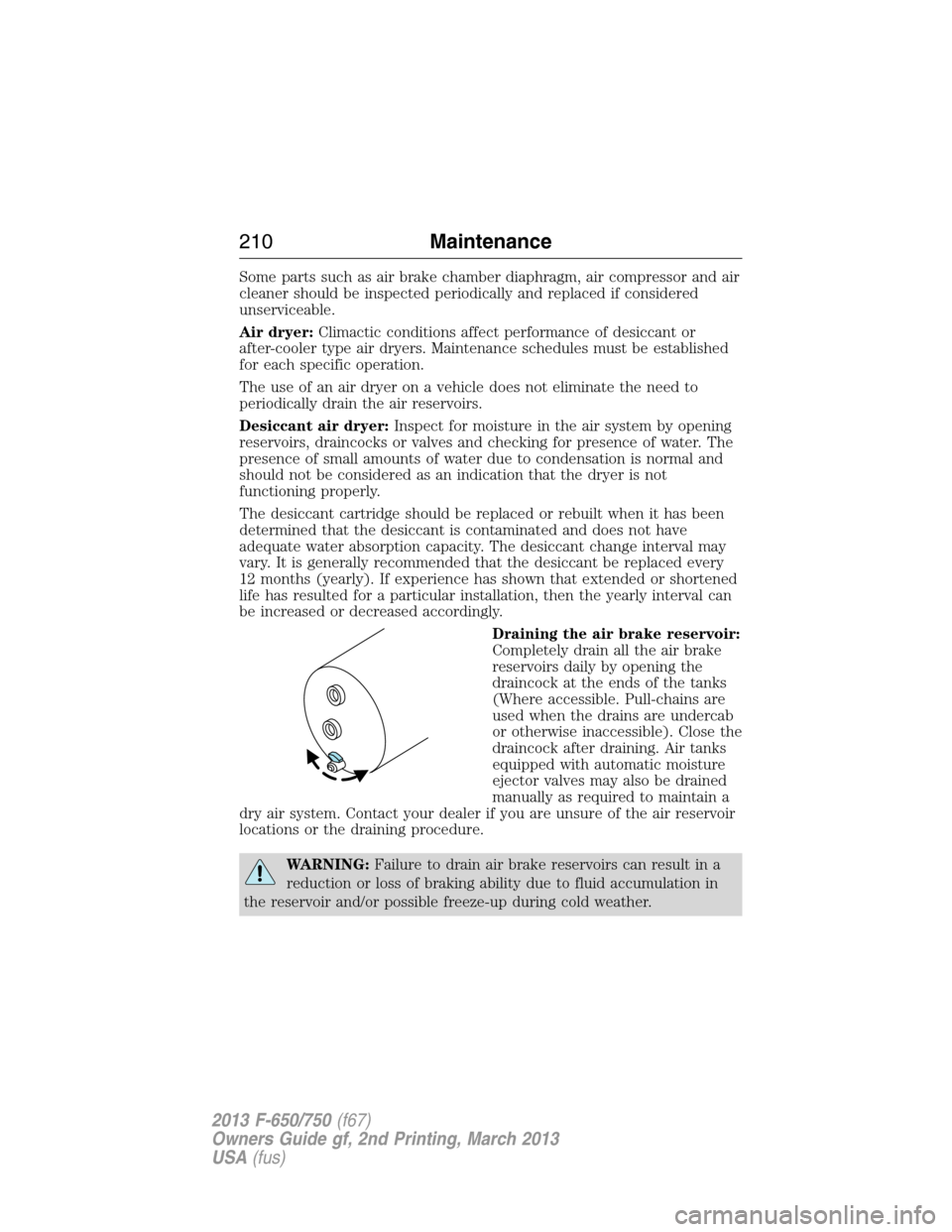
Draining the air brake reservoir:
Completely drain all the air brake
reservoirs daily by opening the
draincock at the ends of the tanks
(Where accessible. Pull-chains are
used when the drains are undercab
or otherwise inaccessible). Close the
draincock after draining. Air tanks
equipped with automatic moisture
ejector valves may also be drained
manually as required to maintain a
dry air system. Contact your dealer if you are unsure of the air reservoir
locations or the draining procedure.
WARNING:Failure to drain air brake reservoirs can result in a
reduction or loss of braking ability due to fluid accumulation in
the reservoir and/or possible freeze-up during cold weather.
210Maintenance
2013 F-650/750(f67)
Owners Guide gf, 2nd Printing, March 2013
USA(fus)
Page 214 of 378
Catalytic Converter (Diesel Engine)
Note:If your vehicle is equipped with a catalytic converter/muffler,do
notblend waste oil with diesel fuel. Operate only on ultra low sulfur
(less than 15 parts per million sulfur) diesel fuel with a cetane value of
45 or higher.
If your diesel engine is equipped with a catalytic converter, it is
important to review the maintenance schedule to make sure proper
functioning of the catalytic converter. Also, take precautions not to
damage the catalytic converter when servicing your engine or storing
your vehicle.
Diesel Exhaust Fluid (DEF), Diesel Particulate Filter (DPF) and
Select Catalyst Reduction (SCR) System
See your engine operator’s manual for information regarding DEF, DPF
and SCR system service.
Air Induction System
WARNING:When performing maintenance to any turbocharged
engine with engine air inlet piping disconnected, keep loose
clothing, jewelry and long hair away from the engine air inlet piping.
A turbocharger compressor air inlet protective shield should be
installed over the turbocharger air inlet to reduce the risk of personal
injury or death.
Perform a complete inspection of the air induction system annually.
In areas where road salt is used, disassemble the joints of each aluminum
component and inspect for salt build-up and presence of chlorine that
can cause aluminum particles to flake off and enter the engine
combustion chambers. If evidence of corrosion is found (usually at the
pipe connections), use a wire brush to clean the inside of the pipes and
inside the rubber hoses.
If the intake pipes are pitted at the joint ends, use Motorcraft® Silicone
Gasket and Sealant TA-30 to seal the joints. Make sure no excess
material is on the inside of the pipes that can be pulled into the engine.
If the service condition of the pipes, hoses or clamps is questionable,
replace the defective part(s).
Make sure all dust and debris has been cleaned out of the pipes and
couplings with a clean, damp rag prior to reassembly.
Maintenance213
2013 F-650/750(f67)
Owners Guide gf, 2nd Printing, March 2013
USA(fus)
Page 256 of 378
Checking Tire Pressure
Always check inflation pressure when tires are cold. Never bleed air from
hot tires to relieve normal pressure build-up. Normal increase in pressure
due to service conditions is 10–15 psi (69–103 kPa), which is allowable
in truck tires.
Tires should be properly inflated to manufacturers’ recommended
pressure for the size and service load in which the vehicle is being used.
See the specific tire manufacturer with which your vehicle is equipped
with for the latest information concerning service load and inflation
pressure.
It is particularly important to keep moisture from the inside of tires, and
proper selection of air compressor equipment, proper air line routing,
and the use of shop air dryers is strongly recommended to avoid
moisture in the high pressure air used for tire inflation.
Under-inflation
Tires should not be permitted to become under-inflated. Increased
flexing due to under-inflation causes heat build-up within the tire
components. This leads to reduced strength, breakdown of the rubber
compounds, and possible separation of the tire components (i.e., ply and
tread separation and reduced retreadability).
Under-inflation is the primary cause of premature tire concerns including
sudden loss of air. In addition, low inflation causes an increase in rolling
resistance. This results in reduced fuel mileage, a loss in tread mileage,
and uneven wear due to increased tread movement. To determine proper
inflation, see the tire manufacturer load and inflation guide which can be
found on the tire manufacturer website or at your local truck tire dealer.
Tire Inspection
Check the tires for abnormal wear patterns and proper inflation
pressures. Cut or broken tire casings must be repaired or replaced.
Tires should also be inspected for the following conditions. If any are
present, the tire should be removed and repaired, retreaded or scrapped
as the condition indicates.
•Any blister, bump or raised portion anywhere on the surface of the
tire tread or sidewall (other than a bump made by a repair). These
indicate the start of internal separation.
•Any cut that reaches to the belt or ply cords, or any cut that is large
enough to grow in size and depth.
•Any nail or puncturing object.
•If any stone or object is held by a tread groove and is starting to drill
into the tread base, remove the object.
Wheels and Tires255
2013 F-650/750(f67)
Owners Guide gf, 2nd Printing, March 2013
USA(fus)