height FORD F750 2016 13.G User Guide
[x] Cancel search | Manufacturer: FORD, Model Year: 2016, Model line: F750, Model: FORD F750 2016 13.GPages: 379, PDF Size: 4.8 MB
Page 79 of 379
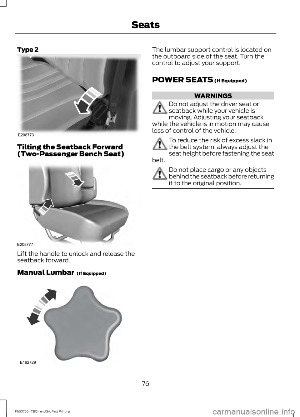
Type 2
Tilting the Seatback Forward
(Two-Passenger Bench Seat)
Lift the handle to unlock and release the
seatback forward.
Manual Lumbar (If Equipped) The lumbar support control is located on
the outboard side of the seat. Turn the
control to adjust your support.
POWER SEATS
(If Equipped)
WARNINGS
Do not adjust the driver seat or
seatback while your vehicle is
moving. Adjusting your seatback
while the vehicle is in motion may cause
loss of control of the vehicle. To reduce the risk of excess slack in
the belt system, always adjust the
seat height before fastening the seat
belt. Do not place cargo or any objects
behind the seatback before returning
it to the original position.
76
F650750 (TBC), enUSA, First Printing SeatsE208773 E208777 E162729
Page 80 of 379
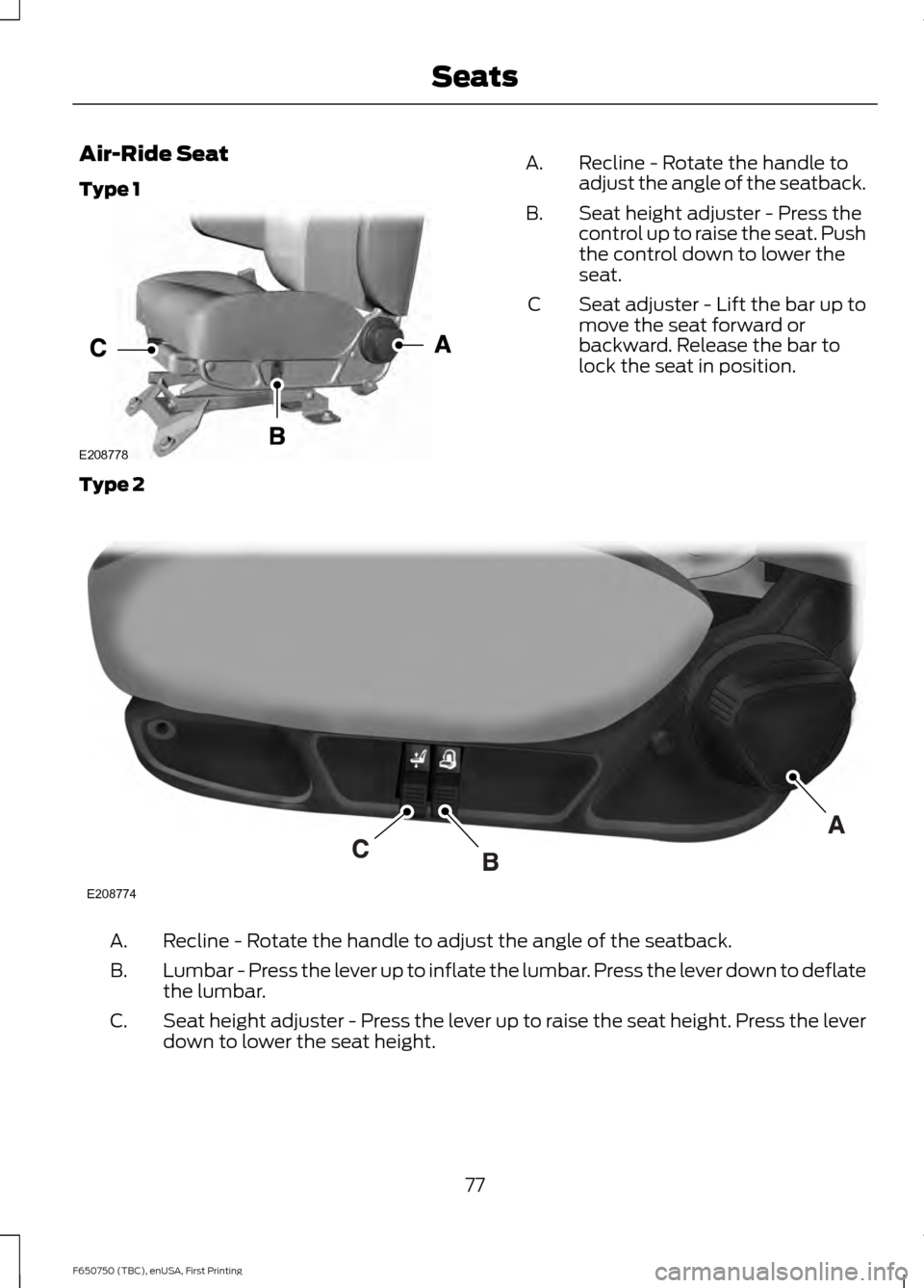
Air-Ride Seat
Type 1
Recline - Rotate the handle to
adjust the angle of the seatback.
A.
Seat height adjuster - Press the
control up to raise the seat. Push
the control down to lower the
seat.
B.
Seat adjuster - Lift the bar up to
move the seat forward or
backward. Release the bar to
lock the seat in position.
C
Type 2 Recline - Rotate the handle to adjust the angle of the seatback.
A.
Lumbar - Press the lever up to inflate the lumbar. Press the lever down to deflate
the lumbar.
B.
Seat height adjuster - Press the lever up to raise the seat height. Press the lever
down to lower the seat height.
C.
77
F650750 (TBC), enUSA, First Printing SeatsE208778 E208774
Page 141 of 379

AIR SUSPENSION (If Equipped)
Note: Do not operate your vehicle without
air in the suspension springs. Operating your
vehicle without air in the suspension springs
damages the suspension, degrades ride
performance and may cause property
damage.
The air suspension system automatically
adjusts to different loads to maintain a
constant frame height, allows for ease of
vehicle loading, provides improved vehicle
ride, and increased driver comfort.
Air Suspension Dump Button Note:
The suspension dumps air when the
ignition is in the accessory or on position,
but fills only when the ignition is in the on
position.
A button located on the instrument panel
controls the system. It operates only when
the ignition is in the accessory or on
position and the air tanks have sufficient
pressure to fill the air springs. When you
turn off the ignition, the suspension
remains in whatever state it was last set.
Pressing and holding the button for two
seconds exhausts air from the air springs,
lowering the frame for loading. Pressing
and holding the button for two seconds
fills the air springs so your vehicle remains
at normal ride height. System Indicator Light
The air suspension indicator light
illuminates when using the button to
release air pressure in the rear air springs.
Never drive your vehicle when the warning
lamp is illuminated and there is low (or no)
air pressure in the springs.
Connecting and Disconnecting a
Trailer with Air Suspension and Air
Suspension Dump Button
When connecting to a trailer:
•
Press and hold the button for two
seconds to exhaust air from the air
suspension system.
• Press and hold the button for two
seconds, and then raise the landing
gear after making the connection to
the trailer.
When disconnecting the trailer:
• Lower the landing gear, and then press
and hold the button for two seconds.
• Disconnect the brake hoses, trailer-side
and rear light connectors, then pull the
release lever on the fifth wheel.
You must fill the air springs before
operating with a trailer or operating in the
bobtail mode.
Suspension Conversions WARNING
When operating a loaded vehicle, the
driver must keep all adjustable axles
on the ground at all times, supporting
their share of the vehicle ’s load. Failure to
do so can overload other axles, tires,
wheels, springs, steering components,
brakes and frames, resulting in early
component failure, loss of vehicle control,
possible property damage and personal
injury. 138
F650750 (TBC), enUSA, First Printing Load CarryingE213409
Page 210 of 379

Headlamp Aiming Target
8 feet (2.4 meters)
A
Center height of lamp to ground
B
25 feet (7.6 meters)
C
Horizontal reference line
D
Vertical Aim Adjustment Procedure
1. Park the vehicle directly in front of a wall or screen on a level surface,
approximately 25 feet (7.6 meters)
away.
2. Measure the height of the headlamp bulb center from the ground and mark
an 8 foot (2.4 meter) horizontal
reference line on the vertical wall or
screen at this height.
Note: To see a clearer light pattern for
adjusting, you may want to block the light
from one headlamp while adjusting the
other.
3. Turn on the low beam headlamps to illuminate the wall or screen and open
the hood. 4. On the wall or screen you will observe
a flat zone of high intensity light
located at the top of the right hand
portion of the beam pattern. If the top
edge of the high intensity light zone is
not at the horizontal reference line, the
headlamp will need to be adjusted. 5. Locate the vertical adjuster on each
headlamp. Using a Phillips #2
screwdriver, turn the adjuster either
clockwise or counterclockwise in order
to adjust the vertical aim of the
headlamp.
6. Repeat steps 3 thru 5 to adjust the other headlamp.
7. Close the hood and turn off the lamps.
Horizontal Aim Adjustment
Horizontal aim is not required for this
vehicle and is not adjustable.
207
F650750 (TBC), enUSA, First Printing MaintenanceE142592 E142465 E163806
Page 225 of 379
Follow the tire manufacturer's
recommended cold inflation pressure for
the tire size, load range (ply rating) and
steer axle loading typical for their operation
(each steer axle tire equals ½ steer axle
loading).
Special applications may warrant a setting
based on experience with the type of tire
operating loads and conditions. Radial tires
are more sensitive to toe-in setting than
bias ply tires. Fine tuning school bus
alignment to line-haul truck standards
does not drastically improve tire tread life.
STEERING SYSTEM
INSPECTION
WARNING
Failure to maintain the steering
system in proper condition can cause
reduced steering ability resulting in
property damage, personal injury or death. Note:
Have any steering problems
immediately corrected by a qualified service
technician.
Ask your service technician to examine the
steering mechanism. Only minor
adjustments may be necessary.
Regular inspections should include:
• Checking the tie rod, drag link end
clamp bolts and ball joints for proper
tightness.
• Checking for installation and spread of
cotter pins and tightness of nuts at
both ends of the tie rod and drag link.
• Checking that the pitman arm (steering
arm at steering gear) mounting is tight
and locked. Check system for leaks or
hose chafing. Repair immediately, if
necessary. •
Maintaining proper steering gear and
power steering pump lubricant levels.
• Checking steering column joint bolts
and steering linkage, particularly for
body-to-chassis clearance.
Steering Column Joint Bolts
As a good maintenance practice, check
steering column joint bolt tightness every
60,000 mi (96,000 km) or annually,
whichever occurs first. Do not overtighten
the bolts.
Hydraulic System
Whenever draining and refilling the power
steering's hydraulic system for any reason,
bleed air from the system before returning
the vehicle to service. Failure to bleed the
hydraulic system properly can result in
degradation of power system performance.
Consult an authorized dealer who is aware
of the proper procedures for filling and
bleeding the system.
SUSPENSION SYSTEM
INSPECTION
Note: Do not adjust air suspension height
to any setting other than the specified
setting. Altering the height setting changes
the driveline angle and may result in
unwarrantable component damage, such
as transmission component damage.
Verify drive axle air suspension height and
height control valve performance at engine
oil change intervals.
Periodically check:
• Condition of spring leaves for evidence
of fatigue, bending or breakage.
• Condition of suspension mounting
brackets and bushings.
• Torque rod mounting fasteners for
tightness.
222
F650750 (TBC), enUSA, First Printing Maintenance
Page 236 of 379
describes the fundamental
characteristics of the tire and also
provides a U.S. DOT Tire
Identification Number for safety
standard certification and in case
of a recall.
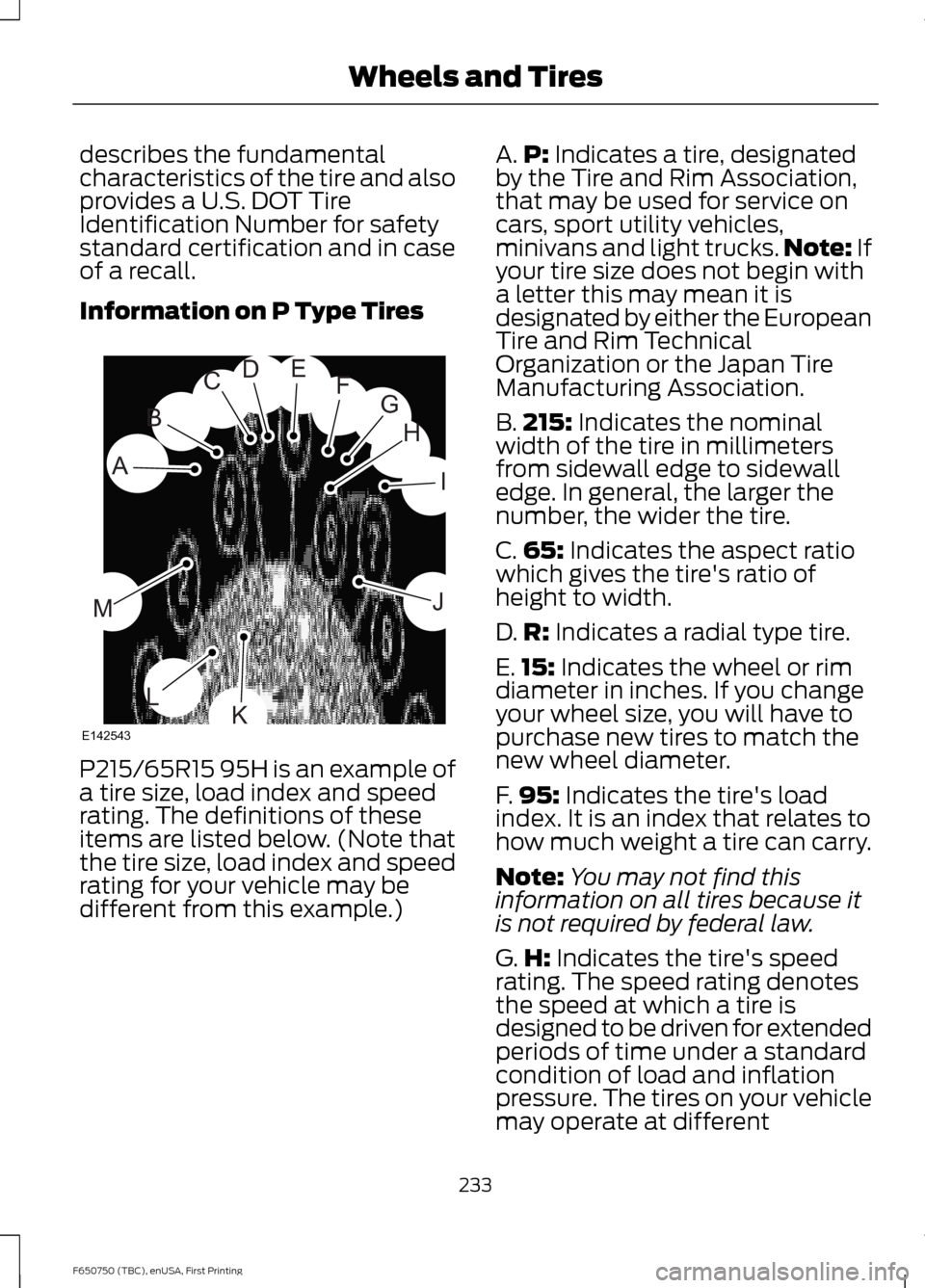
Information on P Type Tires
P215/65R15 95H is an example of
a tire size, load index and speed
rating. The definitions of these
items are listed below. (Note that
the tire size, load index and speed
rating for your vehicle may be
different from this example.) A.
P: Indicates a tire, designated
by the Tire and Rim Association,
that may be used for service on
cars, sport utility vehicles,
minivans and light trucks. Note:
If
your tire size does not begin with
a letter this may mean it is
designated by either the European
Tire and Rim Technical
Organization or the Japan Tire
Manufacturing Association.
B. 215:
Indicates the nominal
width of the tire in millimeters
from sidewall edge to sidewall
edge. In general, the larger the
number, the wider the tire.
C. 65:
Indicates the aspect ratio
which gives the tire's ratio of
height to width.
D. R:
Indicates a radial type tire.
E. 15:
Indicates the wheel or rim
diameter in inches. If you change
your wheel size, you will have to
purchase new tires to match the
new wheel diameter.
F. 95:
Indicates the tire's load
index. It is an index that relates to
how much weight a tire can carry.
Note: You may not find this
information on all tires because it
is not required by federal law.
G. H:
Indicates the tire's speed
rating. The speed rating denotes
the speed at which a tire is
designed to be driven for extended
periods of time under a standard
condition of load and inflation
pressure. The tires on your vehicle
may operate at different
233
F650750 (TBC), enUSA, First Printing Wheels and TiresH
I
J
KL
M
A
B
CDEFG
E142543
Page 240 of 379
C.
80: Indicates the aspect ratio
which gives the tire's ratio of
height to width. Numbers of 70 or
lower indicate a short sidewall.
D. D:
Indicates a diagonal type tire.
R:
Indicates a radial type tire.
E. 16:
Indicates the wheel or rim
diameter in inches. If you change
your wheel size, you will have to
purchase new tires to match the
new wheel diameter.
Inflating Your Tires
Safe operation of your vehicle
requires that your tires are
properly inflated. Remember that
a tire can lose up to half of its air
pressure without appearing flat.
Every day before you drive, check
your tires. If one looks lower than
the others, use a tire gauge to
check pressure of all tires and
adjust if required.
At least once a month and before
long trips, inspect each tire and
check the tire pressure with a tire
gauge (including spare, if
equipped). Inflate all tires to the
inflation pressure recommended
by Ford Motor Company.
You are strongly urged to buy a
reliable tire pressure gauge, as
automatic service station gauges
may be inaccurate. Ford
recommends the use of a digital
or dial-type tire pressure gauge
rather than a stick-type tire
pressure gauge. Use the recommended cold
inflation pressure for optimum tire
performance and wear.
Under-inflation or over-inflation
may cause uneven treadwear
patterns
WARNING
Under-inflation is the most
common cause of tire failures
and may result in severe tire
cracking, tread separation or
blowout, with unexpected loss of
vehicle control and increased risk
of injury. Under-inflation increases
sidewall flexing and rolling
resistance, resulting in heat
buildup and internal damage to
the tire. It also may result in
unnecessary tire stress, irregular
wear, loss of vehicle control and
accidents. A tire can lose up to
half of its air pressure and not
appear to be flat! Always inflate your tires to the
Ford recommended inflation
pressure even if it is less than the
maximum inflation pressure
information found on the tire. The
Ford recommended tire inflation
pressure is found on the Safety
Compliance Certification Label or
Tire Label. Failure to follow the tire
pressure recommendations can
cause uneven treadwear patterns
and adversely affect the way your
vehicle handles
237
F650750 (TBC), enUSA, First Printing Wheels and Tires
Page 245 of 379

Tire Wear
When the tread is worn down to
one sixteenth of an inch (2
millimeters), tires must be
replaced to help prevent your
vehicle from skidding and
hydroplaning. Built-in treadwear
indicators, or wear bars, which
look like narrow strips of smooth
rubber across the tread will
appear on the tire when the tread
is worn down to one sixteenth of
an inch (2 millimeters).
When the tire tread wears down
to the same height as these wear
bars, the tire is worn out and must
be replaced.
Damage
Periodically inspect the tire treads
and sidewalls for damage (such
as bulges in the tread or sidewalls,
cracks in the tread groove and
separation in the tread or
sidewall). If damage is observed or suspected have the tire
inspected by a tire professional.
Tires can be damaged during
off-road use, so inspection after
off-road use is also
recommended.
Age WARNING
Tires degrade over time
depending on many factors
such as weather, storage
conditions, and conditions of use
(load, speed, inflation pressure)
the tires experience throughout
their lives.
In general, tires should be
replaced after six years regardless
of tread wear. However, heat
caused by hot climates or
frequent high loading conditions
can accelerate the aging process
and may require tires to be
replaced more frequently.
You should replace your spare tire
when you replace the road tires or
after six years due to aging even if
it has not been used. U.S. DOT Tire Identification
Number
Both United States and Canada
Federal regulations require tire
manufacturers to place
standardized information on the
sidewall of all tires. This
information identifies and
242
F650750 (TBC), enUSA, First Printing Wheels and TiresE142546
Page 376 of 379

Replacement Parts
Recommendation........................................13
Collision Repairs.................................................... 13
Scheduled Maintenance and Mechanical Repairs.................................................................. 13
Warranty on Replacement Parts..................... 14
Replacing a Lost Key or Remote Control............................................................39
Reporting Safety Defects (Canada Only)................................................................161
Reporting Safety Defects (U.S. Only)..............................................................160
Roadside Assistance....................................151
Vehicles Sold in Canada: Getting Roadside
Assistance......................................................... 151
Vehicles Sold in Canada: Using Roadside Assistance......................................................... 151
Vehicles Sold in the United States: Getting Roadside Assistance..................................... 151
Vehicles Sold in the United States: Using Roadside Assistance..................................... 151
Roadside Emergencies................................151
Running-In See: Breaking-In.................................................. 146
Running Out of Fuel - 6.7L Diesel............95 Purging Air from the Fuel System.................. 95
Running Out of Fuel - 6.8L.........................95
S
Safety Precautions
........................................90
Low Fuel Pressure................................................. 91
Satellite Radio...............................................275 Satellite Radio Electronic Serial Number
(ESN)................................................................. 276
Satellite Radio Reception Factors...............275
SIRIUS® Satellite Radio Service.................. 275
Troubleshooting................................................. 276
Scheduled Maintenance Record...........335
Scheduled Maintenance............................314
Seatbelt Height Adjustment
......................34
Seatbelt Reminder.........................................35
Belt-Minder™........................................................ 35
Seatbelts...........................................................30 Principle of Operation........................................ 30
Seatbelt Warning Lamp and Indicator Chime...............................................................35
Conditions of operation..................................... 35Seats....................................................................73
Security..............................................................42
Selective Catalytic Reduction
System............................................................95
Contaminated Diesel Exhaust Fluid or Inoperative Selective Catalytic Reduction
System................................................................ 99
Diesel Exhaust Fluid Guidelines and Information....................................................... 98
Diesel Exhaust Fluid Warning Messages and Vehicle Operations................................. 97
Filling the Diesel Exhaust Fluid Tank............96
Importance of Maintaining the Diesel Exhaust Fluid Level........................................ 96
Sitting in the Correct Position....................73
Snow Chains See: Using Snow Chains................................. 246
Special Notices
................................................14
New Vehicle Limited Warranty......................... 14
Special Instructions.............................................. 14
Special Operating Conditions Scheduled Maintenance
...............................................326
Diesel Engine....................................................... 328
Exceptions............................................................ 333
Gasoline Engines............................................... 326
Speed Control See: Cruise Control............................................ 134
Spring U-Bolt Check...................................223 U-bolt and U-bolt Nut Installation..............224
U-bolt Checks and Re-torqueing
Procedures...................................................... 224
U-bolt Nut Torque............................................. 224
Starter Switch See: Ignition Switch............................................ 84
Starting a Diesel Engine..............................86 ........................................................................\
............ 86
Cold Weather Starting....................................... 86
Diesel Engine Fast Start Glow Plug System................................................................ 86
Starting a Gasoline Engine.........................85 Failure to Start...................................................... 85
Guarding Against Exhaust Fumes.................85
Important Ventilating Information................85
Stopping the Engine When Your Vehicle is Moving................................................................. 85
Stopping the Engine When Your Vehicle is Stationary.......................................................... 85
373
F650750 (TBC), enUSA, First Printing Index