service schedule FORD F750 2016 13.G User Guide
[x] Cancel search | Manufacturer: FORD, Model Year: 2016, Model line: F750, Model: FORD F750 2016 13.GPages: 379, PDF Size: 4.8 MB
Page 193 of 379
8.
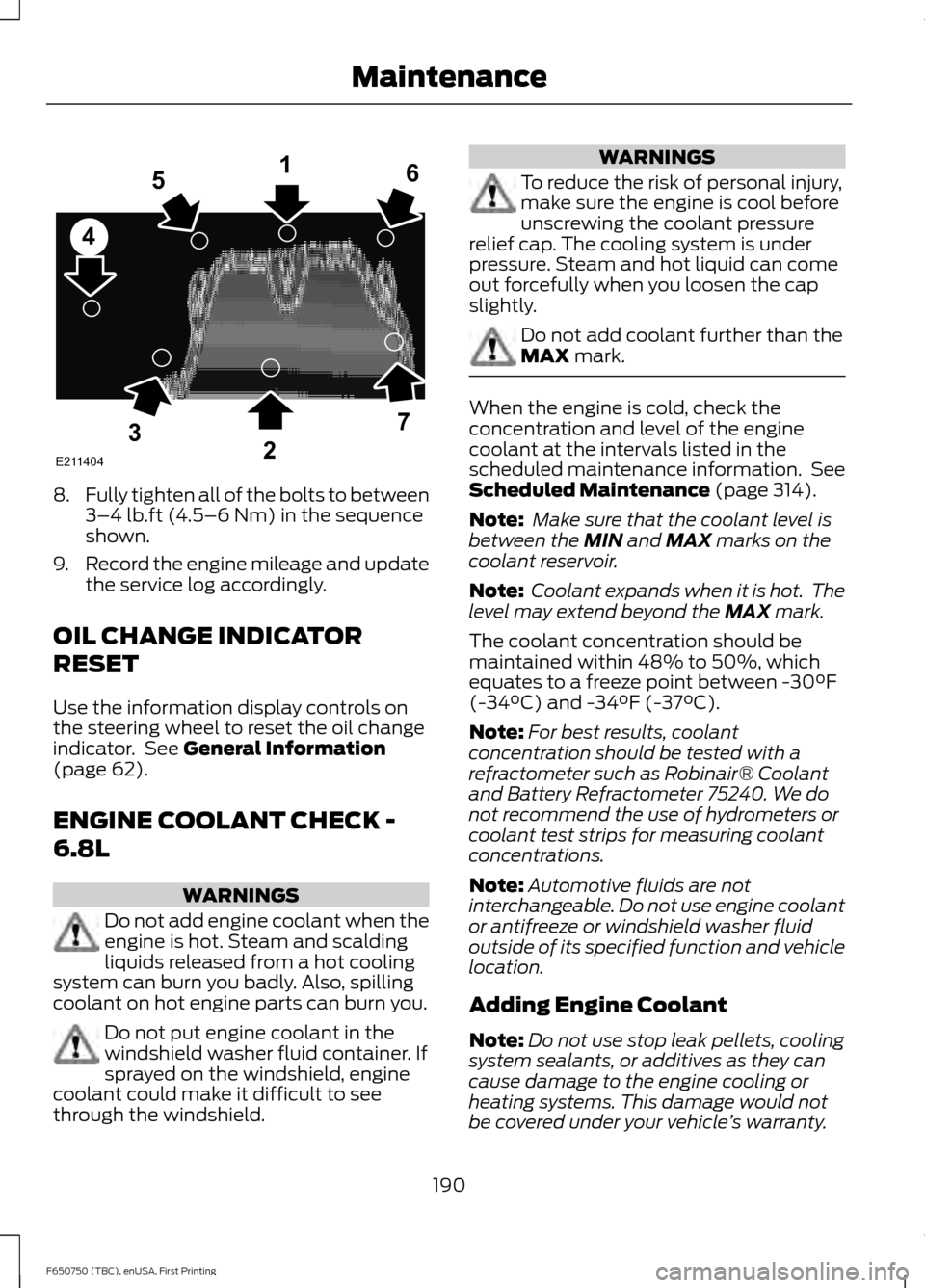
Fully tighten all of the bolts to between
3–4 lb.ft (4.5–6 Nm) in the sequence
shown.
9. Record the engine mileage and update
the service log accordingly.
OIL CHANGE INDICATOR
RESET
Use the information display controls on
the steering wheel to reset the oil change
indicator. See
General Information
(page 62).
ENGINE COOLANT CHECK -
6.8L WARNINGS
Do not add engine coolant when the
engine is hot. Steam and scalding
liquids released from a hot cooling
system can burn you badly. Also, spilling
coolant on hot engine parts can burn you. Do not put engine coolant in the
windshield washer fluid container. If
sprayed on the windshield, engine
coolant could make it difficult to see
through the windshield. WARNINGS
To reduce the risk of personal injury,
make sure the engine is cool before
unscrewing the coolant pressure
relief cap. The cooling system is under
pressure. Steam and hot liquid can come
out forcefully when you loosen the cap
slightly. Do not add coolant further than the
MAX
mark.
When the engine is cold, check the
concentration and level of the engine
coolant at the intervals listed in the
scheduled maintenance information. See
Scheduled Maintenance
(page 314).
Note: Make sure that the coolant level is
between the
MIN and MAX marks on the
coolant reservoir.
Note: Coolant expands when it is hot. The
level may extend beyond the
MAX mark.
The coolant concentration should be
maintained within 48% to 50%, which
equates to a freeze point between -30°F
(-34°C) and -34°F (-37°C).
Note: For best results, coolant
concentration should be tested with a
refractometer such as Robinair® Coolant
and Battery Refractometer 75240. We do
not recommend the use of hydrometers or
coolant test strips for measuring coolant
concentrations.
Note: Automotive fluids are not
interchangeable. Do not use engine coolant
or antifreeze or windshield washer fluid
outside of its specified function and vehicle
location.
Adding Engine Coolant
Note: Do not use stop leak pellets, cooling
system sealants, or additives as they can
cause damage to the engine cooling or
heating systems. This damage would not
be covered under your vehicle ’s warranty.
190
F650750 (TBC), enUSA, First Printing MaintenanceE211404
165
4
32
7
Page 203 of 379
AUTOMATIC TRANSMISSION
FLUID CHECK
Have an authorized dealer check and
change the transmission fluid and filter at
the correct service interval. See
Scheduled Maintenance (page 314).
Do not use supplemental transmission
fluid additives, treatments or cleaning
agents. The use of these materials may
affect transmission operation and result
in damage to internal transmission
components.
Checking Automatic Transmission
Fluid
Check and change the fluid at the
scheduled intervals. See
Scheduled
Maintenance (page 314). Your
transmission does not consume fluid.
However, the fluid level should be checked
if the transmission is not working properly,
such as if the transmission slips or shifts
slowly or if you notice some sign of fluid
leakage.
Automatic transmission fluid expands
when warmed. To obtain an accurate fluid
check, drive the vehicle until it is at normal
operating temperature, approximately
20 mi (30 km). Verify that the transmission
fluid temperature gauge, located on the
instrument cluster, is within normal range.
1. Drive the vehicle
20 mi (30 km)until it
reaches normal operating temperature.
2. Park the vehicle on a level surface and
engage the parking brake.
3. With the engine running, parking brake
engaged and your foot on the brake
pedal, move the gearshift lever through
all of the gear ranges. Allow sufficient
time for each gear to engage.
4. Latch the gearshift lever in park (P) or neutral (N) and leave the engine
running. 5. Remove the dipstick, wiping it clean
with a clean, dry lint free rag. If
necessary, refer to the Under Hood
Overview in this chapter for the
location of the dipstick.
6. Install the dipstick making sure it is fully
seated in the filler tube.
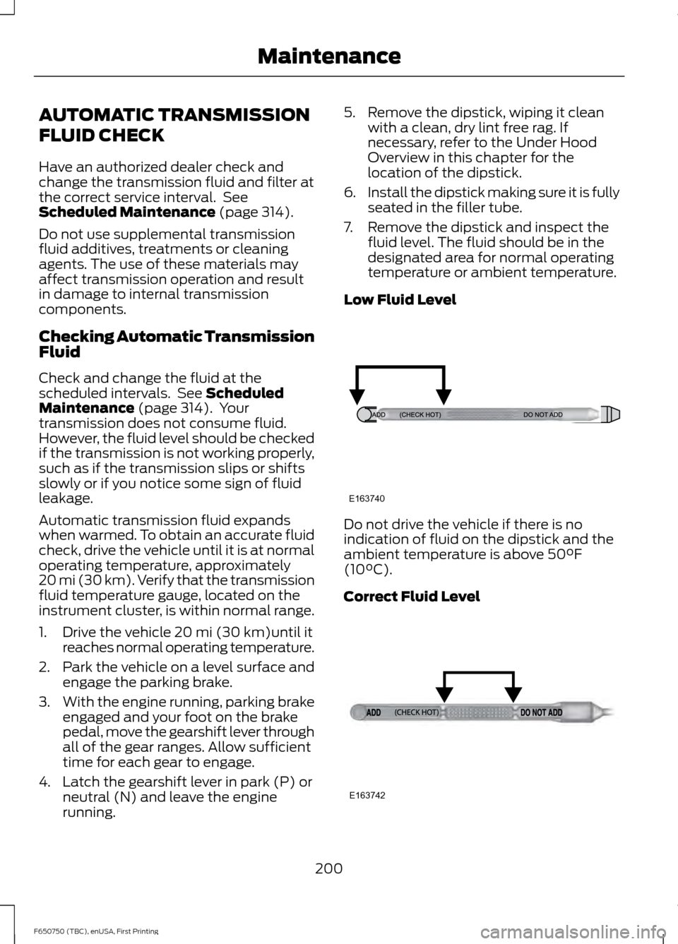
7. Remove the dipstick and inspect the fluid level. The fluid should be in the
designated area for normal operating
temperature or ambient temperature.
Low Fluid Level Do not drive the vehicle if there is no
indication of fluid on the dipstick and the
ambient temperature is above
50°F
(10°C).
Correct Fluid Level 200
F650750 (TBC), enUSA, First Printing MaintenanceE163740 E163742
Page 217 of 379
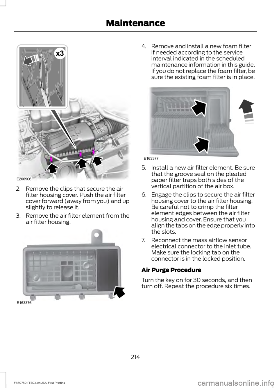
2. Remove the clips that secure the air
filter housing cover. Push the air filter
cover forward (away from you) and up
slightly to release it.
3. Remove the air filter element from the
air filter housing. 4. Remove and install a new foam filter
if needed according to the service
interval indicated in the scheduled
maintenance information in this guide.
If you do not replace the foam filter, be
sure the existing foam filter is in place. 5. Install a new air filter element. Be sure
that the groove seal on the pleated
paper filter traps both sides of the
vertical partition of the air box.
6. Engage the clips to secure the air filter housing cover to the air filter housing.
Be careful not to crimp the filter
element edges between the air filter
housing and cover. Ensure that you
align the tabs on the edge properly into
the slots.
7. Reconnect the mass airflow sensor electrical connector to the inlet tube.
Make sure the locking tab on the
connector is in the locked position.
Air Purge Procedure
Turn the key on for 30 seconds, and then
turn off. Repeat the procedure six times.
214
F650750 (TBC), enUSA, First Printing MaintenanceE206906
x3 E163376 E163377
Page 221 of 379
Make sure to clean all dust and debris out
of the pipes and couplings with a clean,
damp rag before reassembly.
Chassis-mounted Charge Air
Cooler
Visually inspect the core assembly for
debris and clogging of external fins with
the engine off.
Before engine operation, remove any debris
blocking the core.
•
Turbocharger-to-charge air cooler.
• Charge air cooler-to-intake manifold
pipe.
• Mounting bracket.
• Chassis-mounted charge air cooler
core.
Inspect air intake piping:
• Check for accumulation of salt
deposits (where applicable). If present,
disassemble and clean the complete
air intake piping system. If pitting is
evident on the intake piping, use
Motorcraft Silicone Gasket and Sealant
TA-30 to seal joints against leakage.
• Check for loose hoses and clamps.
• Check for ruptured or collapsed hoses.
• Check air cleaner housing for cracks.
EXHAUST SYSTEM
INSPECTION
Note: If your vehicle is equipped with a
catalytic converter or muffler, do not blend
waste oil with diesel fuel. Operate only on
ultra-low sulfur (less than 15 parts per
million sulfur) diesel fuel with a cetane
value of 45 or higher. If your diesel engine is equipped with a
catalytic converter, it is important to review
the maintenance schedule to make sure
proper functioning of the catalytic
converter. Also, take precautions not to
damage the catalytic converter when
servicing your engine or storing your
vehicle.
BRAKE SYSTEM INSPECTION
WARNING
Always wear a respirator approved
by the National Institute of
Occupational Studies of Health
(NIOSH) or Mine Safety and Appliance
(MSA) during all brake service procedures.
Wear the respirator from removal of the
wheels through assembly.
Never use compressed air or dry brushing
to clean brake parts or assemblies.
Clean brake parts and assemblies in open
air. During assembly, carefully place all
parts on the floor to avoid getting dust in
the air. Use an industrial vacuum cleaner
with a HEPA filter system to clean dust
from the brake drums, backing plates and
other brake parts. After using the vacuum,
remove any remaining dust with a rag
soaked in water and wrung until nearly dry.
Never use compressed air or dry sweeping
to clean the work area. Use an industrial
vacuum cleaner with a HEPA filter system
and rags soaked in water and wrung until
nearly dry. Dispose of used rags with care
to avoid getting dust in the air. Use an
approved respirator when emptying
vacuum cleaners and handling used rags.
Worker clean-up: Wash your hands before
eating, drinking or smoking. Vacuum your
work clothes after use and then launder
them separately, without shaking them, to
prevent fiber dust getting into the air. 218
F650750 (TBC), enUSA, First Printing Maintenance
Page 222 of 379
Your vehicle is equipped with
non-asbestos brake linings. However,
exposure to excessive amounts of brake
material (whether asbestos or
non-asbestos, fiberglass, mineral wool,
aramid or carbon) may be a serious health
hazard.
Air Brakes
WARNING
Do not manually adjust the
automatic slack adjusters to correct
excessive push rod stroke as it may
result in reduced brake effectiveness and
a vehicle crash. Excessive push rod stroke
indicates that a problem exists with the
automatic adjuster, with the installation
of the adjuster, or with foundation brake
components that manual adjustment does
not remedy. Seek service from a qualified
facility for excessive push rod stroke. Inspection and Adjustment
Establish a regular schedule for periodic
cleaning, lubrication and adjustment
inspection based on vehicle use. Exact
maintenance intervals are difficult to
predetermine due to vehicle applications
and operating conditions. If you are
uncertain of the proper schedule for your
vehicle, contact an authorized dealer.
Regular inspections should include:
•
Periodic checking (every service
interval) of push rod travel or brake
adjustment. This is essential for
effective braking. Brake chamber push
rods on original equipment chambers
now incorporate an orange paint
marker near the base of the push rod as a stroke indicator to aid in
adjustment checks. If the push rod is
clean and the brakes are out of
adjustment, you can see the orange
marker protruding from the chamber
when the brakes are applied.
• Checking the brake lining (every service
interval). When brake linings or blocks
wear within 0.063 in (1.6 mm) they
must be replaced.
• Periodic checking (every service
interval) of the air compressor filter.
Check the filter minder and when the
indicator is near or on the red line
marked
Service, replace the filter and
reset the service filter minder.
Do not back off or disconnect the front
brakes so that they are less effective,
letting the rear brakes do all the stopping
of your vehicle. Do not overlook the brakes
on the trailer either. Brake condition on the
trailer is just as important as the tractor.
Proper brake balance on trucks and
tractor-trailers is essential for effective
braking.
Once a year, inspect the entire brake
system:
• Rubber components for deterioration.
A qualified technician should inspect
these components and replace them
as necessary. Replacement intervals
vary according to the severity and
length of vehicle service.
• Condition of brake drums, brake
chambers and slack adjusters.
• System for air leaks.
• Hose or pipes for rust, damage and
deterioration.
• Operation of service and parking
brakes.
Periodically inspect parts such as air brake
chamber diaphragm, air compressor and
air cleaner. Replace any parts if you can
consider them unserviceable.
219
F650750 (TBC), enUSA, First Printing Maintenance
Page 223 of 379
Air Dryer
Climactic conditions affect performance
of desiccant or after-cooler type air dryers.
You must establish a maintenance
schedule for each specific operation.
The use of an air dryer on a vehicle does
not eliminate the need to drain the air
reservoirs periodically.
Inspect for moisture in the air system by
opening reservoirs, draincocks or valves
and checking for presence of water. The
presence of small amounts of water due
to condensation is normal and is not an
indication that the dryer is not functioning
properly.
Replace or rebuild the desiccant cartridge
when you determine that the desiccant is
contaminated and does not have adequate
water absorption capacity. The desiccant
change interval may vary. A general
recommendation is to replace the
desiccant every 12 months (yearly). If
experience has shown that extended or
shortened life has resulted for a particular
installation, then the yearly interval can be
increased or decreased accordingly.
Draining the Air Brake Reservoir
WARNING
Failure to drain air brake reservoirs
can result in a reduction or loss of
braking ability due to fluid
accumulation in the reservoir and/or
possible freeze-up during cold weather. Completely drain all the air brake reservoirs
daily by opening the draincock at the ends
of the tanks. (Where accessible.
Pull-chains are used when the drains are
undercab or otherwise inaccessible.) Close
the draincock after draining. Manually drain any air tanks equipped with automatic
moisture ejector valves, as required, to
maintain a dry air system. Contact an
authorized dealer if you are unsure of the
air reservoir locations or the draining
procedure.
Hydraulic Brakes
Establish a regular schedule for periodic
cleaning, lubrication and adjustment
inspection based on vehicle use. Exact
maintenance intervals are difficult to
predetermine due to vehicle applications
and operating conditions. If you are
uncertain of the proper schedule for your
vehicle, contact an authorized dealer.
Regular inspections should include:
•
Checking the brake lining (every service
interval). Establish inspection intervals
that provide for lining replacement
before damage to the disc occurs.
Excessive lining wear may expose the
backing plate to the disc causing
scoring of the disc faces. A qualified
technician should perform this
220
F650750 (TBC), enUSA, First Printing Maintenance
Page 224 of 379
inspection and keep to instructions
provided by the service manual.
Hydraulic brake systems are
power-assisted. There is a great
reduction in braking capabilities
without engine assist.
• Proper fluid level. The level should be
at the bottom edge of the ring on each
reservoir fill port. Do not fill the master
cylinder to the top of the reservoir. If
fluid level requires attention to
maintain a proper master cylinder level,
this is an indication of either severe
operation (pad wear) or fluid leakage.
A more frequent and thorough brake
inspection is required.
• Brake lines, hoses and fittings. Repair
or replace brake line tubes, hoses or
fittings as required. Inspect these
components every 4,000 mi
(6,000 km) for the following.
• Lines for kinks, dents, corrosion or
rupture.
• Hoses for abrasions, kinks, soft
spots or rupture, collapse, cracks,
twists or loose frame supports.
When replacing a hose, be sure
there is adequate clearance to the
hose to avoid an abrasion to the
new hose.
• All connections for leaks.
Driveline Parking Brake WARNING
Use wheel chocks and exercise
caution when inspecting under the
vehicle. A vehicle roll-away could
result in property damage, personal injury
or death. A qualified technician should adjust the
parking brake and keep to the instructions
in the service manual. AXLE INSPECTION
Front Axle
Maintaining the front axle alignment to
specifications is very important. A qualified
technician should check and maintain the
alignment.
Regular inspections should include:
•
Toe-in inspection and adjustment (if
necessary), particularly with radial
tires.
• Checking for proper tightness of axle
mounting U-bolt nuts, attaching or
mounting bolts and nuts.
• Checking the axle for damage, binding,
worn parts and adequate lubrication.
• Checking the kingpins for excessive
wear. Also, perform this check during
other scheduled maintenance, for
example as tire rotation or service,
wheel bearing service and alignment.
See the workshop manual for proper
procedures.
Toe-in
It is essential to maintain correct toe-in
and tire pressure for optimum tire wear.
Inspecting steer axle tires in the first
3,000– 10,000 mi (5,000– 16,000 km)
generally shows if tires are wearing
normally.
Rapid outside shoulder wear on both tires
indicates too much toe-in.
Rapid inside shoulder wear on both tires
indicates too much toe-out.
In P&D-type service, there can be a
left-to-right steer tire tread life differential
up to 40% depending on routes and other
variables.
221
F650750 (TBC), enUSA, First Printing Maintenance
Page 316 of 379
Avoid the Rising Cost of Properly
Maintaining Your Vehicle!
Ford Extended Service Plan also offers a
Premium Maintenance Plan that covers all
scheduled maintenance, and selected
wear items. The coverage is prepaid, so
you never have to worry about affording
your vehicle
’s maintenance. It covers
regular checkups, routine inspections,
preventive care and replacement of select
items that require periodic attention for
normal wear:
• Windshield wiper blades.
• Spark plugs.
• The clutch disc.
• Brake pads and linings.
• Shock absorbers.
• Struts.
• Engine Belts.
• Engine coolant hoses, clamps and
o-rings.
• Diesel exhaust fluid replenishment.
Interest Free Finance Options
Available
Take advantage of our interest free
installment payment plan. Just a 10%
down payment will provide you with an
affordable, no interest, no fee payment
program allowing you all the security and
benefits Ford ESP has to offer while paying
over time. You are pre-approved with no
credit checks, no hassles! To learn more,
call our Ford ESP specialists at
800-367-3377.
Ford ESP
P.O. Box 321067
Detroit, MI 48232 SERVICE PLANS (CANADA ONLY)
You can get more protection for your
vehicle by purchasing a Ford Extended
Service Plan. Ford Extended Service Plan
is the only service contract backed by Ford
Motor Company of Canada, Limited.
Depending on the plan you purchase, Ford
Extended Service Plan provides benefits
such as:
•
Rental reimbursement.
• Coverage for certain maintenance and
wear items.
• Protection against repair costs after
your New Vehicle Limited Warranty
Coverage expires.
• Roadside Assistance benefits.
There are several Ford Extended Service
Plans available in various time, distance
and deductible combinations. Each plan
is tailored to fit your own driving needs,
including reimbursement for towing and
rental. When you purchase Ford Extended
Service Plan, you receive added
peace-of-mind protection throughout
Canada, the United States and Mexico,
provided by a network of participating
authorized Ford Motor Company dealers.
Note: Repairs performed outside of
Canada, the United States and Mexico are
not eligible for Ford Extended Service Plan
coverage.
This information is subject to change. For
more information, visit your local Ford of
Canada dealer or www.ford.ca to find the
Ford Extended Service Plan that is right for
you.
313
F650750 (TBC), enUSA, First Printing Extended Service Plan (ESP)
Page 317 of 379
GENERAL MAINTENANCE
INFORMATION
Why Maintain Your Vehicle?
Carefully following the maintenance
schedule helps protect against major repair
expenses resulting from neglect or
inadequate maintenance and may help to
increase the value of your vehicle when
you sell or trade it. Keep all receipts for
completed maintenance with your vehicle.
We have established regular maintenance
intervals for your vehicle based upon
rigorous testing. It is important that you
have your vehicle serviced at the proper
times. These intervals serve two purposes;
one is to maintain the reliability of your
vehicle and the second is to keep your cost
of owning your vehicle down.
It is your responsibility to have all
scheduled maintenance performed and to
make sure that the materials used meet
the specifications identified in this owner's
manual. See Capacities and
Specifications (page 256).
Failure to perform scheduled maintenance
invalidates warranty coverage on parts
affected by the lack of maintenance.
Why Maintain Your Vehicle at Your
Dealership?
Factory-trained Technicians
Service technicians participate in extensive
factory-sponsored certification training to
help them become experts on the
operation of your vehicle. Ask your
dealership about the training and
certification their technicians have
received. Genuine Ford and Motorcraft
Replacement Parts
Dealerships stock Ford, Motorcraft and
Ford-authorized branded re-manufactured
replacement parts. These parts meet or
exceed our specifications. Parts installed
at your dealership carry a nationwide
12-month or 12000-mile (20000
kilometer) parts and labor limited
warranty.
If you do not use Ford authorized parts they
may not meet our specifications and
depending on the part, it could affect
emissions compliance.
Convenience
Many dealerships have extended evening
and Saturday hours to make your service
visit more convenient and they offer one
stop shopping. They can perform any
services that are required on your vehicle,
from general maintenance to collision
repairs.
Note:
Not all dealers have extended hours
or body shops. Please contact your dealer
for details.
Protecting Your Investment
Maintenance is an investment that pays
dividends in the form of improved
reliability, durability and resale value. To
maintain the proper performance of your
vehicle and its emission control systems,
make sure you have scheduled
maintenance performed at the designated
intervals.
Diesel Engine
Your vehicle is equipped with the
Intelligent Oil-Life Monitor system, which
displays a message in the information
display at the proper oil change interval.
This interval may be up to one year or
10000 miles (16000 kilometers).
314
F650750 (TBC), enUSA, First Printing Scheduled Maintenance
Page 319 of 379
To make sure the emissions control
systems operate effectively, you should
have the services listed in the maintenance
schedule performed at the specified time
and mileage intervals. You should avoid
running out of fuel or turning off the ignition
when your vehicle is moving, especially at
high speeds.
Do not make unauthorized modifications
to the engine or vehicle. Modifications
causing increased amounts of unburned
fuel to reach the exhaust system can
significantly increase the temperature of
the engine compartment and the exhaust
system.
Avoid driving your vehicle if it does not
operate properly. If the engine diesels
(more than five seconds of engine run-on
after shut-off), misfires, surges, stalls or
backfires, see an authorized dealer. Be alert
for fluid leakage, odor, smoke, loss of oil
pressure, or charge indicator or over
temperature warning.
Vehicles equipped with a diesel engine
cannot use diesel fuel blended with waste
oil if equipped with a catalytic
converter-muffler. Waste lube oil blending
in fuel plugs the catalytic
converter-muffler, resulting in a significant
loss of engine power.
Noise Emissions Warranty, Prohibited
Tampering Acts and Maintenance
On January 1, 1978, Federal regulations
became effective governing the noise
emissions on trucks over 10000 pounds
(4536 kilograms) GVWR. The following
statements concerning prohibited
tampering acts and maintenance and the
noise warranty are found in the warranty
information, and are applicable to
completed trucks.
Tampering with Noise Control System
Prohibited
Federal law prohibits the following acts or
the causing thereof: (1) The removal or
rendering inoperative, by any person other
than for purposes of maintenance, repair
or replacement, of any device or element
of design incorporated into any new vehicle
for the purpose of noise control prior to its
sale or delivery to the ultimate purchaser
or while it is in use, or (2) the use of the
vehicle after such device or element of
design has been removed or rendered
inoperative by any person.
Among those acts presumed to constitute
tampering are the following acts listed:
Acts
Vehicle system
Removal of noise shields, hood blanket, tunnel liner oracoustical absorptive material.
Acoustical shielding
Removal or rendering inoperative the engine speed
governor to allow engine speed to exceed manufacturer specifications. Removal of engine mounted noise shield or oil pan enclosure.
Engine
Removal of the air duct, silencer, air cleaner, and/or air
cleaner element and baffle in air cleaner; re-indexing of air cleaner.
Engine air induction
316
F650750 (TBC), enUSA, First Printing Scheduled Maintenance