brake sensor FORD FESTIVA 1991 Service Manual
[x] Cancel search | Manufacturer: FORD, Model Year: 1991, Model line: FESTIVA, Model: FORD FESTIVA 1991Pages: 454, PDF Size: 9.53 MB
Page 32 of 454
lock nut. Discard axle lock nut. Separate tie rod end from knuckle.
2. Disconnect brake hose from strut (if necessary). Remove brake caliper assembly from knuckle and wire out of way. Remove nuts and
bolts holding ball joint and strut to knuckle assembly.
3. Remove knuckle assembly from ball joint and drive shaft. If binding occurs, use a dual-jawed puller to force knuckle/hub/rotor assembly
off drive axle shaft.
4. Using a puller, separate knuckle from wheel hub. Retain original outer bearing preload spacer to maintain bearing preload setting. If
replacing bearing, change spacer to maintain proper bearing preload (if necessary). See FRONT WHEEL BEARINGS under REMOVAL
& INSTALLATION. Scribe match marks between hub and rotor assembly. Remove rotor-to-hub bolts. Separate hub from rotor.
Installation
Align marks and install rotor on hub. Press knuckle and preload spacer into wheel hub assembly. To complete installation, reverse removal
procedure. Tighten axle shaft lock nut to 117-175 ft. lbs. (159-237 N.m).
REAR BRAKE CALIPER & PADS
Removal (Capri)
1. Raise and support vehicle. Remove tire and wheel assembly. Using needle-nose pliers, remove parking brake return spring. Loosen
parking brake cable housing adjusting nut. Remove cable housing from bracket on lower control arm. Loosen parking brake cable
bracket-to-caliper attaching bolt. Remove parking brake cable from caliper.
2. Remove lower caliper retaining bolt. Pivot caliper upward on upper caliper guide pin. Remove brake pad retaining spring, pads and
shims. If replacing rear brake pads only, reverse removal procedure to install. If removing caliper, proceed to next step.
3. Remove attaching clip from brake flex hose. Remove flex hose banjo bolt from caliper and discard copper washers. Remove lower
caliper retaining bolt. Using a cold chisel, remove upper caliper guide pin dust cap. Using an Allen wrench, remove upper caliper guide
pin. Lift caliper off rotor.
Installation
1. To install, fit brake pads and shims into caliper anchor plate. Remove upper guide pin and lower guide pin bushing from caliper.
Remove guide pin and guide pin bushing dust boots. Lubricate upper guide pin and lower guide pin bushing with Disc Brake Caliper
Slide Grease (D7AZ-19590-A).
2. To complete installation, reverse removal procedure. To fit caliper over new brake pads, it may be necessary to rotate caliper piston into
caliper bore. Use NEW copper washers on flex hose. Bleed brakes, and then pump brake pedal several times to seat pads.
REAR BRAKE ROTOR
Removal & Installation (Capri)
See REAR WHEEL BEARINGS under REMOVAL & INSTALLATION.
REAR BRAKE SHOES
Removal & Installation (Festiva)
Remove brake drum. Remove hold-down springs. Remove return springs. Remove self adjuster. See Fig. 8 . To install, reverse removal
procedure. Apply brake grease to all shoe contact points. See REAR BRAKE SHOES under ADJUSTMENTS.
REAR WHEEL CYLINDER
Removal & Installation (Festiva)
Remove rear brake shoes. Disconnect brake line from wheel cylinder. Remove wheel cylinder. To install, reverse removal procedure. Bleed
brake system.
MASTER BRAKE CYLINDER
Removal
Disconnect low fluid level sensor wiring (if equipped). Drain some brake fluid from reservoir. Disconnect brake lines from master cylinder.
Cap lines and master cylinder ports. Remove attaching nuts and master cylinder.
Installation
To install, reverse removal procedure. Fill master cylinder to proper level and bleed hydraulic system (if necessary).
POWER BRAKE UNIT
Removal & Installation
Remove master cylinder. Disconnect vacuum line. Remove clevis pin at brake pedal. Remove power brake unit. To install, reverse removal
procedure.
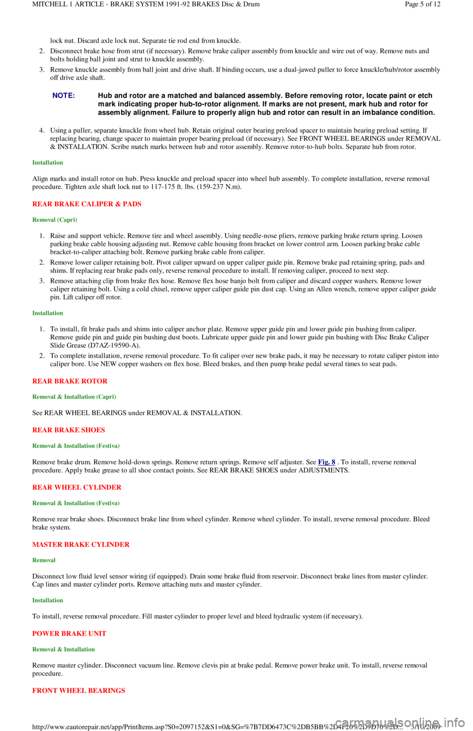
FRONT WHEEL BEARINGS NOTE:Hub and rotor are a m atched and balanced assem bly. Before rem oving rotor, locate paint or etch
m ark indicating proper hub-to-rotor alignm ent. If m arks are not present, m ark hub and rotor for
assem bly alignm ent. Failure to properly align hub and rotor can result in an im balance condition.
Page 5 of 12 MITCHELL 1 ARTICLE - BRAKE SYSTEM 1991-92 BRAKES Disc & Drum
3/10/2009 http://www.eautorepair.net/app/PrintItems.asp?S0=2097152&S1=0&SG=%7B7DD6473C%2DB5BB%2D4F20%2D9D70%2D
...
Page 65 of 454
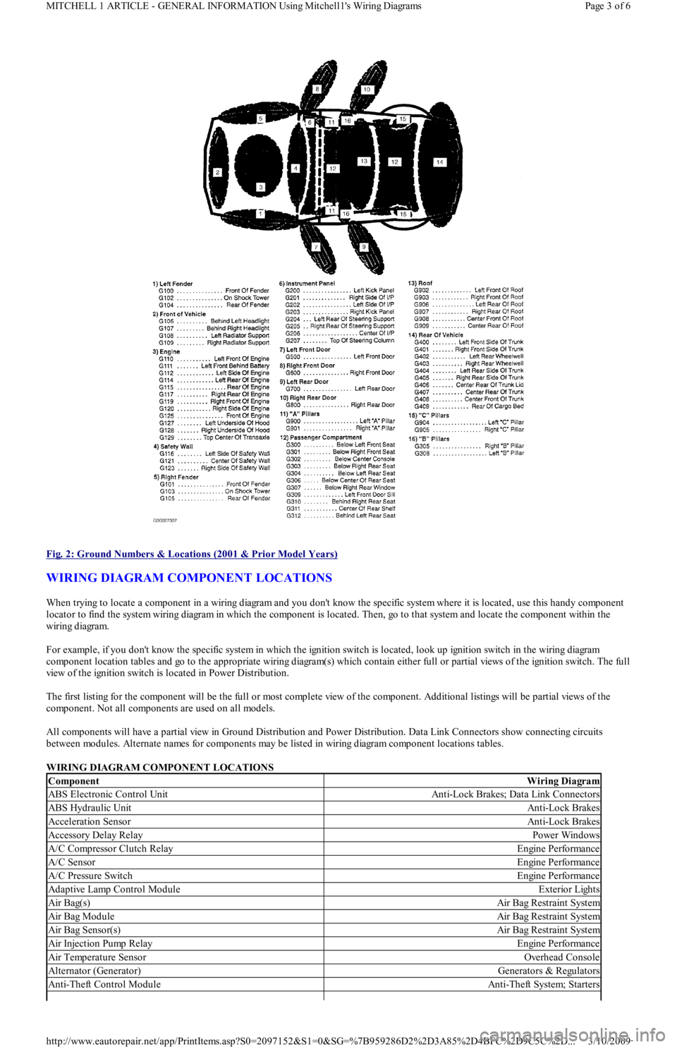
Fig. 2: Ground Numbers & Locations (2001 & Prior Model Years)
WIRING DIAGRAM COMPONENT LOCATIONS
When trying to locate a component in a wiring diagram and you don't know the specific system where it is located, use this handy component
locator to find the system wiring diagram in which the component is located. Then, go to that system and locate the component within the
wiring diagram.
For example, if you don't know the specific system in which the ignition switch is located, look up ignition switch in the wiring diagram
component location tables and go to the appropriate wiring diagram(s) which contain either full or partial views of the ignition switch. The full
view of the ignition switch is located in Power Distribution.
The first listing for the component will be the full or most complete view of the component. Additional listings will be partial views of the
component. Not all components are used on all models.
All components will have a partial view in Ground Distribution and Power Distribution. Data Link Connectors show connecting circuits
between modules. Alternate names for components may be listed in wiring diagram component locations tables.
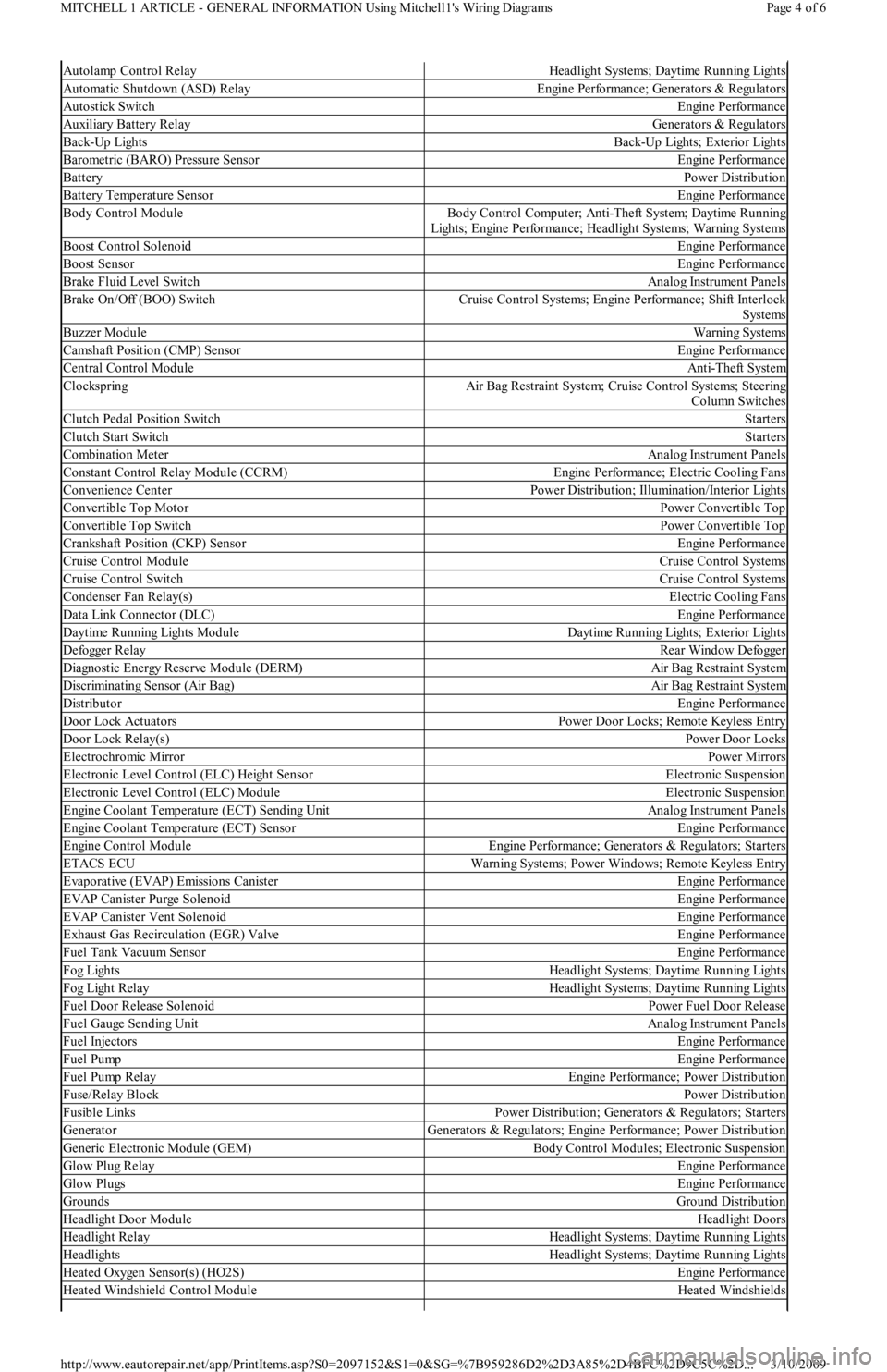
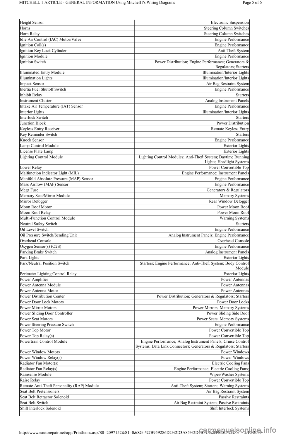
WIRING DIAGRAM COMPONENT LOCATIONS
ComponentWiring Diagram
ABS Electronic Control UnitAnti-Lock Brakes; Data Link Connectors
ABS Hydraulic UnitAnti-Lock Brakes
Acceleration SensorAnti-Lock Brakes
Accessory Delay RelayPower Windows
A/C Compressor Clutch RelayEngine Performance
A/C SensorEngine Performance
A/C Pressure SwitchEngine Performance
Adaptive Lamp Control ModuleExterior Lights
Air Bag(s)Air Bag Restraint System
Air Bag ModuleAir Bag Restraint System
Air Bag Sensor(s)Air Bag Restraint System
Air Injection Pump RelayEngine Performance
Air Temperature SensorOverhead Console
Alternator (Generator)Generators & Regulators
Anti-Theft Control ModuleAnti-Theft System; Starters
Page 3 of 6 MITCHELL 1 ARTICLE - GENERAL INFORMATION Using Mitchell1's Wiring Diagrams
3/10/2009 http://www.eautorepair.net/app/PrintItems.asp?S0=2097152&S1=0&SG=%7B959286D2%2D3A85%2D4BFC%2D9C5C%2D
...
Page 66 of 454
Autolamp Control RelayHeadlight Systems; Daytime Running Lights
Automatic Shutdown (ASD) RelayEngine Performance; Generators & Regulators
Autostick SwitchEngine Performance
Auxiliary Battery RelayGenerators & Regulators
Back-Up LightsBack-Up Lights; Exterior Lights
Barometric (BARO) Pressure SensorEngine Performance
BatteryPower Distribution
Battery Temperature SensorEngine Performance
Body Control ModuleBody Control Computer; Anti-Theft System; Daytime Running
Lights; Engine Performance; Headlight Systems; Warning Systems
Boost Control SolenoidEngine Performance
Boost SensorEngine Performance
Brake Fluid Level SwitchAnalog Instrument Panels
Brake On/Off (BOO) SwitchCruise Control Systems; Engine Performance; Shift Interlock
Systems
Buzzer ModuleWarning Systems
Camshaft Position (CMP) SensorEngine Performance
Central Control ModuleAnti-Theft System
ClockspringAir Bag Restraint System; Cruise Control Systems; Steering
Column Switches
Clutch Pedal Position SwitchStarters
Clutch Start SwitchStarters
Combination MeterAnalog Instrument Panels
Constant Control Relay Module (CCRM)Engine Performance; Electric Cooling Fans
Convenience CenterPower Distribution; Illumination/Interior Lights
Convertible Top MotorPower Convertible Top
Convertible Top SwitchPower Convertible Top
Crankshaft Position (CKP) SensorEngine Performance
Cruise Control ModuleCruise Control Systems
Cruise Control SwitchCruise Control Systems
Condenser Fan Relay(s)Electric Cooling Fans
Data Link Connector (DLC)Engine Performance
Da yt ime R u n n in g Ligh t s M o d u l eDaytime Running Lights; Exterior Lights
Defogger RelayRear Window Defogger
Diagnostic Energy Reserve Module (DERM)Air Bag Restraint System
Discriminating Sensor (Air Bag)Air Bag Restraint System
DistributorEngine Performance
Door Lock ActuatorsPower Door Locks; Remote Keyless Entry
Door Lock Relay(s)Power Door Locks
Electrochromic MirrorPower Mirrors
Electronic Level Control (ELC) Height SensorElectronic Suspension
Electronic Level Control (ELC) ModuleElectronic Suspension
Engine Coolant Temperature (ECT) Sending UnitAnalog Instrument Panels
Engine Coolant Temperature (ECT) SensorEngine Performance
Engine Control ModuleEngine Performance; Generators & Regulators; Starters
ETACS ECUWarning Systems; Power Windows; Remote Keyless Entry
Evaporative (EVAP) Emissions CanisterEngine Performance
EVAP Canister Purge SolenoidEngine Performance
EVAP Canister Vent SolenoidEngine Performance
Exhaust Gas Recirculation (EGR) ValveEngine Performance
Fuel Tank Vacuum SensorEngine Performance
F o g Ligh t sHeadlight Systems; Daytime Running Lights
F o g Ligh t R e l a yHeadlight Systems; Daytime Running Lights
Fuel Door Release SolenoidPower Fuel Door Release
Fuel Gauge Sending UnitAnalog Instrument Panels
Fuel InjectorsEngine Performance
Fuel PumpEngine Performance
Fuel Pump RelayEngine Performance; Power Distribution
Fuse/Relay BlockPower Distribution
Fusible LinksPower Distribution; Generators & Regulators; Starters
GeneratorGenerators & Regulators; Engine Performance; Power Distribution
Generic Electronic Module (GEM)Body Control Modules; Electronic Suspension
Glow Plug RelayEngine Performance
Glow PlugsEngine Performance
GroundsGround Distribution
Headlight Door ModuleHeadlight Doors
Headlight RelayHeadlight Systems; Daytime Running Lights
HeadlightsHeadlight Systems; Daytime Running Lights
Heated Oxygen Sensor(s) (HO2S)Engine Performance
Heated Windshield Control ModuleHeated Windshields
Page 4 of 6 MITCHELL 1 ARTICLE - GENERAL INFORMATION Using Mitchell1's Wiring Diagrams
3/10/2009 http://www.eautorepair.net/app/PrintItems.asp?S0=2097152&S1=0&SG=%7B959286D2%2D3A85%2D4BFC%2D9C5C%2D
...
Page 67 of 454
Height SensorElectronic Suspension
HornsSteering Column Switches
Horn RelaySteering Column Switches
Idle Air Control (IAC) Motor/ValveEngine Performance
Ignition Coil(s)Engine Performance
Ignition Key Lock CylinderAnti-Theft System
Ignition ModuleEngine Performance
Ignition SwitchPower Distribution; Engine Performance; Generators &
Regulators; Starters
Illuminated Entry ModuleIllumination/Interior Lights
Illumination LightsIllumination/Interior Lights
Impact SensorAir Bag Restraint System
Inertia Fuel Shutoff SwitchEngine Performance
In h ib it Rel ayStarters
Instrument ClusterAnalog Instrument Panels
Intake Air Temperature (IAT) SensorEngine Performance
Interior LightsIllumination/Interior Lights
In t erl o ck Swit chStarters
Junction BlockPower Distribution
Keyless Entry ReceiverRemote Keyless Entry
Key Reminder SwitchStarters
Knock SensorEngine Performance
Lamp Control ModuleExterior Lights
License Plate LampExterior Lights
Lighting Control ModuleLighting Control Modules; Anti-Theft System; Daytime Running
Lights; Headlight Systems
Lower RelayPower Convertible Top
Malfunction Indicator Light (MIL)Engine Performance; Instrument Panels
Manifold Absolute Pressure (MAP) SensorEngine Performance
Mass Airflow (MAF) SensorEngine Performance
Mega FuseGenerators & Regulators
Memory Seat/Mirror ModuleMemory Systems
M ir r o r De fo gge rRear Window Defogger
Moon Roof MotorPower Moon Roof
Moon Roof RelayPower Moon Roof
Multi-Function Control ModuleWarning Systems
Neutral Safety SwitchStarters
Oil Level SwitchEngine Performance
Oil Pressure Switch/Sending UnitAnalog Instrument Panels; Engine Performance
Overhead ConsoleOverhead Console
Oxygen Sensor(s) (O2S)Engine Performance
Parking Brake SwitchAnalog Instrument Panels
Park LightsExterior Lights
Park/Neutral Position SwitchStarters; Engine Performance; Anti-Theft System; Body Control
Module
Perimeter Lighting Control RelayExterior Lights
Power AmplifierPower Antennas
Power Antenna ModulePower Antennas
Power Antenna MotorPower Antennas
Power Distribution CenterPower Distribution; Generators & Regulators; Starters
Power Door Lock MotorsPower Door Locks
Power Mirror MotorsPower Mirrors; Memory Systems
Power Sliding Door ControllerPower Sliding Side Door
Power Seat MotorsPower Seats; Memory Systems
Power Steering Pressure SwitchEngine Performance
Power Top MotorPower Convertible Top
Power Top Relay(s)Power Convertible Top
Powertrain Control ModuleEngine Performance; Analog Instrument Panels; Cruise Control
Systems; Data Link Connectors; Generators & Regulators; Starters
Power Window MotorsPower Windows
Power Window Relay(s)Power Windows
Radiator Fan Motor(s)Electric Cooling Fans
Radiator Fan Relay(s)Engine Performance; Electric Cooling Fans;
Rainsense ModuleWiper/Washer Systems
Raise RelayPower Convertible Top
Remote Anti-Theft Personality (RAP) ModuleAnti-Theft System; Starters; Warning Systems
Seat Belt PretensionersAir Bag Restraint System
Seat Belt Retractor SolenoidPassive Restraints
Seat Belt SwitchAir Bag Restraint System; Passive Restraints
Shift Interlock SolenoidShift Interlock Systems
Page 5 of 6 MITCHELL 1 ARTICLE - GENERAL INFORMATION Using Mitchell1's Wiring Diagrams
3/10/2009 http://www.eautorepair.net/app/PrintItems.asp?S0=2097152&S1=0&SG=%7B959286D2%2D3A85%2D4BFC%2D9C5C%2D
...
Page 68 of 454
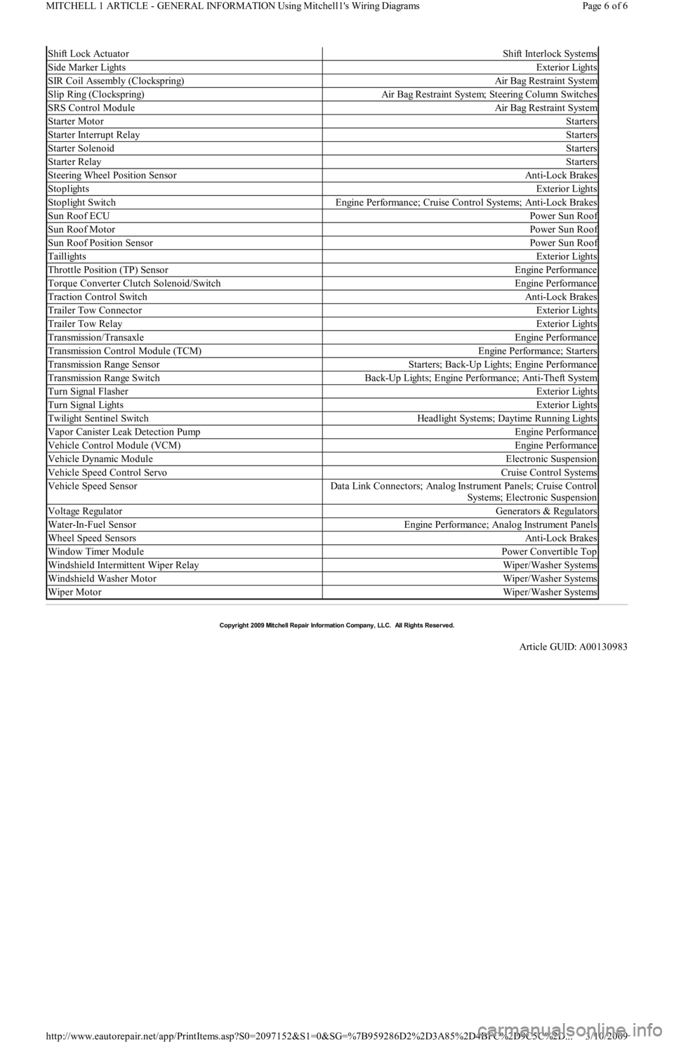
Shift Lock ActuatorShift Interlock Systems
Side Marker LightsExterior Lights
SIR Coil Assembly (Clockspring)Air Bag Restraint System
Slip Ring (Clockspring)Air Bag Restraint System; Steering Column Switches
SRS Control ModuleAir Bag Restraint System
Starter MotorStarters
Starter Interrupt RelayStarters
Starter SolenoidStarters
Starter RelayStarters
Steering Wheel Position SensorAnti-Lock Brakes
StoplightsExterior Lights
Stoplight SwitchEngine Performance; Cruise Control Systems; Anti-Lock Brakes
Sun Roof ECUPower Sun Roof
Sun Roof MotorPower Sun Roof
Sun Roof Position SensorPower Sun Roof
TaillightsExterior Lights
Throttle Position (TP) SensorEngine Performance
Torque Converter Clutch Solenoid/SwitchEngine Performance
Traction Control SwitchAnti-Lock Brakes
Trailer Tow ConnectorExterior Lights
Trailer Tow RelayExterior Lights
Transmission/TransaxleEngine Performance
Transmission Control Module (TCM)Engine Performance; Starters
Transmission Range SensorStarters; Back-Up Lights; Engine Performance
Transmission Range SwitchBack-Up Lights; Engine Performance; Anti-Theft System
Turn Signal FlasherExterior Lights
Tu r n S ign a l Ligh t sExterior Lights
Twilight Sentinel SwitchHeadlight Systems; Daytime Running Lights
Vapor Canister Leak Detection PumpEngine Performance
Vehicle Control Module (VCM)Engine Performance
Vehicle Dynamic ModuleElectronic Suspension
Vehicle Speed Control ServoCruise Control Systems
Vehicle Speed SensorData Link Connectors; Analog Instrument Panels; Cruise Control
Systems; Electronic Suspension
Voltage RegulatorGenerators & Regulators
Water-In-Fuel SensorEngine Performance; Analog Instrument Panels
Wheel Speed SensorsAnti-Lock Brakes
Window Timer ModulePower Convertible Top
Windshield Intermittent Wiper RelayWiper/Washer Systems
Windshield Washer MotorWiper/Washer Systems
Wiper MotorWiper/Washer Systems
Copyr ight 2009 Mitchell Repair Information Company, LLC. All Rights Reserved.
Article GUID: A00130983
Page 6 of 6 MITCHELL 1 ARTICLE - GENERAL INFORMATION Using Mitchell1's Wiring Diagrams
3/10/2009 http://www.eautorepair.net/app/PrintItems.asp?S0=2097152&S1=0&SG=%7B959286D2%2D3A85%2D4BFC%2D9C5C%2D
...
Page 102 of 454
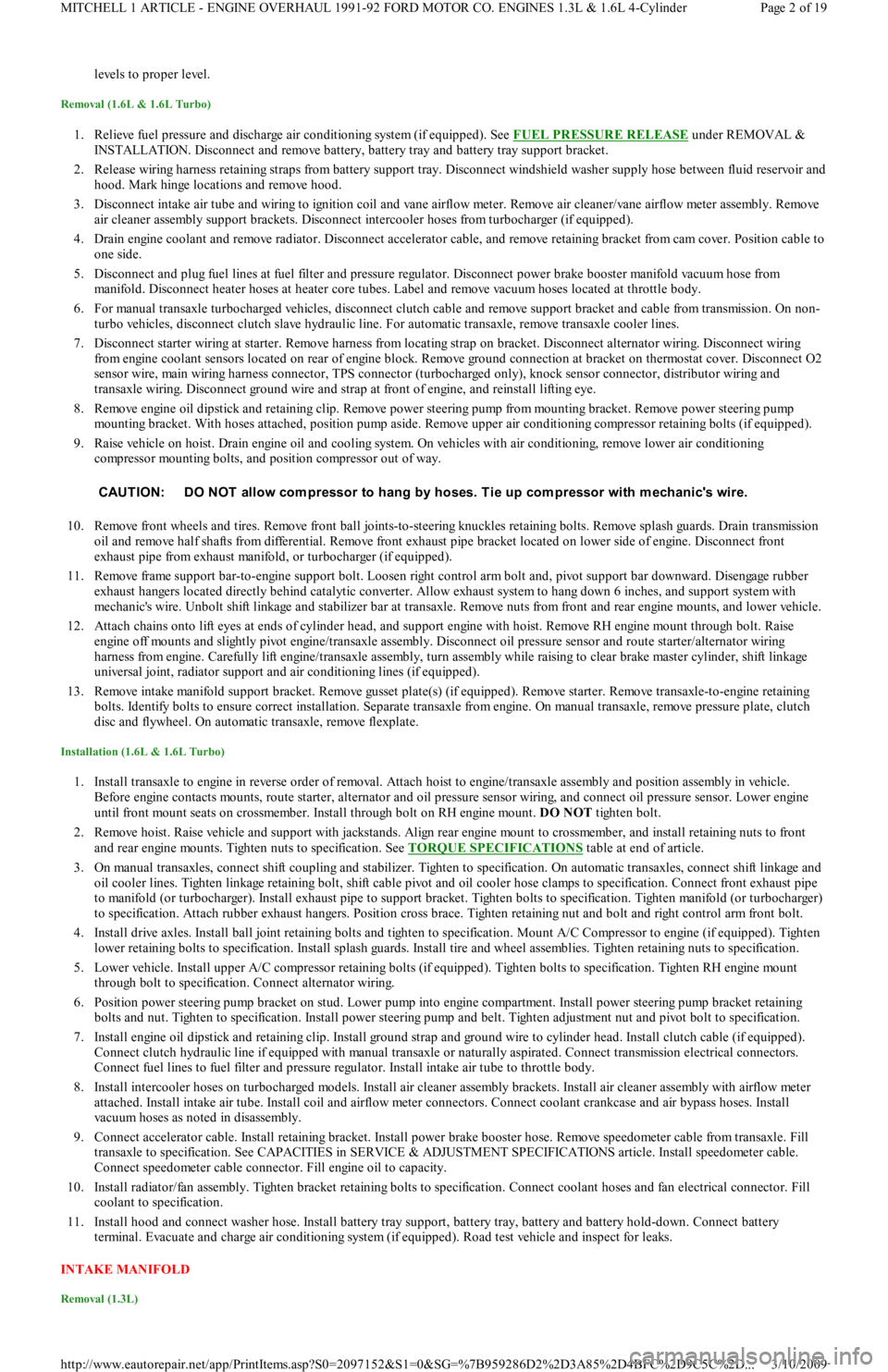
levels to proper level.
Removal (1.6L & 1.6L Turbo)
1. Relieve fuel pressure and discharge air conditioning system (if equipped). See FUEL PRESSURE RELEASE under REMOVAL &
INSTALLATION. Disconnect and remove battery, battery tray and battery tray support bracket.
2. Release wiring harness retaining straps from battery support tray. Disconnect windshield washer supply hose between fluid reservoir and
hood. Mark hinge locations and remove hood.
3. Disconnect intake air tube and wiring to ignition coil and vane airflow meter. Remove air cleaner/vane airflow meter assembly. Remove
air cleaner assembly support brackets. Disconnect intercooler hoses from turbocharger (if equipped).
4. Drain engine coolant and remove radiator. Disconnect accelerator cable, and remove retaining bracket from cam cover. Position cable to
one side.
5. Disconnect and plug fuel lines at fuel filter and pressure regulator. Disconnect power brake booster manifold vacuum hose from
manifold. Disconnect heater hoses at heater core tubes. Label and remove vacuum hoses located at throttle body.
6. For manual transaxle turbocharged vehicles, disconnect clutch cable and remove support bracket and cable from transmission. On non-
turbo vehicles, disconnect clutch slave hydraulic line. For automatic transaxle, remove transaxle cooler lines.
7. Disconnect starter wiring at starter. Remove harness from locating strap on bracket. Disconnect alternator wiring. Disconnect wiring
from engine coolant sensors located on rear of engine block. Remove ground connection at bracket on thermostat cover. Disconnect O2
sensor wire, main wiring harness connector, TPS connector (turbocharged only), knock sensor connector, distributor wiring and
transaxle wiring. Disconnect ground wire and strap at front of engine, and reinstall lifting eye.
8. Remove engine oil dipstick and retaining clip. Remove power steering pump from mounting bracket. Remove power steering pump
mounting bracket. With hoses attached, position pump aside. Remove upper air conditioning compressor retaining bolts (if equipped).
9. Raise vehicle on hoist. Drain engine oil and cooling system. On vehicles with air conditioning, remove lower air conditioning
compressor mounting bolts, and position compressor out of way.
10. Remove front wheels and tires. Remove front ball joints-to-ste e r in g kn u c kl e s r e t a in in g b o l t s. R e mo ve sp l a sh gu a r d s. Dr a in t ransmission
oil and remove half shafts from differential. Remove front exhaust pipe bracket located on lower side of engine. Disconnect front
exhaust pipe from exhaust manifold, or turbocharger (if equipped).
11. Remove frame support bar-to-engine support bolt. Loosen right control arm bolt and, pivot support bar downward. Disengage rubber
exhaust hangers located directly behind catalytic converter. Allow exhaust system to hang down 6 inches, and support system with
mechanic's wire. Unbolt shift linkage and stabilizer bar at transaxle. Remove nuts from front and rear engine mounts, and lower vehicle.
12. Attach chains onto lift eyes at ends of cylinder head, and support engine with hoist. Remove RH engine mount through bolt. Raise
engine off mounts and slightly pivot engine/transaxle assembly. Disconnect oil pressure sensor and route starter/alternator wiring
harness from engine. Carefully lift engine/transaxle assembly, turn assembly while raising to clear brake master cylinder, shift linkage
universal joint, radiator support and air conditioning lines (if equipped).
13. Remove intake manifold support bracket. Remove gusset plate(s) (if equipped). Remove starter. Remove transaxle-to-engine retaining
bolts. Identify bolts to ensure correct installation. Separate transaxle from engine. On manual transaxle, remove pressure plate, clutch
disc and flywheel. On automatic transaxle, remove flexplate.
Installation (1.6L & 1.6L Turbo)
1. Install transaxle to engine in reverse order of removal. Attach hoist to engine/transaxle assembly and position assembly in vehicle.
Before engine contacts mounts, route starter, alternator and oil pressure sensor wiring, and connect oil pressure sensor. Lower engine
until front mount seats on crossmember. Install through bolt on RH engine mount. DO NOT tighten bolt.
2. Remove hoist. Raise vehicle and support with jackstands. Align rear engine mount to crossmember, and install retaining nuts to front
and rear engine mounts. Tighten nuts to specification. See TORQUE SPECIFICATIONS
table at end of article.
3. On manual transaxles, connect shift coupling and stabilizer. Tighten to specification. On automatic transaxles, connect shift linkage and
oil cooler lines. Tighten linkage retaining bolt, shift cable pivot and oil cooler hose clamps to specification. Connect front exhaust pipe
to manifold (or turbocharger). Install exhaust pipe to support bracket. Tighten bolts to specification. Tighten manifold (or turbocharger)
to specification. Attach rubber exhaust hangers. Position cross brace. Tighten retaining nut and bolt and right control arm front bolt.
4. Install drive axles. Install ball joint retaining bolts and tighten to specification. Mount A/C Compressor to engine (if equipped). Tighten
lower retaining bolts to specification. Install splash guards. Install tire and wheel assemblies. Tighten retaining nuts to specification.
5. Lower vehicle. Install upper A/C compressor retaining bolts (if equipped). Tighten bolts to specification. Tighten RH engine mo u n t
through bolt to specification. Connect alternator wiring.
6. Position power steering pump bracket on stud. Lower pump into engine compartment. Install power steering pump bracket retaining
bolts and nut. Tighten to specification. Install power steering pump and belt. Tighten adjustment nut and pivot bolt to specification.
7. Install engine oil dipstick and retaining clip. Install ground strap and ground wire to cylinder head. Install clutch cable (if equipped).
Connect clutch hydraulic line if equipped with manual transaxle or naturally aspirated. Connect transmission electrical connectors.
Connect fuel lines to fuel filter and pressure regulator. Install intake air tube to throttle body.
8. Install intercooler hoses on turbocharged models. Install air cleaner assembly brackets. Install air cleaner assembly with airflow meter
attached. Install intake air tube. Install coil and airflow meter connectors. Connect coolant crankcase and air bypass hoses. Install
vacuum hoses as noted in disassembly.
9. Connect accelerator cable. Install retaining bracket. Install power brake booster hose. Remove speedometer cable from transaxle. Fill
transaxle to specification. See CAPACITIES in SERVICE & ADJUSTMENT SPECIFICATIONS article. Install speedometer cable.
Connect speedometer cable connector. Fill engine oil to capacity.
10. Install radiator/fan assembly. Tighten bracket retaining bolts to specification. Connect coolant hoses and fan electrical connector. Fill
coolant to specification.
11. Install hood and connect washer hose. Install battery tray support, battery tray, battery and battery hold-down. Connect battery
terminal. Evacuate and charge air conditioning system (if equipped). Road test vehicle and inspect for leaks.
INTAKE MANIFOLD
Removal (1.3L)
CAUT ION: DO NOT allow com pressor to hang by hoses. T ie up com pressor with m echanic's wire.
Page 2 of 19 MITCHELL 1 ARTICLE - ENGINE OVERHAUL 1991-92 FORD MOTOR CO. ENGINES 1.3L & 1.6L 4-Cylinder
3/10/2009 http://www.eautorepair.net/app/PrintItems.asp?S0=2097152&S1=0&SG=%7B959286D2%2D3A85%2D4BFC%2D9C5C%2D
...
Page 130 of 454
IDLE SPEED & MIXTURE
IDLE MIXTURE
IDLE SPEED
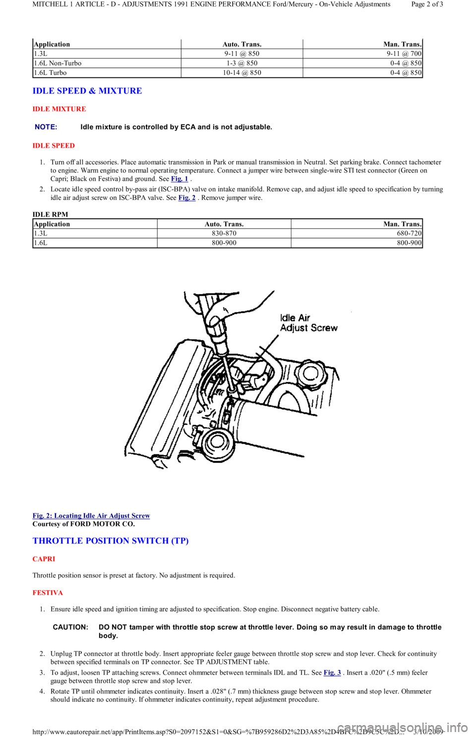
1. Turn off all accessories. Place automatic transmission in Park or manual transmission in Neutral. Set parking brake. Connect tachometer
to engine. Warm engine to normal operating temperature. Connect a jumper wire between single-wire STI test connector (Green on
Capri; Black on Festiva) and ground. See Fig. 1
.
2. Locate idle speed control by-pass air (ISC-BPA) valve on intake manifold. Remove cap, and adjust idle speed to specification by turning
idle air adjust screw on ISC-BPA valve. See Fig. 2
. Remove jumper wire.
IDLE RPM
Fig. 2: Locating Idle Air Adjust Screw
Courtesy of FORD MOTOR CO.
THROTTLE POSITION SWITCH (TP)
CAPRI
Throttle position sensor is preset at factory. No adjustment is required.
FESTIVA
1. Ensure idle speed and ignition timing are adjusted to specification. Stop engine. Disconnect negative battery cable.
2. Unplug TP connector at throttle body. Insert appropriate feeler gauge between throttle stop screw and stop lever. Check for continuity
between specified terminals on TP connector. See TP ADJUSTMENT table.
3. To adjust, loosen TP attaching screws. Connect ohmmeter between terminals IDL and TL. See Fig. 3
. Insert a .020" (.5 mm) feeler
gauge between throttle stop screw and stop lever.
4. Rotate TP until ohmmeter indicates continuity. Insert a .028" (.7 mm) thickness gauge between stop screw and stop lever. Ohmmeter
should indicate no continuity. If ohmmeter indicates continuity, repeat adjustment procedure.
ApplicationAuto. Trans.Man. Trans.
1.3L9-11 @ 8509-11 @ 700
1.6L Non-Turbo1-3 @ 8500-4 @ 850
1.6L Turbo10-14 @ 8500-4 @ 850
NOTE:Idle m ixture is controlled by ECA and is not adjustable.
ApplicationAuto. Trans.Man. Trans.
1.3L830-870680-720
1.6L800-900800-900
CAUT ION: DO NOT tam per with throttle stop screw at throttle lever. Doing so m ay result in dam age to throttle
body.
Page 2 of 3 MITCHELL 1 ARTICLE - D - ADJUSTMENTS 1991 ENGINE PERFORMANCE Ford/Mercury - On-Vehicle Adjustments
3/10/2009 http://www.eautorepair.net/app/PrintItems.asp?S0=2097152&S1=0&SG=%7B959286D2%2D3A85%2D4BFC%2D9C5C%2D
...
Page 162 of 454
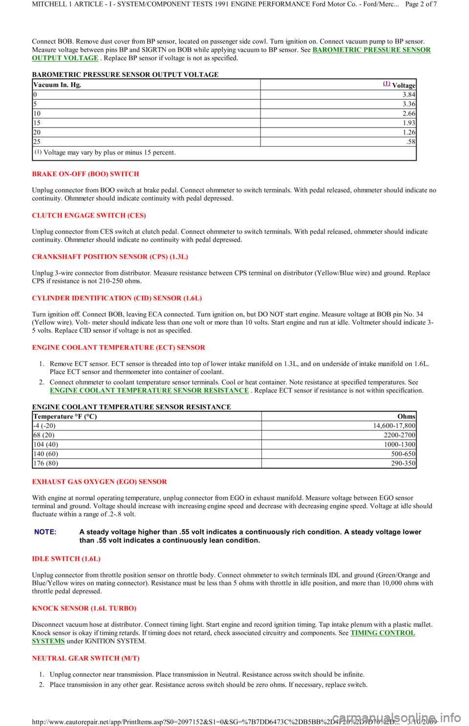
Connect BOB. Remove dust cover from BP sensor, located on passenger side cowl. Turn ignition on. Connect vacuum pump to BP sensor.
Measure voltage between pins BP and SIGRTN on BOB while applying vacuum to BP sensor. See BAROMETRIC PRESSURE SENSOR
OUTPUT VOLTAGE . Replace BP sensor if voltage is not as specified.
BAROMETRIC PRESSURE SENSOR OUTPUT VOLTAGE
BRAKE ON-OFF (BOO) SWITCH
Unplug connector from BOO switch at brake pedal. Connect ohmmeter to switch terminals. With pedal released, ohmmeter should indicate no
continuity. Ohmmeter should indicate continuity with pedal depressed.
CLUTCH ENGAGE SWITCH (CES)
Unplug connector from CES switch at clutch pedal. Connect ohmmeter to switch terminals. With pedal released, ohmmeter should indicate
continuity. Ohmmeter should indicate no continuity with pedal depressed.
CRANKSHAFT POSITION SENSOR (CPS) (1.3L)
Unplug 3-wire connector from distributor. Measure resistance between CPS terminal on distributor (Yellow/Blue wire) and ground. Replace
CPS if resistance is not 210-250 ohms.
CYLINDER IDENTIFICATION (CID) SENSOR (1.6L)
Turn ignition off. Connect BOB, leaving ECA connected. Turn ignition on, but DO NOT start engine. Measure voltage at BOB pin No. 34
(Yellow wire). Volt- meter should indicate less than one volt or more than 10 volts. Start engine and run at idle. Voltmeter should indicate 3-
5 volts. Replace CID sensor if voltage is not as specified.
ENGINE COOLANT TEMPERATURE (ECT) SENSOR
1. Remove ECT sensor. ECT sensor is threaded into top of lower intake manifold on 1.3L, and on underside of intake manifold on 1.6L.
Place ECT sensor and thermometer into container of coolant.
2. Connect ohmmeter to coolant temperature sensor terminals. Cool or heat container. Note resistance at specified temperatures. See
ENGINE COOLANT TEMPERATURE SENSOR RESISTANCE
. Replace ECT sensor if resistance is not within specification.
ENGINE COOLANT TEMPERATURE SENSOR RESISTANCE
EXHAUST GAS OXYGEN (EGO) SENSOR
With engine at normal operating temperature, unplug connector from EGO in exhaust manifold. Measure voltage between EGO sensor
terminal and ground. Voltage should increase with increasing engine speed and decrease with decreasing engine speed. Voltage at idle should
fluctuate within a range of .2-.8 volt.
IDLE SW ITCH (1.6L)
Unplug connector from throttle position sensor on throttle body. Connect ohmmeter to switch terminals IDL and ground (Green/Orange and
Blue/Yellow wires on mating connector). Resistance must be less than 5 ohms with throttle in idle position, and more than 10,000 ohms with
throttle pedal depressed.
KNOCK SENSOR (1.6L TURBO)
Disconnect vacuum hose at distributor. Connect timing light. Start engine and record ignition timing. Tap intake plenum with a plastic mallet.
Knock sensor is okay if timing retards. If timing does not retard, check associated circuitry and components. See TIMING CONTROL
SYSTEMS under IGNITION SYSTEM.
NEUTRAL GEAR SWITCH (M/T)
1. Unplug connector near transmission. Place transmission in Neutral. Resistance across switch should be infinite.
2. Place transmission in any other gear. Resistance across switch should be zero ohms. If necessary, replace switch.
Vacuum In. Hg.(1) Voltage
03.84
53.36
102.66
151.93
201.26
25.58
(1)Voltage may vary by plus or minus 15 percent.
Temperature °F (°C)Ohms
-4 (-20)14,600-17,800
68 (20)2200-2700
104 (40)1000-1300
140 (60)500-650
176 (80)290-350
NOTE:A steady voltage higher than .55 volt indicates a continuously rich condition. A steady voltage lower
than .55 volt indicates a continuously lean condition.
Page 2 of 7 MITCHELL 1 ARTICLE - I - SYSTEM/COMPONENT TESTS 1991 ENGINE PERFORMANCE Ford Motor Co. - Ford/Merc
...
3/10/2009 http://www.eautorepair.net/app/PrintItems.asp?S0=2097152&S1=0&SG=%7B7DD6473C%2DB5BB%2D4F20%2D9D70%2D
...
Page 169 of 454
memory. Intermittent failures may be caused by a sensor, connector, or wiring. See INTERMITTENTS in TESTS W/O CODES article in the
ENGINE PERFORMANCE Section.
VISUAL CHECK & VEHICLE PREPARATION
Before connecting any equipment to diagnose EEC system, perform following preparatory procedures:
Verify condition of air cleaner and air ducts.
Check all vacuum hoses for leaks, restrictions, or improper routing.
Check EEC system wiring harness electrical connections for corrosion, bent or broken pins, loose wires or terminals, or improper
routing.
Check ECA, sensors, and actuators for physical damage.
Check engine oil and coolant level.
Perform all necessary safety precautions to prevent personal injury or vehicle damage.
Set parking brake. Place shift lever in Park for automatic transmissions, or Neutral for manual transmissions. DO NOT move shift lever
during test unless specifically directed.
Turn off all lights and accessories. Ensure vehicle doors are closed when measuring voltage or resistance.
Start engine. Run at idle until upper radiator hose is hot and pressurized and engine is off fast idle. Check for leaks around exhaust
manifold, exhaust gas oxygen sensor, and vacuum hose connections.
Turn ignition off. Service items as required. Go to EQUIPMENT HOOK-UP .
EQUIPMENT HOOK-UP
VOM
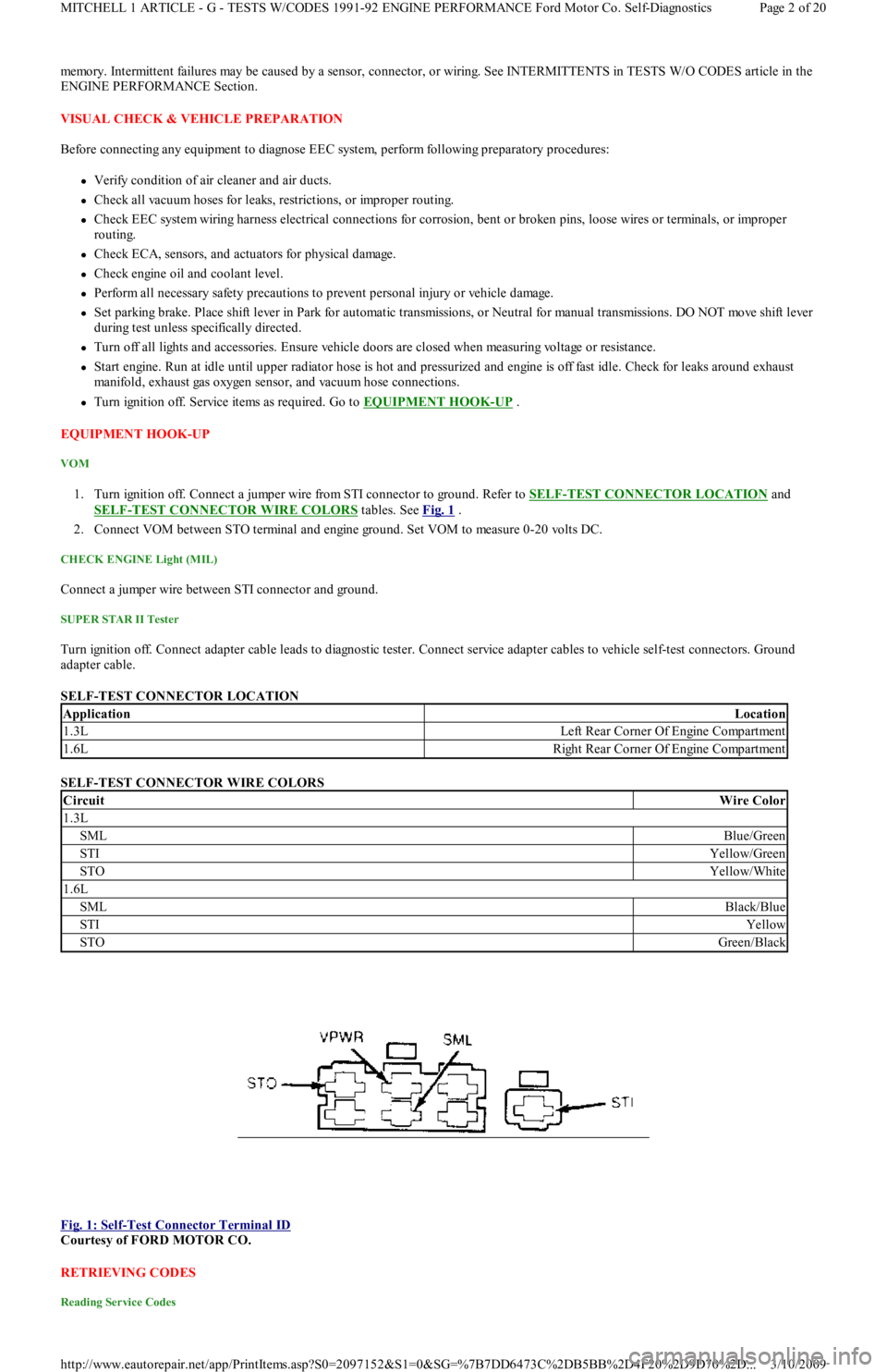
1. Turn ignition off. Connect a jumper wire from STI connector to ground. Refer to SELF-TEST CONNECTOR LOCATION and
SELF
-TEST CONNECTOR WIRE COLORS tables. See Fig. 1 .
2. Connect VOM between STO terminal and engine ground. Set VOM to measure 0-20 volts DC.
CHECK ENGINE Light (MIL)
Connect a jumper wire between STI connector and ground.
SUPER STAR II Tester
Turn ignition off. Connect adapter cable leads to diagnostic tester. Connect service adapter cables to vehicle self-test connectors. Ground
adapter cable.
SELF-TEST CONNECTOR LOCATION
SELF-TEST CONNECTOR WIRE COLORS
Fig. 1: Self
-Test Connector Terminal ID
Courtesy of FORD MOTOR CO.
RETRIEVING CODES
Reading Service Codes
ApplicationLocation
1.3LLeft Rear Corner Of Engine Compartment
1.6LRight Rear Corner Of Engine Compartment
CircuitWire Color
1.3L
SMLBlue/Green
STIYellow/Green
STOYellow/White
1.6L
SMLBlack/Blue
STIYellow
STOGreen/Black
Page 2 of 20 MITCHELL 1 ARTICLE - G - TESTS W/CODES 1991-92 ENGINE PERFORMANCE Ford Motor Co. Self-Diagnostics
3/10/2009 http://www.eautorepair.net/app/PrintItems.asp?S0=2097152&S1=0&SG=%7B7DD6473C%2DB5BB%2D4F20%2D9D70%2D
...
Page 170 of 454
Engine control system communicates malfunctions to technician through service codes. These service codes are 2-digit numbers representing a
particular defect. Service codes are transmitted through STO connector.
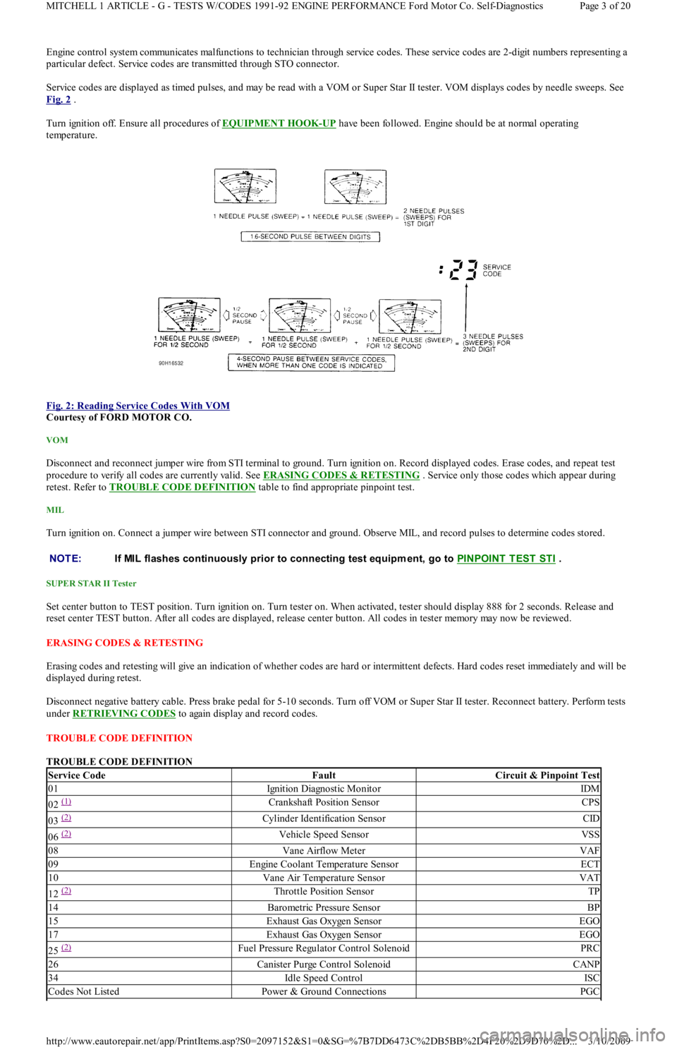
Service codes are displayed as timed pulses, and may be read with a VOM or Super Star II tester. VOM displays codes by needle sweeps. See
Fig. 2
.
Turn ignition off. Ensure all procedures of EQUIPMENT HOOK
-UP have been followed. Engine should be at normal operating
temperature.
Fig. 2: Reading Service Codes With VOM
Courtesy of FORD MOTOR CO.
VOM
Disconnect and reconnect jumper wire from STI terminal to ground. Turn ignition on. Record displayed codes. Erase codes, and repeat test
procedure to verify all codes are currently valid. See ERASING CODES & RETESTING . Service only those codes which appear during
retest. Refer to TROUBLE CODE DEFINITION
table to find appropriate pinpoint test.
MIL
Turn ignition on. Connect a jumper wire between STI connector and ground. Observe MIL, and record pulses to determine codes stored.
SUPER STAR II Tester
Set center button to TEST position. Turn ignition on. Turn tester on. When activated, tester should display 888 for 2 seconds. Release and
reset center TEST button. After all codes are displayed, release center button. All codes in tester memory may now be reviewed.
ERASING CODES & RETESTING
Erasing codes and retesting will give an indication of whether codes are hard or intermittent defects. Hard codes reset immediately and will be
displayed during retest.
Disconnect negative battery cable. Press brake pedal for 5-10 seconds. Turn off VOM or Super Star II tester. Reconnect battery. Perform tests
under RETRIEVING CODES
to again display and record codes.
TROUBLE CODE DEFINITION
TROUBLE CODE DEFINITION
NOTE:If MIL flashes continuously prior to connecting test equipm ent, go to PINPOINT T EST ST I .
Service CodeFaultCircuit & Pinpoint Test
01Ignition Diagnostic MonitorIDM
02 (1) Crankshaft Position SensorCPS
03 (2) Cylinder Identification SensorCID
06 (2) Vehicle Speed SensorVSS
08Vane Airflow MeterVAF
09Engine Coolant Temperature SensorECT
10Vane Air Temperature SensorVAT
12 (2) Throttle Position SensorTP
14Barometric Pressure SensorBP
15Exhaust Gas Oxygen SensorEGO
17Exhaust Gas Oxygen SensorEGO
25 (2) Fuel Pressure Regulator Control SolenoidPRC
26Canister Purge Control SolenoidCANP
34Idle Speed ControlISC
Codes Not ListedPower & Ground ConnectionsPGC
Page 3 of 20 MITCHELL 1 ARTICLE - G - TESTS W/CODES 1991-92 ENGINE PERFORMANCE Ford Motor Co. Self-Diagnostics
3/10/2009 http://www.eautorepair.net/app/PrintItems.asp?S0=2097152&S1=0&SG=%7B7DD6473C%2DB5BB%2D4F20%2D9D70%2D
...