low beam FORD FESTIVA 1991 Service Manual
[x] Cancel search | Manufacturer: FORD, Model Year: 1991, Model line: FESTIVA, Model: FORD FESTIVA 1991Pages: 454, PDF Size: 9.53 MB
Page 2 of 454

Back To Article
INST RUMENT PANEL
1991 ACCESSORIES & SAFET Y EQUIPMENT Ford Motor Co. Switches & Instrum ent Panels - Standard
DESCRIPTION & OPERATION
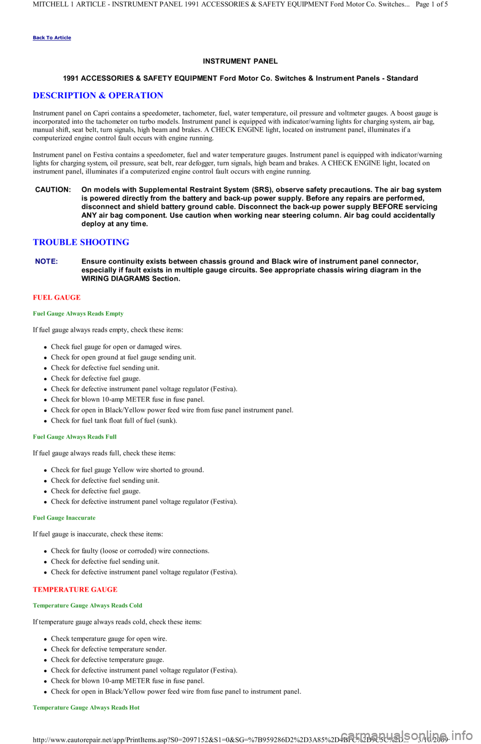
Instrument panel on Capri contains a speedometer, tachometer, fuel, water temperature, oil pressure and voltmeter gauges. A boost gauge is
incorporated into the tachometer on turbo models. Instrument panel is equipped with indicator/warning lights for charging system, air b ag,
manual shift, seat belt, turn signals, high beam and brakes. A CHECK ENGINE light, located on instrument panel, illuminates if a
computerized engine control fault occurs with engine running.
Instrument panel on Festiva contains a speedometer, fuel and water temperature gauges. Instrument panel is equipped with indicator/warning
lights for charging system, oil pressure, seat belt, rear defogger, turn signals, high beam and brakes. A CHECK ENGINE light, located on
instrument panel, illuminates if a computerized engine control fault occurs with engine running.
TROUBLE SHOOTING
FUEL GAUGE
Fuel Gauge Always Reads Empty
If fuel gauge always reads empty, check these items:
Check fuel gauge for open or damaged wires.
Check for open ground at fuel gauge sending unit.
Check for defective fuel sending unit.
Check for defective fuel gauge.
Check for defective instrument panel voltage regulator (Festiva).
Check for blown 10-amp METER fuse in fuse panel.
Check for open in Black/Yellow power feed wire from fuse panel instrument panel.
Check for fuel tank float full of fuel (sunk).
Fuel Gauge Always Reads Full
If fuel gauge always reads full, check these items:
Check for fuel gauge Yellow wire shorted to ground.
Check for defective fuel sending unit.
Check for defective fuel gauge.
Check for defective instrument panel voltage regulator (Festiva).
Fuel Gauge Inaccurate
If fuel gauge is inaccurate, check these items:
Check for faulty (loose or corroded) wire connections.
Check for defective fuel sending unit.
Check for defective instrument panel voltage regulator (Festiva).
TEMPERATURE GAUGE
Temperature Gauge Always Reads Cold
If temperature gauge always reads cold, check these items:
Check temperature gauge for open wire.
Check for defective temperature sender.
Check for defective temperature gauge.
Check for defective instrument panel voltage regulator (Festiva).
Check for blown 10-amp METER fuse in fuse panel.
Check for open in Black/Yellow power feed wire from fuse panel to instrument panel.
Temperature Gauge Always Reads Hot
CAUT ION: On m odels with Supplem ental Restraint System (SRS), observe safety precautions. T he air bag system
is powered directly from the battery and back-up power supply. Before any repairs are perform ed,
disconnect and shield battery ground cable. Disconnect the back-up power supply BEFORE servicing
ANY air bag com ponent. Use caution when working near steering colum n. Air bag could accidentally
deploy at any tim e.
NOTE:Ensure continuity exists between chassis ground and Black wire of instrum ent panel connector,
especially if fault exists in m ultiple gauge circuits. See appropriate chassis wiring diagram in the
WIRING DIAGRAMS Section.
Page 1 of 5 MITCHELL 1 ARTICLE - INSTRUMENT PANEL 1991 ACCESSORIES & SAFETY EQUIPMENT Ford Motor Co. Switches
...
3/10/2009 http://www.eautorepair.net/app/PrintItems.asp?S0=2097152&S1=0&SG=%7B959286D2%2D3A85%2D4BFC%2D9C5C%2D
...
Page 398 of 454

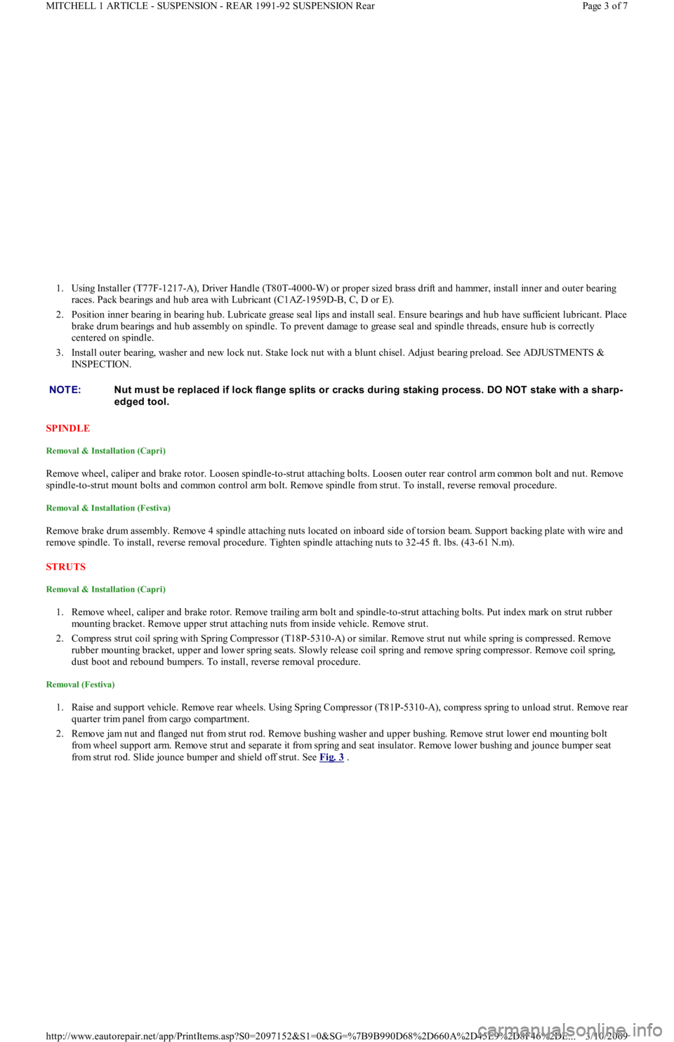
1. Using Installer (T77F-1217-A), Driver Handle (T80T-4000-W) or proper sized brass drift and hammer, install inner and outer bearing
races. Pack bearings and hub area with Lubricant (C1AZ-1959D-B, C, D or E).
2. Position inner bearing in bearing hub. Lubricate grease seal lips and install seal. Ensure bearings and hub have sufficient lubricant. Place
brake drum bearings and hub assembly on spindle. To prevent damage to grease seal and spindle threads, ensure hub is correctly
centered on spindle.
3. Install outer bearing, washer and new lock nut. Stake lock nut with a blunt chisel. Adjust bearing preload. See ADJUSTMENTS &
INSPECTION.
SPINDLE
Removal & Installation (Capri)
Remove wheel, caliper and brake rotor. Loosen spindle-to-strut attaching bolts. Loosen outer rear control arm common bolt and nut. Remove
spindle-to-strut mount bolts and common control arm bolt. Remove spindle from strut. To install, reverse removal procedure.
Removal & Installation (Festiva)
Remove brake drum assembly. Remove 4 spindle attaching nuts located on inboard side of torsion beam. Support backing plate with wire and
remove spindle. To install, reverse removal procedure. Tighten spindle attaching nuts to 32-45 ft. lbs. (43-61 N.m).
STRUTS
Removal & Installation (Capri)
1. Remove wheel, caliper and brake rotor. Remove trailing arm bolt and spindle-to-strut attaching bolts. Put index mark on strut rubber
mounting bracket. Remove upper strut attaching nuts from inside vehicle. Remove strut.
2. Compress strut coil spring with Spring Compressor (T18P-5310-A) or similar. Remove strut nut while spring is compressed. Remove
rubber mounting bracket, upper and lower spring seats. Slowly release coil spring and remove spring compressor. Remove coil spring,
dust boot and rebound bumpers. To install, reverse removal procedure.
Removal (Festiva)
1. Raise and support vehicle. Remove rear wheels. Using Spring Compressor (T81P-5310-A), compress spring to unload strut. Remove rear
quarter trim panel from cargo compartment.
2. Remove jam nut and flanged nut from strut rod. Remove bushing washer and upper bushing. Remove strut lower end mounting bolt
from wheel support arm. Remove strut and separate it from spring and seat insulator. Remove lower bushing and jounce bumper seat
from strut rod. Slide jounce bumper and shield off strut. See Fig. 3
. NOTE:Nut m ust be replaced if lock flange splits or cracks during staking process. DO NOT stake with a sharp-
edged tool.
Page 3 of 7 MITCHELL 1 ARTICLE - SUSPENSION - REAR 1991-92 SUSPENSION Rear
3/10/2009 http://www.eautorepair.net/app/PrintItems.asp?S0=2097152&S1=0&SG=%7B9B990D68%2D660A%2D45E9%2D8F46%2DE
...
Page 401 of 454

and left brake lines in place. Install rear suspension struts and wheels. Block wheels and lower vehicle to load suspension to normal ride
height. Tighten torsion beam pivot bolts at body brackets to 69-87 ft. lbs. (93-118 N.m).
4. Check rear suspension alignment. Place an alignment mark at the center of the underbody, at a point of equal distance from the right and
left body bracket inboard mounting bolts. From this alignment mark, measure distance to centers of right and left strut lower mounting
bolts.
5. Both measurements must be within .20" (5 mm) of being the same. If not, shift torsion beam body brackets from side-to-side to center
suspension. Once centered, tighten upper body bracket mounting bolts to 40-50 ft. lbs. (54-68 N.m) and lower bolt to 69-87 ft. lbs. (93-
118 N.m). Bleed brakes.
TORSION BEAM BUSHINGS
Removal
1. Raise and support vehicle to fully extended rear struts. Remove wheels. Remove retaining clip at right brake line routing bracket and
disconnect brake line. Remove clip from left brake line and disconnect at body crossmember.
2. Remove torsion beam pivot bolt bolts and nuts at right and left body brackets. Swing torsion beam trailing arm downward to clear body
brackets.
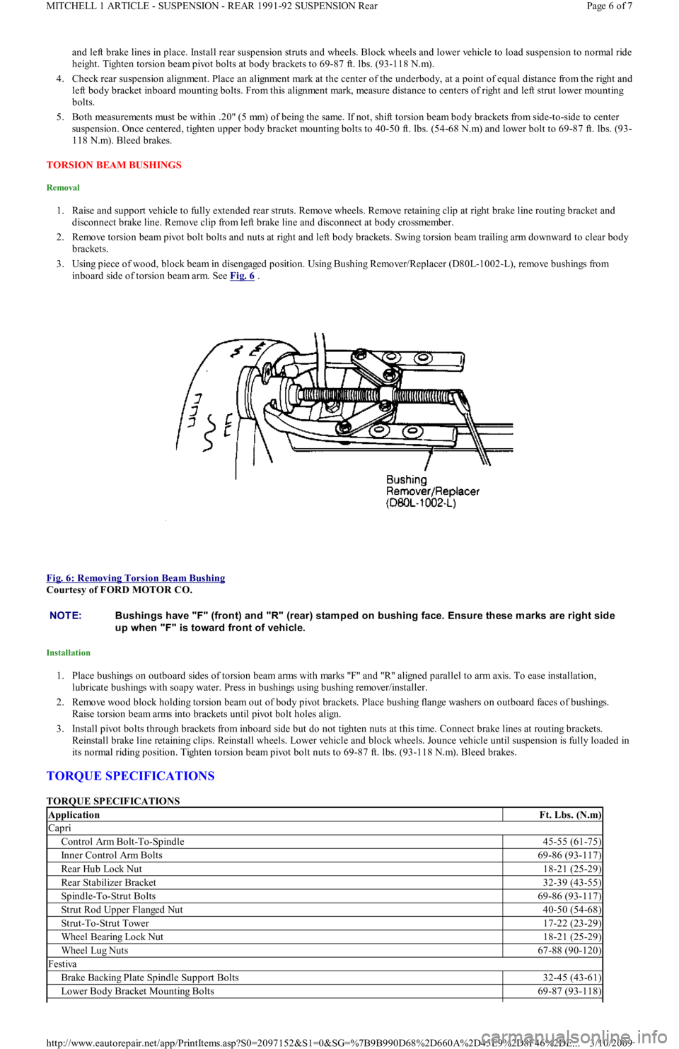
3. Using piece of wood, block beam in disengaged position. Using Bushing Remover/Replacer (D80L-1002-L), remove bushings from
inboard side of torsion beam arm. See Fig. 6
.
Fig. 6: Removing Torsion Beam Bushing
Courtesy of FORD MOTOR CO.
Installation
1. Place bushings on outboard sides of torsion beam arms with marks "F" and "R" aligned parallel to arm axis. To ease installation,
lubricate bushings with soapy water. Press in bushings using bushing remover/installer.
2. Remove wood block holding torsion beam out of body pivot brackets. Place bushing flange washers on outboard faces of bushings.
Raise torsion beam arms into brackets until pivot bolt holes align.
3. Install pivot bolts through brackets from inboard side but do not tighten nuts at this time. Connect brake lines at routing brackets.
Reinstall brake line retaining clips. Reinstall wheels. Lower vehicle and block wheels. Jounce vehicle until suspension is fully loaded in
its normal riding position. Tighten torsion beam pivot bolt nuts to 69-87 ft. lbs. (93-118 N.m). Bleed brakes.
TORQUE SPECIFICATIONS
TORQUE SPECIFICATIONS
NOTE:Bushings have "F" (front) and "R" (rear) stam ped on bushing face. Ensure these m arks are right side
up when "F" is toward front of vehicle.
ApplicationFt. Lbs. (N.m)
Capri
Control Arm Bolt-To-Spindle45-55 (61-75)
Inner Control Arm Bolts69-86 (93-117)
Rear Hub Lock Nut18-21 (25-29)
Rear Stabilizer Bracket32-39 (43-55)
Spindle-To-Strut Bolts69-86 (93-117)
Strut Rod Upper Flanged Nut40-50 (54-68)
Strut-To-Strut Tower17-22 (23-29)
Wheel Bearing Lock Nut18-21 (25-29)
Wheel Lug Nuts67-88 (90-120)
Festiva
Brake Backing Plate Spindle Support Bolts32-45 (43-61)
Lower Body Bracket Mounting Bolts69-87 (93-118)
Page 6 of 7 MITCHELL 1 ARTICLE - SUSPENSION - REAR 1991-92 SUSPENSION Rear
3/10/2009 http://www.eautorepair.net/app/PrintItems.asp?S0=2097152&S1=0&SG=%7B9B990D68%2D660A%2D45E9%2D8F46%2DE
...
Page 402 of 454

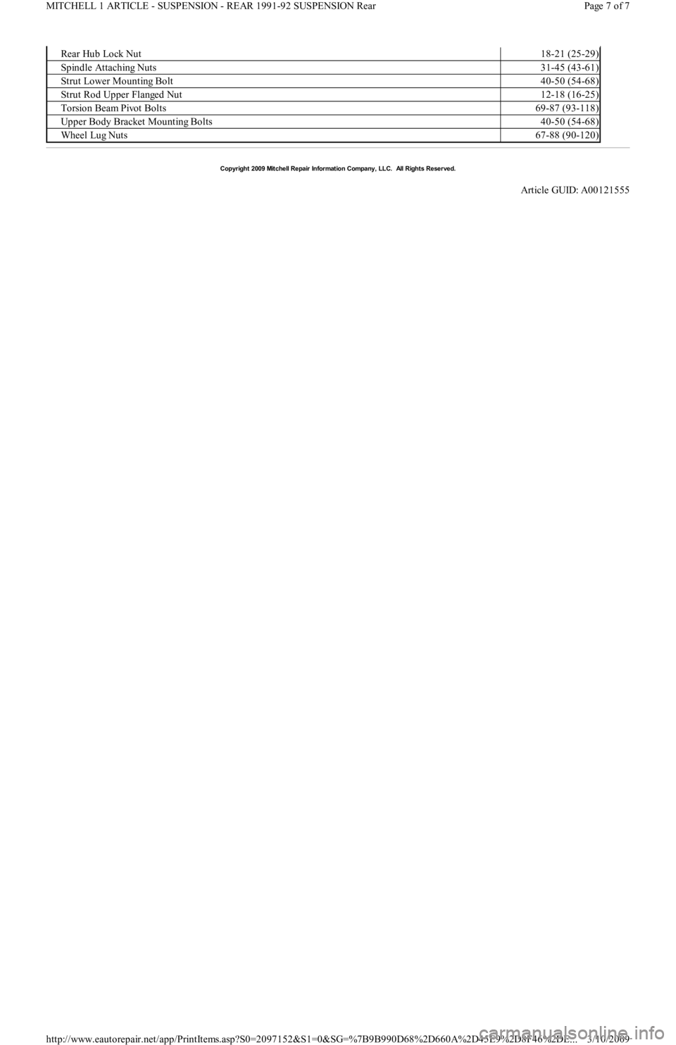
Rear Hub Lock Nut18-21 (25-29)
Spindle Attaching Nuts31-45 (43-61)
Strut Lower Mounting Bolt40-50 (54-68)
Strut Rod Upper Flanged Nut12-18 (16-25)
Torsion Beam Pivot Bolts69-87 (93-118)
Upper Body Bracket Mounting Bolts40-50 (54-68)
Wheel Lug Nuts67-88 (90-120)
Copyr ight 2009 Mitchell Repair Information Company, LLC. All Rights Reserved.
Article GUID: A00121555
Page 7 of 7 MITCHELL 1 ARTICLE - SUSPENSION - REAR 1991-92 SUSPENSION Rear
3/10/2009 http://www.eautorepair.net/app/PrintItems.asp?S0=2097152&S1=0&SG=%7B9B990D68%2D660A%2D45E9%2D8F46%2DE
...