remove seats FORD FESTIVA 1991 Service Manual
[x] Cancel search | Manufacturer: FORD, Model Year: 1991, Model line: FESTIVA, Model: FORD FESTIVA 1991Pages: 454, PDF Size: 9.53 MB
Page 102 of 454
levels to proper level.
Removal (1.6L & 1.6L Turbo)
1. Relieve fuel pressure and discharge air conditioning system (if equipped). See FUEL PRESSURE RELEASE under REMOVAL &
INSTALLATION. Disconnect and remove battery, battery tray and battery tray support bracket.
2. Release wiring harness retaining straps from battery support tray. Disconnect windshield washer supply hose between fluid reservoir and
hood. Mark hinge locations and remove hood.
3. Disconnect intake air tube and wiring to ignition coil and vane airflow meter. Remove air cleaner/vane airflow meter assembly. Remove
air cleaner assembly support brackets. Disconnect intercooler hoses from turbocharger (if equipped).
4. Drain engine coolant and remove radiator. Disconnect accelerator cable, and remove retaining bracket from cam cover. Position cable to
one side.
5. Disconnect and plug fuel lines at fuel filter and pressure regulator. Disconnect power brake booster manifold vacuum hose from
manifold. Disconnect heater hoses at heater core tubes. Label and remove vacuum hoses located at throttle body.
6. For manual transaxle turbocharged vehicles, disconnect clutch cable and remove support bracket and cable from transmission. On non-
turbo vehicles, disconnect clutch slave hydraulic line. For automatic transaxle, remove transaxle cooler lines.
7. Disconnect starter wiring at starter. Remove harness from locating strap on bracket. Disconnect alternator wiring. Disconnect wiring
from engine coolant sensors located on rear of engine block. Remove ground connection at bracket on thermostat cover. Disconnect O2
sensor wire, main wiring harness connector, TPS connector (turbocharged only), knock sensor connector, distributor wiring and
transaxle wiring. Disconnect ground wire and strap at front of engine, and reinstall lifting eye.
8. Remove engine oil dipstick and retaining clip. Remove power steering pump from mounting bracket. Remove power steering pump
mounting bracket. With hoses attached, position pump aside. Remove upper air conditioning compressor retaining bolts (if equipped).
9. Raise vehicle on hoist. Drain engine oil and cooling system. On vehicles with air conditioning, remove lower air conditioning
compressor mounting bolts, and position compressor out of way.
10. Remove front wheels and tires. Remove front ball joints-to-ste e r in g kn u c kl e s r e t a in in g b o l t s. R e mo ve sp l a sh gu a r d s. Dr a in t ransmission
oil and remove half shafts from differential. Remove front exhaust pipe bracket located on lower side of engine. Disconnect front
exhaust pipe from exhaust manifold, or turbocharger (if equipped).
11. Remove frame support bar-to-engine support bolt. Loosen right control arm bolt and, pivot support bar downward. Disengage rubber
exhaust hangers located directly behind catalytic converter. Allow exhaust system to hang down 6 inches, and support system with
mechanic's wire. Unbolt shift linkage and stabilizer bar at transaxle. Remove nuts from front and rear engine mounts, and lower vehicle.
12. Attach chains onto lift eyes at ends of cylinder head, and support engine with hoist. Remove RH engine mount through bolt. Raise
engine off mounts and slightly pivot engine/transaxle assembly. Disconnect oil pressure sensor and route starter/alternator wiring
harness from engine. Carefully lift engine/transaxle assembly, turn assembly while raising to clear brake master cylinder, shift linkage
universal joint, radiator support and air conditioning lines (if equipped).
13. Remove intake manifold support bracket. Remove gusset plate(s) (if equipped). Remove starter. Remove transaxle-to-engine retaining
bolts. Identify bolts to ensure correct installation. Separate transaxle from engine. On manual transaxle, remove pressure plate, clutch
disc and flywheel. On automatic transaxle, remove flexplate.
Installation (1.6L & 1.6L Turbo)
1. Install transaxle to engine in reverse order of removal. Attach hoist to engine/transaxle assembly and position assembly in vehicle.
Before engine contacts mounts, route starter, alternator and oil pressure sensor wiring, and connect oil pressure sensor. Lower engine
until front mount seats on crossmember. Install through bolt on RH engine mount. DO NOT tighten bolt.
2. Remove hoist. Raise vehicle and support with jackstands. Align rear engine mount to crossmember, and install retaining nuts to front
and rear engine mounts. Tighten nuts to specification. See TORQUE SPECIFICATIONS
table at end of article.
3. On manual transaxles, connect shift coupling and stabilizer. Tighten to specification. On automatic transaxles, connect shift linkage and
oil cooler lines. Tighten linkage retaining bolt, shift cable pivot and oil cooler hose clamps to specification. Connect front exhaust pipe
to manifold (or turbocharger). Install exhaust pipe to support bracket. Tighten bolts to specification. Tighten manifold (or turbocharger)
to specification. Attach rubber exhaust hangers. Position cross brace. Tighten retaining nut and bolt and right control arm front bolt.
4. Install drive axles. Install ball joint retaining bolts and tighten to specification. Mount A/C Compressor to engine (if equipped). Tighten
lower retaining bolts to specification. Install splash guards. Install tire and wheel assemblies. Tighten retaining nuts to specification.
5. Lower vehicle. Install upper A/C compressor retaining bolts (if equipped). Tighten bolts to specification. Tighten RH engine mo u n t
through bolt to specification. Connect alternator wiring.
6. Position power steering pump bracket on stud. Lower pump into engine compartment. Install power steering pump bracket retaining
bolts and nut. Tighten to specification. Install power steering pump and belt. Tighten adjustment nut and pivot bolt to specification.
7. Install engine oil dipstick and retaining clip. Install ground strap and ground wire to cylinder head. Install clutch cable (if equipped).
Connect clutch hydraulic line if equipped with manual transaxle or naturally aspirated. Connect transmission electrical connectors.
Connect fuel lines to fuel filter and pressure regulator. Install intake air tube to throttle body.
8. Install intercooler hoses on turbocharged models. Install air cleaner assembly brackets. Install air cleaner assembly with airflow meter
attached. Install intake air tube. Install coil and airflow meter connectors. Connect coolant crankcase and air bypass hoses. Install
vacuum hoses as noted in disassembly.
9. Connect accelerator cable. Install retaining bracket. Install power brake booster hose. Remove speedometer cable from transaxle. Fill
transaxle to specification. See CAPACITIES in SERVICE & ADJUSTMENT SPECIFICATIONS article. Install speedometer cable.
Connect speedometer cable connector. Fill engine oil to capacity.
10. Install radiator/fan assembly. Tighten bracket retaining bolts to specification. Connect coolant hoses and fan electrical connector. Fill
coolant to specification.
11. Install hood and connect washer hose. Install battery tray support, battery tray, battery and battery hold-down. Connect battery
terminal. Evacuate and charge air conditioning system (if equipped). Road test vehicle and inspect for leaks.
INTAKE MANIFOLD
Removal (1.3L)
CAUT ION: DO NOT allow com pressor to hang by hoses. T ie up com pressor with m echanic's wire.
Page 2 of 19 MITCHELL 1 ARTICLE - ENGINE OVERHAUL 1991-92 FORD MOTOR CO. ENGINES 1.3L & 1.6L 4-Cylinder
3/10/2009 http://www.eautorepair.net/app/PrintItems.asp?S0=2097152&S1=0&SG=%7B959286D2%2D3A85%2D4BFC%2D9C5C%2D
...
Page 225 of 454
bolts
Noisy Pistons and Rings
Excessive piston-to-bore clearanceInstall larger pistons, See
ENGINES
Bore tapered or out-of-roundRebore block
Piston ring brokenReplace piston rings, See
ENGINES
Piston pin loose or seizedReplace piston pin, See
ENGINES
Connecting rods misalignedRealign connecting rods
Ring side clearance too loose or tightReplace with larger or smaller
rings
Carbon build-up on pistonRemove carbon
Noisy Valve Train
Worn or bent push rodsReplace push rods, See
ENGINES
Worn rocker arms or bridged pivotsReplace push rods, See
ENGINES
Dirt or chips in valve liftersRemove lifters and remove
dirt/chips
Excessive valve lifter leak-downReplace valve lifters, See
ENGINES
Valve lifter face wornReplace valve lifters, See
ENGINES
Broken or cocked valve springsReplace or reposition springs
Too much valve stem-to-guide clearanceReplace valve guides, See
ENGINES
Valve bentReplace valve, See ENGINES
Loose rocker armsRetighten rocker arms, See
ENGINES
Excessive valve seat run-outReface valve seats, See
ENGINES
Missing valve lockInstall new valve lock
Excessively worn camshaft lobesReplace camshaft, See
ENGINES
Plugged valve lifter oil holesEliminate restriction or
replace lifter
Faulty valve lifter check ballReplace lifter check ball, See
ENGINES
Rocker arm nut installed upside downRemove and reinstall correctly
Valve lifter incorrect for engineRemove and replace valve
lifters
Faulty push rod seat or lifter plungerReplace plunger or push rod
Noisy Valves
Improper valve lashRe-adjust valve lash, See
ENGINES
Worn or dirty valve liftersClean and/or replace lifters
Wo r n va l ve gu id e sReplace valve guides, See
ENGINES
Excessive valve seat or face run-outReface seats or valve face
Worn camshaft lobesReplace camshaft, See
ENGINES
Loose rocker arm studsRe-tighten rocker arm studs,
See ENGINES
Bent push rodsReplace push rods, See
ENGINES
Broken valve springsReplace valve springs, See
ENGINES
Burned,Sticking or Broken Valves
Weak valve springs or warped valvesReplace valves and/or springs,
See ENGINES
Improper lifter clearanceRe-adjust clearance or replace
lifters
Worn guides or improper guide clearanceReplace valve guides, See
ENGINES
Out-of-round valve seats or improper seat widthRe-grind valve seats
Gum deposits on valve stems, seats or guideRemove deposits
Improper spark timingRe-adjust spark timing
Broken Pistons/Rings
Undersize pistonsReplace with larger pistons,
See ENGINES
Wrong piston ringsReplace with correct rings,
See ENGINES
Out-of-round cylinder boreRe-bore cylinder bore
Page 12 of 36 MITCHELL 1 ARTICLE - GENERAL INFORMATION Trouble Shooting - Basic Procedures
3/10/2009 http://www.eautorepair.net/app/PrintItems.asp?S0=2097152&S1=0&SG=%7B9B990D68%2D660A%2D45E9%2D8F46%2DE
...
Page 327 of 454
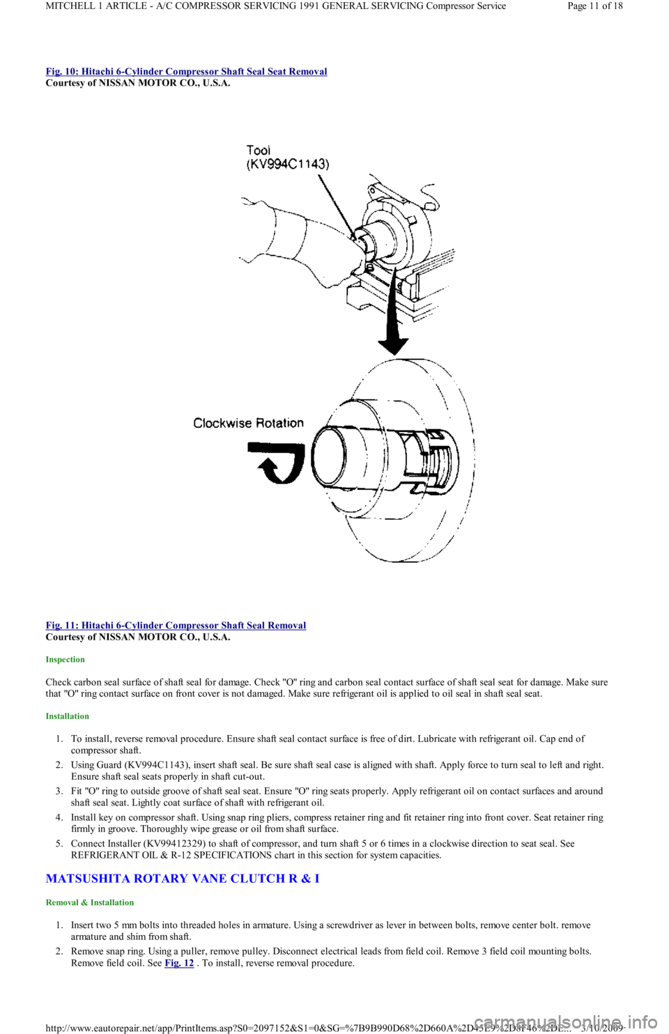
Fig. 10: Hitachi 6-Cylinder Compressor Shaft Seal Seat Removal
Courtesy of NISSAN MOTOR CO., U.S.A.
Fig. 11: Hitachi 6
-Cylinder Compressor Shaft Seal Removal
Courtesy of NISSAN MOTOR CO., U.S.A.
Inspection
Check carbon seal surface of shaft seal for damage. Check "O" ring and carbon seal contact surface of shaft seal seat for damage. Make sure
that "O" ring contact surface on front cover is not damaged. Make sure refrigerant oil is applied to oil seal in shaft seal seat.
Installation
1. To install, reverse removal procedure. Ensure shaft seal contact surface is free of dirt. Lubricate with refrigerant oil. Cap end of
compressor shaft.
2. Using Guard (KV994C1143), insert shaft seal. Be sure shaft seal case is aligned with shaft. Apply force to turn seal to left and right.
Ensure shaft seal seats properly in shaft cut-out.
3. Fit "O" ring to outside groove of shaft seal seat. Ensure "O" ring seats properly. Apply refrigerant oil on contact surfaces and around
shaft seal seat. Lightly coat surface of shaft with refrigerant oil.
4. Install key on compressor shaft. Using snap ring pliers, compress retainer ring and fit retainer ring into front cover. Seat retainer ring
firmly in groove. Thoroughly wipe grease or oil from shaft surface.
5. Connect Installer (KV99412329) to shaft of compressor, and turn shaft 5 or 6 times in a clockwise direction to seat seal. See
REFRIGERANT OIL & R-12 SPECIFICATIONS chart in this section for system capacities.
MATSUSHITA ROTARY VANE CLUTCH R & I
Removal & Installation
1. Insert two 5 mm bolts into threaded holes in armature. Using a screwdriver as lever in between bolts, remove center bolt. remove
armature and shim from shaft.
2. Remove snap ring. Using a puller, remove pulley. Disconnect electrical leads from field coil. Remove 3 field coil mounting bolts.
Remove field coil. See Fig. 12
. To install, reverse removal procedure.
Page 11 of 18 MITCHELL 1 ARTICLE - A/C COMPRESSOR SERVICING 1991 GENERAL SERVICING Compressor Service
3/10/2009 http://www.eautorepair.net/app/PrintItems.asp?S0=2097152&S1=0&SG=%7B9B990D68%2D660A%2D45E9%2D8F46%2DE
...
Page 346 of 454
5. Check blower motor fan switch continuity. Resistance should not exceed 4 ohms. See BLOWER MOTOR FAN SWITCH
CONTINUITY table. If continuity is not present, replace fan switch. If continuity is okay, repair open in Black wire from blower motor
switch to ground.
BLOWER MOTOR FAN SWITCH CONTINUITY
REMOVAL & INSTALLATION
CONTROL PANEL
1. Remove bezel screws and accessory bezel. Remove radio. Remove 4 screws securing control panel to instrument panel. Remove glove
box attaching screws and glove box. Remove the retaining clip and disconnect fresh/recirculation air door cable from mode door lever.
2. Disconnect mode select cable at mode control door lever. Disconnect temperature control cable at temperature control mode door lever.
Pull control panel away from instrument panel. Disconnect blower motor switch connector. Disconnect illumination electrical
connector. Remove control panel. To install, reverse removal procedure. Adjust control cables. See ADJUSTMENTS in this article.
BLOWER MOTOR FAN SWITCH
Remove control panel. See CONTROL PANEL R & I
. Remove blower motor fan switch knob. Remove attaching nut. To install, reverse
removal procedure.
HEATER CORE
1. Disconnect negative battery cable. Remove steering wheel by prying out center trim insert and removing steering wheel retaining nut.
Remove 2 steering wheel cover retaining screws and remove cover. Using a steering wheel puller, remove steering wheel.
2. Remove 5 screws and remove lower and upper steering column covers. Disconnect electrical connections and remove multifunction
switch. Remove 5 screws and pull instrument cluster hood rearward. Disconnect electrical connections and remove instrument cluster
hood.
3. Disconnect speedometer cable at transaxle. Remove 4 instrument cluster screws. Pull instrument cluster rearward and disconnect
speedometer cable and electrical connections. Remove instrument cluster.
4. Remove 2 center bracket mounting bolts under steering column and remove bracket. Remove glove box attaching screws and remove
glove box. Remove left and right heater ducts. Remove fuse panel cover. Remove 2 screws securing fuse panel and push fuse panel
inward. DO NOT remove fuse panel.
5. Slide both seats to most forward position. Remove 2 console attaching screws, located in front of seat belt anchors. Slide both seats to
rearmost position. Remove parking brake console insert. Using a Phillips screwdriver, remove push retainer insert, located at front lower
edge of parking brake console. Pull back on parking brake lever and remove parking brake console.
6. Remove gearshift knob. Remove screws and remove shift console. Remove radio/heater control panel bezel screws and remove bezel.
Remove 4 radio attaching screws. Pull radio out and disconnect antenna lead and electrical connections. Disconnect radio ground lead
and remove radio.
7. Remove 4 screws attaching heater control panel. Disconnect control cables and electrical connections. Remove control panel, while
pulling cables through opening.
8. Pry out bolt cover trim inserts in top corners of dash. Remove bolts located under trim panels. Remove 7 instrument panel attaching
bolts and 2 nuts. Pull instrument panel rearward. Disconnect any harness connectors and clips. Remove instrument panel.
9. Disconnect electrical connections at blower and resistor. Remove harness from routing brackets on heater box. Loosen clamp screw
securing air inlet housing. Remove attaching nuts at top and bottom of heater box. Disconnect defroster ducts and remove heater
assembly.
10. Disconnect link connecting 2 defroster doors. Remove attaching screw just above and to right of blower resistor. Turn heater assembly
around and remove screw just to left of blower motor opening. Remove clips securing 2 halves of heater assembly. Separate halves. Lift
out heater core.
11. To install, reverse removal procedure. Ensure all heater control cables are routed and adjusted properly. See ADJUSTMENTS in this
article. Fill cooling system. Check for leaks.
BLOWER MOTOR & RESISTOR
Disconnect negative battery cable. Remove instrument panel spacer brace located below steering column. Remove airflow duct below steering
column. Disconnect blower motor or resistor wiring. Remove 3 blower motor attaching screws or 2 resistor attaching screws and remove
component. To install, reverse removal procedure.
Switch PositionContinuity Between Wire Colors
1Black-to-Blue/White
2Black-to-Blue/Yellow & Blue/Yellow-to-Blue/Red
3Black-to-Blue/Black & Blue/Black-to-Blue/Red
Page 2 of 4 MITCHELL 1 ARTICLE - HEATER SYSTEM 1990-92 HEATER SYSTEMS Ford Motor Co.
3/10/2009 http://www.eautorepair.net/app/PrintItems.asp?S0=2097152&S1=0&SG=%7B9B990D68%2D660A%2D45E9%2D8F46%2DE
...
Page 379 of 454
1. Position steering gear in its mounting position. Attach intermediate shaft to steering gear pinion and tighten clamp bolt to 13-20 ft. lbs.
(18-26 N.m). Guide intermediate shaft into steering column hole. Lower vehicle.
2. Lift steering gear and align intermediate shaft with universal joint and install clamp bolt. Raise vehicle. Install steering gear mounting
bolts and tighten to 23-34 ft. lbs. (31-46 N.m). Install right tie rod end, using marks made during removal for installation reference.
Attach tie rod ends to steering knuckles. Install tie rod end nuts and tighten to 22-33 ft. lbs. (29-44 N.m).
3. Install tie rod end cotter pins. Attach catalytic converter to inlet pipe and install attaching nuts. Tighten nuts to 23-34 ft. lbs. (31-46
N.m). Install tie rod end splash shields. Install right fender splash shield. install front wheels. Lower vehicle.
4. Connect high pressure and return lines. Connect negative battery cable. Add power steering fluid and bleed air from system and check
for leaks. See HYDRAULIC FLUID BLEEDING
under LUBRICATION.
POWER STEERING PUMP
Removal (Capri)
1. Remove right radiator support and brace. Remove pump drive belt. Disconnect intercooler outlet hose at throttle intake (if equipped).
R e mo ve gr o u n d wir e fr o m e n gin e l ift in g e ye .
2. Remove pressure and return hoses and plug. Remove wire from pressure switch. Remove adjusting screw, nut and block from pump
bracket. Remove pivot bolt. Remove bracket retaining bolts then remove pump.
Removal (Festiva)
Remove air duct and air cleaner. Disconnect electrical connector from fluid pressure switch on power steering pump. Disconnect and plug
return and pressure lines. Remove adjustment bolt. Remove lock nut, washer and bracket bolt. Loosen mounting bolt and disconnect drive
belt. Remove mounting bolt. Remove power steering pump.
Installation (Capri & Festiva)
To install pump, reverse removal procedure. Adjust steering belt tension. Tighten all nuts and bolts to specification. See TORQUE
SPECIFICATIONS . Add power steering fluid and bleed air from system and check for leaks. See HYDRAULIC FLUID BLEEDING
under LUBRICATION.
OVERHAUL
STEERING GEAR
Disassembly (Capri)
1. Remove steering gear and place in soft-jawed vise. Remove external hydraulic lines. See Fig. 1 . Remove mount brackets and rubber
mount bushings. Remove brass tubing seats using a self-tapping screw and 2 screwdrivers.
Page 2 of 9 MITCHELL 1 ARTICLE - STEERING SYSTEM - POWER 1991-92 STEERING Ford Motor Co. - Steering - Power Rack & Pi
...
3/10/2009 http://www.eautorepair.net/app/PrintItems.asp?S0=2097152&S1=0&SG=%7B9B990D68%2D660A%2D45E9%2D8F46%2DE
...
Page 383 of 454
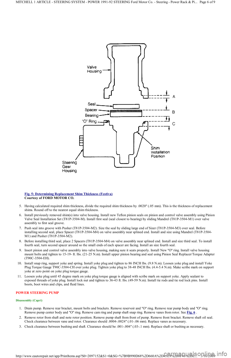
Fig. 5: Determining Replacement Shim Thickness (Festiva)
Courtesy of FORD MOTOR CO.
5. Having calculated required shim thickness, divide the required shim thickness by .0020" (.05 mm). This is the thickness of replacement
shims. Round off to the nearest equal shim thickness.
6. Install previously removed shim(s) into valve housing. Install new Teflon pinion seals on pinion and control valve assembly using Pinion
Valve Seal Installation Set (T81P-3504-M). Install first seal (seal closest to bearing) by sliding Mandrel (T81P-3504-M1) over va l ve
assembly to first seal groove.
7. Push seal into groove with Pusher (T81P-3504-M2). Size the seal by sliding large end of Sizer (T81P-3504-M3) over seal. Before
installing second seal, place Spacer (T81P-3504-M4) on valve assembly near splined end. Install and size using Mandrel (T81P-3504-
M1) and Pusher (T81P-3504-M2).
8. Before installing third seal, place 2 Spacers (T81P-3504-M4) on valve assembly near splined end. Install and size third seal. To install
fourth seal, turn second spacer around so the small ends of each spacer are facing. Install an size fourth seal.
9. Insert pinion and control valve assembly into valve housing, making sure it seats properly. Install New "O" ring. Install valve h o u sin g
mount bolts and tighten to 15-19- ft. lbs. (21-25 N.m). Install upper pinion bearing and seal using Pinion Seal Replacer/Torque Adapter
(T90C-3504-EH).
10. Install snap ring, support yoke and spring. Install yoke plug and tighten to 86 INCH lbs. (9.8 N.m). Loosen yoke plug and install Yoke
Plug Torque Gauge T90C-3504-CH over yoke plug. Tighten yoke plug to 38-48 INCH lbs. (4.4-5.4 N.m). Make scribe mark on support
yoke at zero point on yoke plug torque gauge.
11. Loosen yoke plug until 45 degree mark on yoke plug torque gauge is aligned with scribe mark on support yoke. Apply sealant to
exposed threads of yoke plug. Install lock nut and tighten to 36-43 ft. lbs. (49-59 N.m). Install tie rods and tie rod lock pins. Install
boots, boot wires and clips, and fluid lines.
POWER STEERING PUMP
Disassembly (Capri)
1. Drain pump. Remove rear bracket, mount bolts and brackets. Remove reservoir and "O" ring. Remove rear pump body and "O" ring.
Remove pump center body and "O" ring. Remove cam ring and pump shaft snap ring. Remove vanes from rotor. See Fig. 6
.
2. Remove rotor from shaft and note rotor position. Remove pump shaft from front of pump. Remove front bracket. Remove shaft oil seal.
Check clearance between vane and rotor. Clearance should .0004-.0024" (.01-.06 mm). Replace vanes as necessary.
3. Check clearance between bushing and shaft. Clearance should be .001-.004" (.03-.1 mm). Replace shaft or bushing as necessary.
Page 6 of 9 MITCHELL 1 ARTICLE - STEERING SYSTEM - POWER 1991-92 STEERING Ford Motor Co. - Steering - Power Rack & Pi
...
3/10/2009 http://www.eautorepair.net/app/PrintItems.asp?S0=2097152&S1=0&SG=%7B9B990D68%2D660A%2D45E9%2D8F46%2DE
...
Page 392 of 454
WHEEL BEARINGS
Wheel bearing preload is maintained by a selective spacer in the steering knuckle, between the inner and outer hub bearings. For adjustment
procedures and inspection, see WHEEL BEARING under REMOVAL & INSTALLATION.
BALL JOINT CHECKING
Raise and support vehicle until tire is just off ground. Move wheel vertically and check for play. If play is noticed between steering knuckle
and control arm, control arm assembly should be replaced. If play is present but ball joint is okay, wheel bearings should be checked for wear
and replaced if necessary.
REMOVAL & INSTALLATION
STABILIZER BAR
Removal & Installation (Festiva)
1. Remove stabilizer mounting bracket nuts and brackets. Remove split bushings from stabilizer bar. Remove stabilizer bushing nuts at
lower control arms. Remove rear dished washers and bushings.
2. To loosen stabilizer bar, pull forward from control arms. Remove front bushings and washers. Install control arm bushing washers on
ends of stabilizer and install control arm front bushings. Insert ends of stabilizer bar into control arm bushings and install rear bushings
and washers on stabilizer bar ends.
3. Install retaining nuts finger tight. Install split bushings on stabilizer cross bar with split side forward. Position split bushings next to
White locating marks on bar. Install stabilizer mounting brackets. Tighten all bolts and nuts to specification.
STRUT ASSEMBLY & COIL SPRING
Removal
1. Raise and support front of vehicle so struts are fully extended. Remove front wheels. Remove brake line clip from strut lower mounting
bracket and remove brake line.
2. Remove 2 bolts retaining strut lower bracket to steering knuckle. Working inside engine compartment, remove 2 nuts retaining strut
mounting block in strut tower. Disengage strut lower bracket from steering knuckle and lower strut from vehicle.
Disassembly & Reassembly
1. Using spring compressor, compress spring to unload strut. Pry out mounting block cap and remove strut upper nut and lock washer.
2. Remove strut mounting block and spacer plate. Remove washer, bearing seal and bearing from strut rod. Remove spring upper seat, seat
insulator and coil spring. Remove jounce bumper and dust shield from strut. Reverse disassembly procedure to install coil spring a n d
reassemble strut.
Installation
1. Position strut, with spacer plate installed, in strut tower with White alignment mark facing outward. Install and tighten nuts on upper
mounting block studs.
2. Install steering knuckle in strut lower bracket. To complete installation, reverse removal procedure. Tighten all bolts and nuts to
specification.
HUB & KNUCKLE ASSEMBLY
Removal
1. Raise and support vehicle. Remove wheel. Straighten staked edge of drive axle lock nut flange. DO NOT damage groove or threads in
end of drive axle. Apply brakes to prevent hub assembly from turning. Remove and discard drive axle lock nut.
2. Remove clip which secures brake hose to strut bracket. Remove cotter pin and tie rod end attaching nut. Using Tie Rod End Separator
(T85M-3395A), remove tie rod end from steering knuckle.
3. Remove brake caliper attaching bolts and remove assembly from steering knuckle. Do not allow caliper to hang by brake hose. Remove
clamp bolt and nut where lower control arm ball joint connects to steering knuckle.
4. Using a pry bar, pull down on lower control arm and release ball joint from steering knuckle. Remove 2 bolts which attach steering
knuckle between flanges of MacPherson strut bracket. Slide hub/knuckle assembly off end of drive axle. If binding is present or drive
hub is rusted to half-shaft, use a hub puller to push axle from drive hub.
Installation
1. Apply a thin coat of SAE 30 weight oil to drive axle splines. Slide steering knuckle/rotor/hub assembly onto drive axle. Stop at area
where uppermost arm of steering knuckle seats into MacPherson strut bracket.
2. To complete installation, reverse removal procedure. Install NEW drive axle lock nut. Tighten all bolts and nuts to specification. Stake
axle lock nut into shaft groove.
WHEEL BEARING NOTE:Inform ation for stabilizer bar rem oval and installation on Capri is not available from m anufacturer.
NOTE:Always use a new drive axle lock nut when servicing drive hub or drive axle.
CAUT ION: DO NOT use a pointed tool to stake nut. If lock nut flange cracks, even slightly, during staking process,
it m ust be replaced.
Page 2 of 5 MITCHELL 1 ARTICLE - SUSPENSION - FRONT 1991-92 SUSPENSION Front
3/10/2009 http://www.eautorepair.net/app/PrintItems.asp?S0=2097152&S1=0&SG=%7B9B990D68%2D660A%2D45E9%2D8F46%2DE
...
Page 398 of 454
1. Using Installer (T77F-1217-A), Driver Handle (T80T-4000-W) or proper sized brass drift and hammer, install inner and outer bearing
races. Pack bearings and hub area with Lubricant (C1AZ-1959D-B, C, D or E).
2. Position inner bearing in bearing hub. Lubricate grease seal lips and install seal. Ensure bearings and hub have sufficient lubricant. Place
brake drum bearings and hub assembly on spindle. To prevent damage to grease seal and spindle threads, ensure hub is correctly
centered on spindle.
3. Install outer bearing, washer and new lock nut. Stake lock nut with a blunt chisel. Adjust bearing preload. See ADJUSTMENTS &
INSPECTION.
SPINDLE
Removal & Installation (Capri)
Remove wheel, caliper and brake rotor. Loosen spindle-to-strut attaching bolts. Loosen outer rear control arm common bolt and nut. Remove
spindle-to-strut mount bolts and common control arm bolt. Remove spindle from strut. To install, reverse removal procedure.
Removal & Installation (Festiva)
Remove brake drum assembly. Remove 4 spindle attaching nuts located on inboard side of torsion beam. Support backing plate with wire and
remove spindle. To install, reverse removal procedure. Tighten spindle attaching nuts to 32-45 ft. lbs. (43-61 N.m).
STRUTS
Removal & Installation (Capri)
1. Remove wheel, caliper and brake rotor. Remove trailing arm bolt and spindle-to-strut attaching bolts. Put index mark on strut rubber
mounting bracket. Remove upper strut attaching nuts from inside vehicle. Remove strut.
2. Compress strut coil spring with Spring Compressor (T18P-5310-A) or similar. Remove strut nut while spring is compressed. Remove
rubber mounting bracket, upper and lower spring seats. Slowly release coil spring and remove spring compressor. Remove coil spring,
dust boot and rebound bumpers. To install, reverse removal procedure.
Removal (Festiva)
1. Raise and support vehicle. Remove rear wheels. Using Spring Compressor (T81P-5310-A), compress spring to unload strut. Remove rear
quarter trim panel from cargo compartment.
2. Remove jam nut and flanged nut from strut rod. Remove bushing washer and upper bushing. Remove strut lower end mounting bolt
from wheel support arm. Remove strut and separate it from spring and seat insulator. Remove lower bushing and jounce bumper seat
from strut rod. Slide jounce bumper and shield off strut. See Fig. 3
. NOTE:Nut m ust be replaced if lock flange splits or cracks during staking process. DO NOT stake with a sharp-
edged tool.
Page 3 of 7 MITCHELL 1 ARTICLE - SUSPENSION - REAR 1991-92 SUSPENSION Rear
3/10/2009 http://www.eautorepair.net/app/PrintItems.asp?S0=2097152&S1=0&SG=%7B9B990D68%2D660A%2D45E9%2D8F46%2DE
...
Page 399 of 454
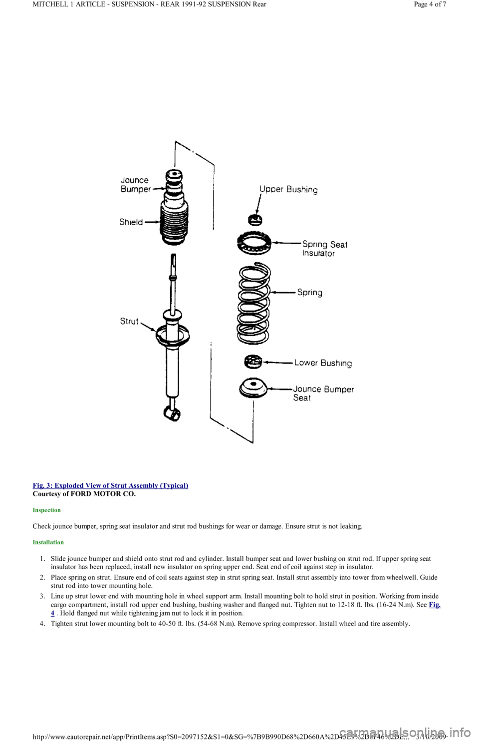
Fig. 3: Exploded View of Strut Assembly (Typical)
Courtesy of FORD MOTOR CO.
Inspection
Check jounce bumper, spring seat insulator and strut rod bushings for wear or damage. Ensure strut is not leaking.
Installation
1. Slide jounce bumper and shield onto strut rod and cylinder. Install bumper seat and lower bushing on strut rod. If upper spring seat
insulator has been replaced, install new insulator on spring upper end. Seat end of coil against step in insulator.
2. Place spring on strut. Ensure end of coil seats against step in strut spring seat. Install strut assembly into tower from wheelwell. Guide
strut rod into tower mounting hole.
3. Line up strut lower end with mounting hole in wheel support arm. Install mounting bolt to hold strut in position. Working from in sid e
cargo compartment, install rod upper end bushing, bushing washer and flanged nut. Tighten nut to 12-18 ft. lbs. (16-24 N.m). See Fig.
4 . Hold flanged nut while tightening jam nut to lock it in position.
4. Tighten strut lower mounting bolt to 40-50 ft. lbs. (54-68 N.m). Remove spring compressor. Install wheel and tire assembly.
Page 4 of 7 MITCHELL 1 ARTICLE - SUSPENSION - REAR 1991-92 SUSPENSION Rear
3/10/2009 http://www.eautorepair.net/app/PrintItems.asp?S0=2097152&S1=0&SG=%7B9B990D68%2D660A%2D45E9%2D8F46%2DE
...