run flat FORD FESTIVA 1991 Service Manual
[x] Cancel search | Manufacturer: FORD, Model Year: 1991, Model line: FESTIVA, Model: FORD FESTIVA 1991Pages: 454, PDF Size: 9.53 MB
Page 220 of 454
BRAKES
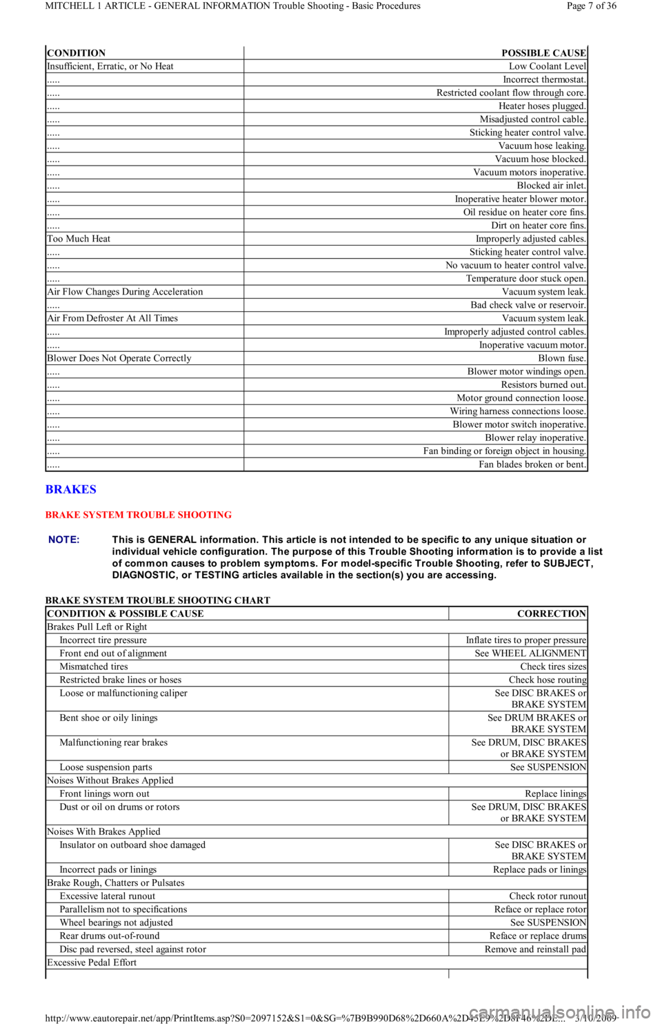
BRAKE SYSTEM TROUBLE SHOOTING
BRAKE SYSTEM TROUBLE SHOOTING CHART
CONDITIONPOSSIBLE CAUSE
Insufficient, Erratic, or No HeatLow Coolant Level
.....Incorrect thermostat.
.....Restricted coolant flow through core.
.....Heater hoses plugged.
.....Misadjusted control cable.
.....Sticking heater control valve.
.....Vacuum hose leaking.
.....Vacuum hose blocked.
.....Vacuum motors inoperative.
.....Blocked air inlet.
.....Inoperative heater blower motor.
.....Oil residue on heater core fins.
.....Dirt on heater core fins.
Too Much HeatImproperly adjusted cables.
.....Sticking heater control valve.
.....No vacuum to heater control valve.
.....Temperature door stuck open.
Air Flow Changes During AccelerationVacuum system leak.
.....Bad check valve or reservoir.
Air From Defroster At All TimesVacuum system leak.
.....Improperly adjusted control cables.
.....Inoperative vacuum motor.
Blower Does Not Operate CorrectlyBlown fuse.
.....Blower motor windings open.
.....Resistors burned out.
.....Motor ground connection loose.
.....Wiring harness connections loose.
.....Blower motor switch inoperative.
.....Blower relay inoperative.
.....Fan binding or foreign object in housing.
.....Fan blades broken or bent.
NOTE:This is GENERAL inform ation. This article is not intended to be specific to any unique situation or
individual vehicle configuration. T he purpose of this T rouble Shooting inform ation is to provide a list
of com m on causes to problem sym ptom s. For m odel-specific T rouble Shooting, refer to SUBJECT ,
DIAGNOST IC, or T EST ING articles available in the section(s) you are accessing.
CONDITION & POSSIBLE CAUSECORRECTION
Brakes Pull Left or Right
Incorrect tire pressureInflate tires to proper pressure
Front end out of alignmentSee WHEEL ALIGNMENT
Mismatched tiresCheck tires sizes
Restricted brake lines or hosesCheck hose routing
Loose or malfunctioning caliperSee DISC BRAKES or
BRAKE SYSTEM
Bent shoe or oily liningsSee DRUM BRAKES or
BRAKE SYSTEM
Malfunctioning rear brakesSee DRUM, DISC BRAKES
or BRAKE SYSTEM
Loose suspension partsSee SUSPENSION
Noises Without Brakes Applied
Front linings worn outReplace linings
Dust or oil on drums or rotorsSee DRUM, DISC BRAKES
or BRAKE SYSTEM
Noises With Brakes Applied
Insulator on outboard shoe damagedSee DISC BRAKES or
BRAKE SYSTEM
Incorrect pads or liningsReplace pads or linings
Brake Rough, Chatters or Pulsates
Excessive lateral runoutCheck rotor runout
Parallelism not to specificationsReface or replace rotor
Wheel bearings not adjustedSee SUSPENSION
Rear drums out-of-roundReface or replace drums
Disc pad reversed, steel against rotorRemove and reinstall pad
Excessive Pedal Effort
Page 7 of 36 MITCHELL 1 ARTICLE - GENERAL INFORMATION Trouble Shooting - Basic Procedures
3/10/2009 http://www.eautorepair.net/app/PrintItems.asp?S0=2097152&S1=0&SG=%7B9B990D68%2D660A%2D45E9%2D8F46%2DE
...
Page 249 of 454
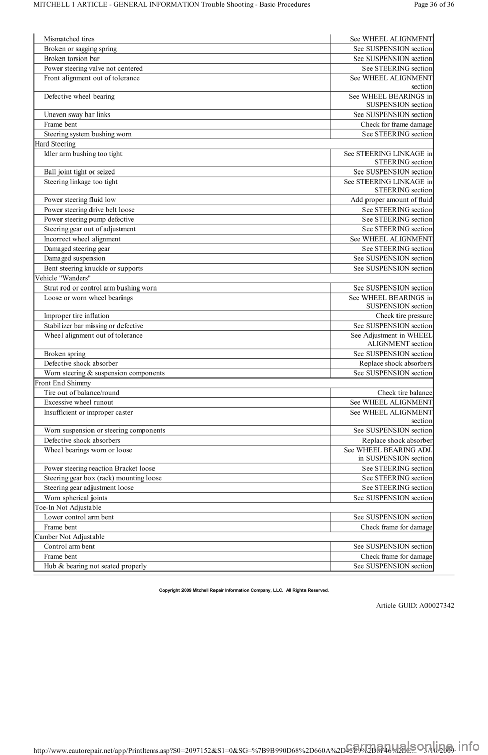
Mismatched tiresSee WHEEL ALIGNMENT
Broken or sagging springSee SUSPENSION section
Broken torsion barSee SUSPENSION section
Power steering valve not centeredSee STEERING section
Front alignment out of toleranceSee WHEEL ALIGNMENT
section
Defective wheel bearingSee WHEEL BEARINGS in
SUSPENSION section
Uneven sway bar linksSee SUSPENSION section
Frame bentCheck for frame damage
Steering system bushing wornSee STEERING section
Hard Steering
Idler arm bushing too tightSee STEERING LINKAGE in
STEERING section
Ball joint tight or seizedSee SUSPENSION section
Steering linkage too tightSee STEERING LINKAGE in
STEERING section
Power steering fluid lowAdd proper amount of fluid
Power steering drive belt looseSee STEERING section
Power steering pump defectiveSee STEERING section
Steering gear out of adjustmentSee STEERING section
Incorrect wheel alignmentSee WHEEL ALIGNMENT
Damaged steering gearSee STEERING section
Damaged suspensionSee SUSPENSION section
Bent steering knuckle or supportsSee SUSPENSION section
Vehicle "Wanders"
Strut rod or control arm bushing wornSee SUSPENSION section
Loose or worn wheel bearingsSee WHEEL BEARINGS in
SUSPENSION section
Improper tire inflationCheck tire pressure
Stabilizer bar missing or defectiveSee SUSPENSION section
Wheel alignment out of toleranceSee Adjustment in WHEEL
ALIGNMENT section
Broken springSee SUSPENSION section
Defective shock absorberReplace shock absorbers
Worn steering & suspension componentsSee SUSPENSION section
Front End Shimmy
Tire out of balance/roundCheck tire balance
Excessive wheel runoutSee WHEEL ALIGNMENT
Insufficient or improper casterSee WHEEL ALIGNMENT
section
Worn suspension or steering componentsSee SUSPENSION section
Defective shock absorbersReplace shock absorber
Wheel bearings worn or looseSee WHEEL BEARING ADJ.
in SUSPENSION section
Power steering reaction Bracket looseSee STEERING section
Steering gear box (rack) mounting looseSee STEERING section
Steering gear adjustment looseSee STEERING section
Worn spherical jointsSee SUSPENSION section
Toe-In Not Adjustable
Lower control arm bentSee SUSPENSION section
Frame bentCheck frame for damage
Camber Not Adjustable
Control arm bentSee SUSPENSION section
Frame bentCheck frame for damage
Hub & bearing not seated properlySee SUSPENSION section
Copyr ight 2009 Mitchell Repair Information Company, LLC. All Rights Reserved.
Article GUID: A00027342
Page 36 of 36 MITCHELL 1 ARTICLE - GENERAL INFORMATION Trouble Shooting - Basic Procedures
3/10/2009 http://www.eautorepair.net/app/PrintItems.asp?S0=2097152&S1=0&SG=%7B9B990D68%2D660A%2D45E9%2D8F46%2DE
...
Page 287 of 454
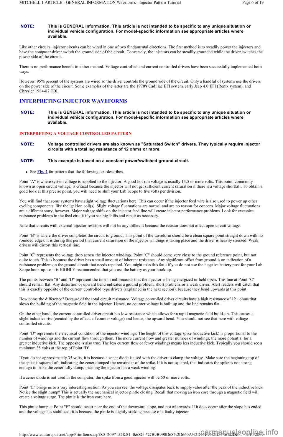
Like other circuits, injector circuits can be wired in one of two fundamental directions. The first method is to steadily power the injectors and
have the computer driver switch the ground side of the circuit. Conversely, the injectors can be steadily grounded while the driver switches the
power side of the circuit.
There is no performance benefit to either method. Voltage controlled and current controlled drivers have been successfully implemented both
ways.
However, 95% percent of the systems are wired so the driver controls the ground side of the circuit. Only a handful of systems use the drivers
on the power side of the circuit. Some examples of the latter are the 1970's Cadillac EFI system, early Jeep 4.0 EFI (Renix system), and
Chrysler 1984-87 TBI.
INTERPRETING INJECTOR WAVEFORMS
INTERPRETING A VOLTAGE CONTROLLED PATTERN
See Fig. 2 for pattern that the following text describes.
Point "A" is where system voltage is supplied to the injector. A good hot run voltage is usually 13.5 or more volts. This point, commonly
known as open circuit voltage, is critical because the injector will not get sufficient current saturation if there is a voltage shortfall. To obtain a
good look at this precise point, you will need to shift your Lab Scope to five volts per division.
You will find that some systems have slight voltage fluctuations here. This can occur if the injector feed wire is also used to power up other
cycling components, like the ignition coil(s). Slight voltage fluctuations are normal and are no reason for concern. Major voltage fluctuations
are a different story, however. Major voltage shifts on the injector feed line will create injector performance problems. Look for excessive
resistance problems in the feed circuit if you see big shifts and repair as necessary.
Note that circuits with external injector resistors will not be any different because the resistor does not affect open circuit voltage.
Point "B" is where the driver completes the circuit to ground. This point of the waveform should be a clean square point straight down with no
rounded edges. It is during this period that current saturation of the injector windings is taking place and the driver is heavily stressed. Weak
drivers will distort this vertical line.
Point "C" represents the voltage drop across the injector windings. Point "C" should come very close to the ground reference point, but not
quite touch. This is because the driver has a small amount of inherent resistance. Any significant offset from ground is an indication of a
resistance problem on the ground circuit that needs repaired. You might miss this fault if you do not use the negative battery post for your Lab
Scope hook-up, so it is HIGHLY recommended that you use the battery as your hook-up.
The points between "B" and "D" represent the time in milliseconds that the injector is being energized or held open. This line at Po int "C"
should remain flat. Any distortion or upward bend indicates a ground problem, short problem, or a weak driver. Alert readers will catch that
this is exactly opposite of the current controlled type drivers (explained in the next section), because they bend upwards at this point.
How come the difference? Because of the total circuit resistance. Voltage controlled driver circuits have a high resistance of 12+ ohms that
slows the building of the magnetic field in the injector. Hence, no counter voltage is built up and the line remains flat.
On the other hand, the current controlled driver circuit has low resistance which allows for a rapid magnetic field build-up. This causes a
slight inductive rise (created by the effects of counter voltage) and hence, the upward bend. You should not see that here with voltage
controlled circuits.
Point "D" represents the electrical condition of the injector windings. The height of this voltage spike (inductive kick) is proportional to the
number of windings and the current flow through them. The more current flow and greater number of windings, the more potential fo r a
greater inductive kick. The opposite is also true. The less current flow or fewer windings means less inductive kick. Typically you should see a
min imu m 3 5 vo l t s at t h e t o p o f Po in t "D".
If you do see approximately 35 volts, it is because a zener diode is used with the driver to clamp the voltage. Make sure the beginning top of
the spike is squared off, indicating the zener dumped the remainder of the spike. If it is not squared, that indicates the spike is not strong
enough to make the zener fully dump, meaning the injector has a weak winding.
If a zener diode is not used in the computer, the spike from a good injector will be 60 or more volts.
Point "E" brings us to a very interesting section. As you can see, the voltage dissipates back to supply value after the peak of the inductive kick.
Notice the slight hump? This is actually the mechanical injector pintle closing. Recall that moving an iron core through a magnetic field will
create a voltage surge. The pintle is the iron core here.
This pintle hump at Point "E" should occur near the end of the downward slope, and not afterwards. If it does occur after the slope has ended
and the voltage has stabilized, it is because the pintle is slightly sticking because of a faulty injector NOTE:This is GENERAL inform ation. This article is not intended to be specific to any unique situation or
individual vehicle configuration. For m odel-specific inform ation see appropriate articles where
available.
NOTE:This is GENERAL inform ation. This article is not intended to be specific to any unique situation or
individual vehicle configuration. For m odel-specific inform ation see appropriate articles where
available.
NOTE:Voltage controlled drivers are also known as "Saturated Switch" drivers. T hey typically require injector
circuits with a total leg resistance of 12 ohm s or m ore.
NOTE:T his exam ple is based on a constant power/switched ground circuit.
Page 6 of 19 MITCHELL 1 ARTICLE - GENERAL INFORMATION Waveforms - Injector Pattern Tutorial
3/10/2009 http://www.eautorepair.net/app/PrintItems.asp?S0=2097152&S1=0&SG=%7B9B990D68%2D660A%2D45E9%2D8F46%2DE
...
Page 289 of 454
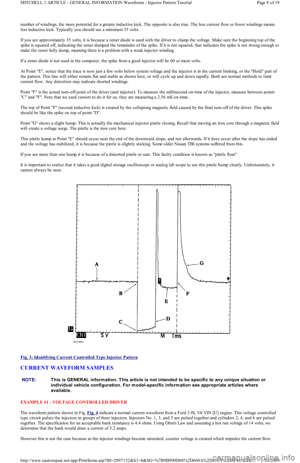
number of windings, the more potential for a greater inductive kick. The opposite is also true. The less current flow or fewer windings means
less inductive kick. Typically you should see a minimum 35 volts.
If you see approximately 35 volts, it is because a zener diode is used with the driver to clamp the voltage. Make sure the beginning top of the
spike is squared off, indicating the zener dumped the remainder of the spike. If it is not squared, that indicates the spike is not strong enough to
make the zener fully dump, meaning there is a problem with a weak injector winding.
If a zener diode is not used in the computer, the spike from a good injector will be 60 or more volts.
At Point "E", notice that the trace is now just a few volts below system voltage and the injector is in the current limiting, or the "Hold" part of
the pattern. This line will either remain flat and stable as shown here, or will cycle up and down rapidly. Both are normal methods to limit
current flow. Any distortion may indicate shorted windings.
Point "F" is the actual turn-off point of the driver (and injector). To measure the millisecond on-time of the injector, measure between points
"C" an d "F". No t e t h at we u sed cu rso rs t o d o it for us; they are measuring a 2.56 mS on-time.
The top of Point "F" (second inductive kick) is created by the collapsing magnetic field caused by the final turn-off of the driver. This spike
should be like the spike on top of point "D".
Point "G" shows a slight hump. This is actually the mechanical injector pintle closing. Recall that moving an iron core through a magnetic field
will create a voltage surge. The pintle is the iron core here.
This pintle hump at Point "E" should occur near the end of the downward slope, and not afterwards. If it does occur after the slope has ended
and the voltage has stabilized, it is because the pintle is slightly sticking. Some older Nissan TBI systems suffered from this.
If you see more than one hump it is because of a distorted pintle or seat. This faulty condition is known as "pintle float".
It is important to realize that it takes a good digital storage oscilloscope or analog lab scope to see this pintle hump clearly. Unfortunately, it
cannot always be seen.
Fig. 3: Identifying Current Controlled Type Injector Pattern
CURRENT WAVEFORM SAMPLES
EXAMPLE #1 - VOLTAGE CONTROLLED DRIVER
The waveform pattern shown in Fig. Fig. 4
indicate a normal current waveform from a Ford 3.0L V6 VIN [U] engine. This voltage controlled
type circuit pulses the injectors in groups of three injectors. Injectors No. 1, 3, and 5 are pulsed together and cylinders 2, 4, and 6 are pulsed
together. The specification for an acceptable bank resistance is 4.4 ohms. Using Ohm's Law and assuming a hot run voltage of 14 vo l t s, we
determine that the bank would draw a current of 3.2 amps.
However this is not the case because as the injector windings become saturated, counter voltage is created which impedes the current flow.
NOTE:This is GENERAL inform ation. This article is not intended to be specific to any unique situation or
individual vehicle configuration. For m odel-specific inform ation see appropriate articles where
available.
Page 8 of 19 MITCHELL 1 ARTICLE - GENERAL INFORMATION Waveforms - Injector Pattern Tutorial
3/10/2009 http://www.eautorepair.net/app/PrintItems.asp?S0=2097152&S1=0&SG=%7B9B990D68%2D660A%2D45E9%2D8F46%2DE
...
Page 301 of 454
Back To Article
GENERAL INFORMATION
Wheel Alignm ent T heory & Operation
* PLEASE READ THIS FIRST *
PRE-ALIGNMENT INSTRUCTIONS
GENERAL ALIGNMENT CHECKS
Before adjusting wheel alignment, check the following:
Each axle uses tires of same construction and tread style, equal in tread wear and overall diameter. Verify that radial and axial runout is
not excessive. Inflation should be at manufacturer's specifications.
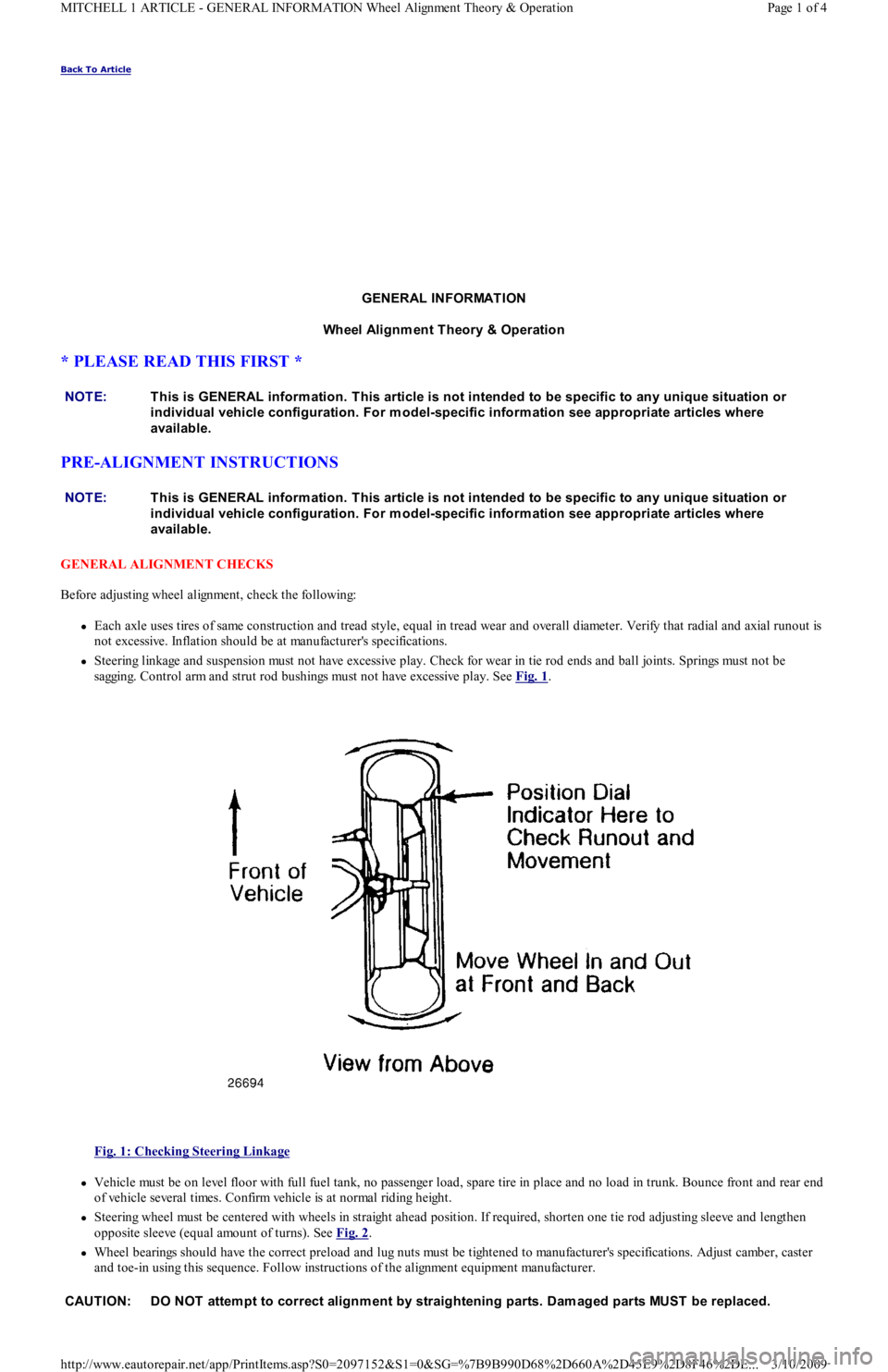
Steering linkage and suspension must not have excessive play. Check for wear in tie rod ends and ball joints. Springs must not be
sagging. Control arm and strut rod bushings must not have excessive play. See Fig. 1
.
Fig. 1: Checking Steering Linkage
Vehicle must be on level floor with full fuel tank, no passenger load, spare tire in place and no load in trunk. Bounce front and rear end
of vehicle several times. Confirm vehicle is at normal riding height.
Steering wheel must be centered with wheels in straight ahead position. If required, shorten one tie rod adjusting sleeve and lengthen
opposite sleeve (equal amount of turns). See Fig. 2
.
Wheel bearings should have the correct preload and lug nuts must be tightened to manufacturer's specifications. Adjust camber, caster
and toe-in using this sequence. Follow instructions of the alignment equipment manufacturer. NOTE:This is GENERAL inform ation. This article is not intended to be specific to any unique situation or
individual vehicle configuration. For m odel-specific inform ation see appropriate articles where
available.
NOTE:This is GENERAL inform ation. This article is not intended to be specific to any unique situation or
individual vehicle configuration. For m odel-specific inform ation see appropriate articles where
available.
CAUT ION: DO NOT attem pt to correct alignm ent by straightening parts. Dam aged parts MUST be replaced.
Page 1 of 4 MITCHELL 1 ARTICLE - GENERAL INFORMATION Wheel Alignment Theory & Operation
3/10/2009 http://www.eautorepair.net/app/PrintItems.asp?S0=2097152&S1=0&SG=%7B9B990D68%2D660A%2D45E9%2D8F46%2DE
...
Page 341 of 454
Back To Article
A/C SYST EM PRECAUT IONS
A/C GENERAL SERVICING A/C System Servicing cautions
BEFORE OPENING THE SYSTEM
Before disconnecting any lines or fittings, the system must be completely discharged using approved refrigerant recovery/recycling equipment.
DISCHARGING A/C SYSTEM
1. Remove service valve caps and install gauges. For high side gauge hose, Adapter (D81L-19703-A) must be used to connect to high side
service valve.
2. Place open end of center hose in garage exhaust outlet or in a well ventilated area. Slightly open low side gauge valve and let refrigerant
escape slowly without loosing refrigerant oil.
3. When system is nearly discharged, using approved refrigerant recovery/recycling equipment, open high side gauge valve to release any
pressure trapped in compressor. Close valves immediately after discharging to prevent entry of moisture.
DISCONNECTING LINES & FITTINGS
1. After system is discharged, using approved refrigerant recovery/recycling equipment, carefully clean entire area around coupling nut to
prevent dirt entering system. Always use two wrenches to avoid twisting or distorting lines and fittings (hold fitting with one wrench
while loosening coupling nut with second wrench).
2. Ford spring-coupling fittings require a special coupling tool (Motorcraft YT-1056) to open or close. See procedure under Connecting
Lines and Fittings.
3. Cap or plug all LINES and FITTINGS immediately to prevent entry of air and moisture into system. Do not remove these caps until
connections are being made.
COMPONENT REPLACEMENT
When components are replaced, system oil level must be adjusted. Add refrigeration oil to replacement component. See Compressor oil Check
article, as well as COMPONENT OIL REPLACEMENT QUANTITIES chart under A/C SYSTEM SPECS article in this section.
USING R-12 REFRIGERANT - SAFETY PRECAUTIONS
1. Always work in a well-ventilated, clean area. Refrigerant (R-12) is heavier than oxygen, and will displace oxygen in a confined area.
Always wear eye protection when working around air conditioning systems and R-12. The system's high pressure can cause severe injury
to eyes and skin if a hose were to burst. R-12 evaporates quickly when exposed to atmosphere, freezing anything it contacts.
2. Use care when handling refrigerant containers. DO NOT drop or strike containers or expose refrigerant containers to excessive heat.
Containers must never be heated more than 125°F (52°C). Never expose R-12 directly to open flame.
USING INDIVIDUAL R-12 CANS
Disposable refrigerant cans (referred to as one pound cans) have a flat type seal or a screw type seal, and proper can tap must be used for each
type. Be sure sealing gasket on can tap is in good condition. A proper safety can tap will prevent refrigerant from flowing back into open can,
as tap has a one-way flow control.
MULTI-CAN DISPENSING VALVES
A multi-can dispensing valve allows attachment of several cans of refrigerant, and is a good substitute when a bulk container is not available.
Cans are installed onto each leg of multi-can dispensing valve in the same manner as the individual cans, and each leg has its own can tap.
CAN TAP INSTALLATION FLAT TYPE SEAL CANS
On cam-lock or one-piece can taps, first turn the handle outward to the fully open position. Securely engage locking lugs over the can flange,
and lock them in place by turning cam lock or locking nut. Screw tap assembly into adapter so sealing gasket is fully seated against the can
top. Turn tap inward to pierce the can and close the tap. DO NOT open tap until ready to purge the service hose or dispense refrigerant into
the system.
On 2-piece can taps, be certain tap handle is turned fully inward to the closed position. Check that locking base is turned to its outer limit.
Securely engage locking lugs over the can flange. Turn entire tap assembly (without disturbing the closed setting) downward into the locking
base to pierce the can. DO NOT open tap until ready to dispense into system. CAUT ION: When discharging air conditioning system , use only approved refrigerant recovery/recycling
equipm ent. Make every attem pt to avoid discharging refrigerant into the atm osphere.
NOTE:Recent findings by the EPA indicate that R-11, R-12 and R-113 are harm ful to the Earths' protective
Ozone layer. Make every attem pt possible, to avoid discharging R-11, R-12 or R-113 into the
atm osphere.
CAUT ION: When R-12 is exposed to an open flam e, drawn into a running engine, or detected with a Halide
(propane) leak tester, poisonous phosgene gas is form ed. Keep work areas ventilated and avoid
running engines near work area.
NOTE:Recent findings by the EPA indicate that refrigerant is harm ful to the Earth's protective Ozone layer.
When discharging refrigerant avoid allowing refrigerant to enter the atm osphere. Refrigerant recovery
system should be used when discharging the system .
Page 1 of 2 MITCHELL 1 ARTICLE - A/C SYSTEM PRECAUTIONS A/C GENERAL SERVICING A/C System Servicing cautions
3/10/2009 http://www.eautorepair.net/app/PrintItems.asp?S0=2097152&S1=0&SG=%7B9B990D68%2D660A%2D45E9%2D8F46%2DE
...
Page 404 of 454
Back To Article
1983-95 WHEEL ALIGNMENT
Pre-Alignm ent Inspection Procedures
PRE-ALIGNMENT CHECKS
Before making wheel alignment adjustment, perform the following checks:
1. Tires should be equal in size and runout must not be excessive. Tires and wheels should be in balance, and inflated to manufacturer's
specifications.
2. Wheel bearings must be properly adjusted. Steering linkage and suspension must not have excessive looseness. Check for wear in tie rod
ends and ball joints.
3. Steering gear box must not have excessive play. Check and adjust to manufacturer's specifications.
4. Vehicle must be at curb height with full fuel load and spare tire in vehicle. No extra load should be on vehicle.
5. Vehicle must be level with floor and with suspension settled. Jounce front and rear of vehicle several times and allow it to settle to
normal curb height.
6. If steering wheel is not centered with front wheels in straight-ahead position, correct by shortening one tie rod adjusting sleeve and
lengthening opposite sleeve equal amounts.
7. Ensure wheel lug nuts are tightened to torque specifications.
Copyr ight 2009 Mitchell Repair Information Company, LLC. All Rights Reserved.
Article GUID: A00060347
Page 1 of 1 MITCHELL 1 ARTICLE - 1983-95 WHEEL ALIGNMENT Pre-Alignment Inspection Procedures
3/10/2009 http://www.eautorepair.net/app/PrintItems.asp?S0=2097152&S1=0&SG=%7B9B990D68%2D660A%2D45E9%2D8F46%2DE
...