service indicator FORD FESTIVA 1991 Service Manual
[x] Cancel search | Manufacturer: FORD, Model Year: 1991, Model line: FESTIVA, Model: FORD FESTIVA 1991Pages: 454, PDF Size: 9.53 MB
Page 4 of 454
Turbo Boost Gauge Always Reads High
If turbo boost gauge always reads high, check these items:
Check for damaged White/Black signal wire.
Check for defective boost sensing unit.
Check for defective boost gauge.
Turbo Boost Gauge Inaccurate
If turbo boost gauge is inaccurate, check these items:
Check for loose or corroded connections.
Check for defective boost sensing unit.
Check for defective boost gauge.
TESTING
FUEL GAUGE SENDING UNIT
Capri
Remove rear seat cushion. Disconnect fuel pump/fuel gauge sending unit electrical connector at access cover. Turn ignition on. Fuel gauge
should read empty. Using a jumper wire, connect Yellow fuel gauge wire of vehicle harness connector to ground. Fuel gauge should read full.
If fuel gauge operates as specified, replace fuel gauge sending unit.
Festiva
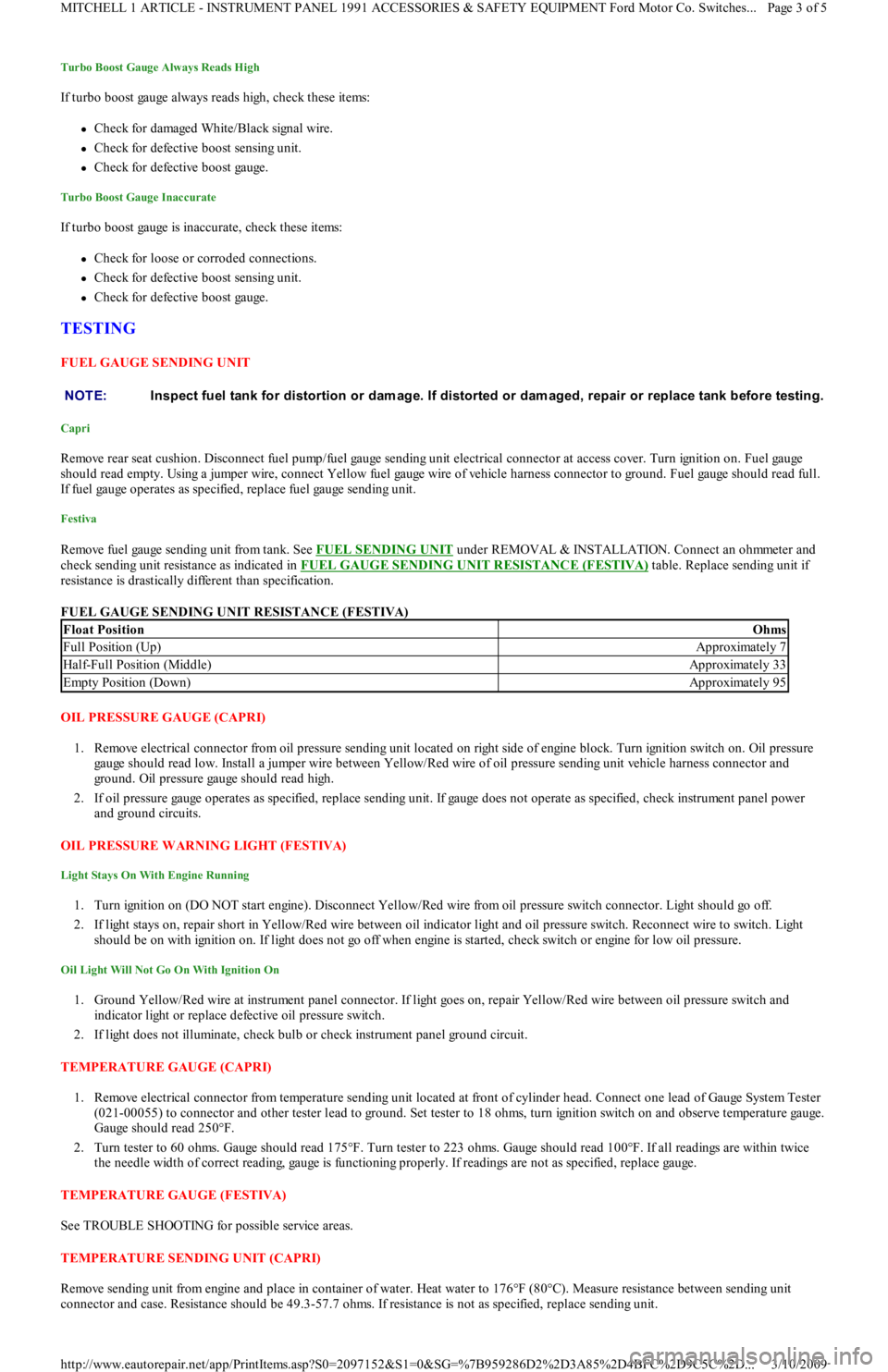
Remove fuel gauge sending unit from tank. See FUEL SENDING UNIT under REMOVAL & INSTALLATION. Connect an ohmmeter and
check sending unit resistance as indicated in FUEL GAUGE SENDING UNIT RESISTANCE (FESTIVA)
table. Replace sending unit if
resistance is drastically different than specification.
FUEL GAUGE SENDING UNIT RESISTANCE (FESTIVA)
OIL PRESSURE GAUGE (CAPRI)
1. Remove electrical connector from oil pressure sending unit located on right side of engine block. Turn ignition switch on. Oil pressure
gauge should read low. Install a jumper wire between Yellow/Red wire of oil pressure sending unit vehicle harness connector and
ground. Oil pressure gauge should read high.
2. If oil pressure gauge operates as specified, replace sending unit. If gauge does not operate as specified, check instrument panel power
and ground circuits.
OIL PRESSURE WARNING LIGHT (FESTIVA)
Light Stays On With Engine Running
1. Turn ignition on (DO NOT start engine). Disconnect Yellow/Red wire from oil pressure switch connector. Light should go off.
2. If light stays on, repair short in Yellow/Red wire between oil indicator light and oil pressure switch. Reconnect wire to switch. Light
should be on with ignition on. If light does not go off when engine is started, check switch or engine for low oil pressure.
Oil Light Will Not Go On With Ignition On
1. Ground Yellow/Red wire at instrument panel connector. If light goes on, repair Yellow/Red wire between oil pressure switch and
indicator light or replace defective oil pressure switch.
2. If light does not illuminate, check bulb or check instrument panel ground circuit.
TEMPERATURE GAUGE (CAPRI)
1. Remove electrical connector from temperature sending unit located at front of cylinder head. Connect one lead of Gauge System Tester
(021-00055) to connector and other tester lead to ground. Set tester to 18 ohms, turn ignition switch on and observe temperature gauge.
Gauge should read 250°F.
2. Turn tester to 60 ohms. Gauge should read 175°F. Turn tester to 223 ohms. Gauge should read 100°F. If all readings are within twice
the needle width of correct reading, gauge is functioning properly. If readings are not as specified, replace gauge.
TEMPERATURE GAUGE (FESTIVA)
See TROUBLE SHOOTING for possible service areas.
TEMPERATURE SENDING UNIT (CAPRI)
Remove sending unit from engine and place in container of water. Heat water to 176°F (80°C). Measure resistance between sending unit
connector and case. Resistance should be 49.3-57.7 ohms. If resistance is not as specified, replace sending unit. NOTE:Inspect fuel tank for distortion or dam age. If distorted or dam aged, repair or replace tank before testing.
Float PositionOhms
Full Position (Up)Approximately 7
Half-Full Position (Middle)Approximately 33
Empty Position (Down)Approximately 95
Page 3 of 5 MITCHELL 1 ARTICLE - INSTRUMENT PANEL 1991 ACCESSORIES & SAFETY EQUIPMENT Ford Motor Co. Switches
...
3/10/2009 http://www.eautorepair.net/app/PrintItems.asp?S0=2097152&S1=0&SG=%7B959286D2%2D3A85%2D4BFC%2D9C5C%2D
...
Page 114 of 454
2. Remove main bearing cap bolts. Remove cap and lower bearing insert. Use bearing remover or fabricated cotter key to remove upper
bearing insert. Insert bearing remover in journal lubrication hole. Rotate crankshaft in normal direction of operation only. Repeat
procedure for remaining main bearings.
3. Check bearings for abnormal wear. Check crankshaft for grooves, scratches and pitting. Using Plastigage method, check clearance of
main bearing-to-crankshaft. Always keep at least 2 bearings and caps tight during clearance check. See, at end of article,
CRANKSHAFT MAIN & CONNECTING ROD BEARINGS
table under ENGINE SPECIFICATIONS.
4. Lubricate and install new bearings in cap and block. Match bearing tangs with notch in cap and block. Position cap in its proper
location and position. Install cap bolts and tighten to specification. See TORQUE SPECIFICATIONS
table at end of article. Repeat
procedure for remaining main bearings.
CRANKSHAFT END PLAY
Check crankshaft end play with dial indicator. End play should be .0031-.0111" (.08-.282 mm). Service limit is .012" (.30 mm). If end play is
not within specification, replace thrust bearings as necessary.
CYLINDER BLOCK
1. Using straightedge and feeler gauge, check entire cylinder head surface of cylinder block. Ensure warpage does not exceed .006" (.15
mm). If warpage exceeds specification, cylinder block surface can be machined a maximum of .008" (.20 mm).
2. Replace cylinder block if it needs to be machined more than .008" (.20 mm). Check cylinder bore for wear, out-of-round, taper and
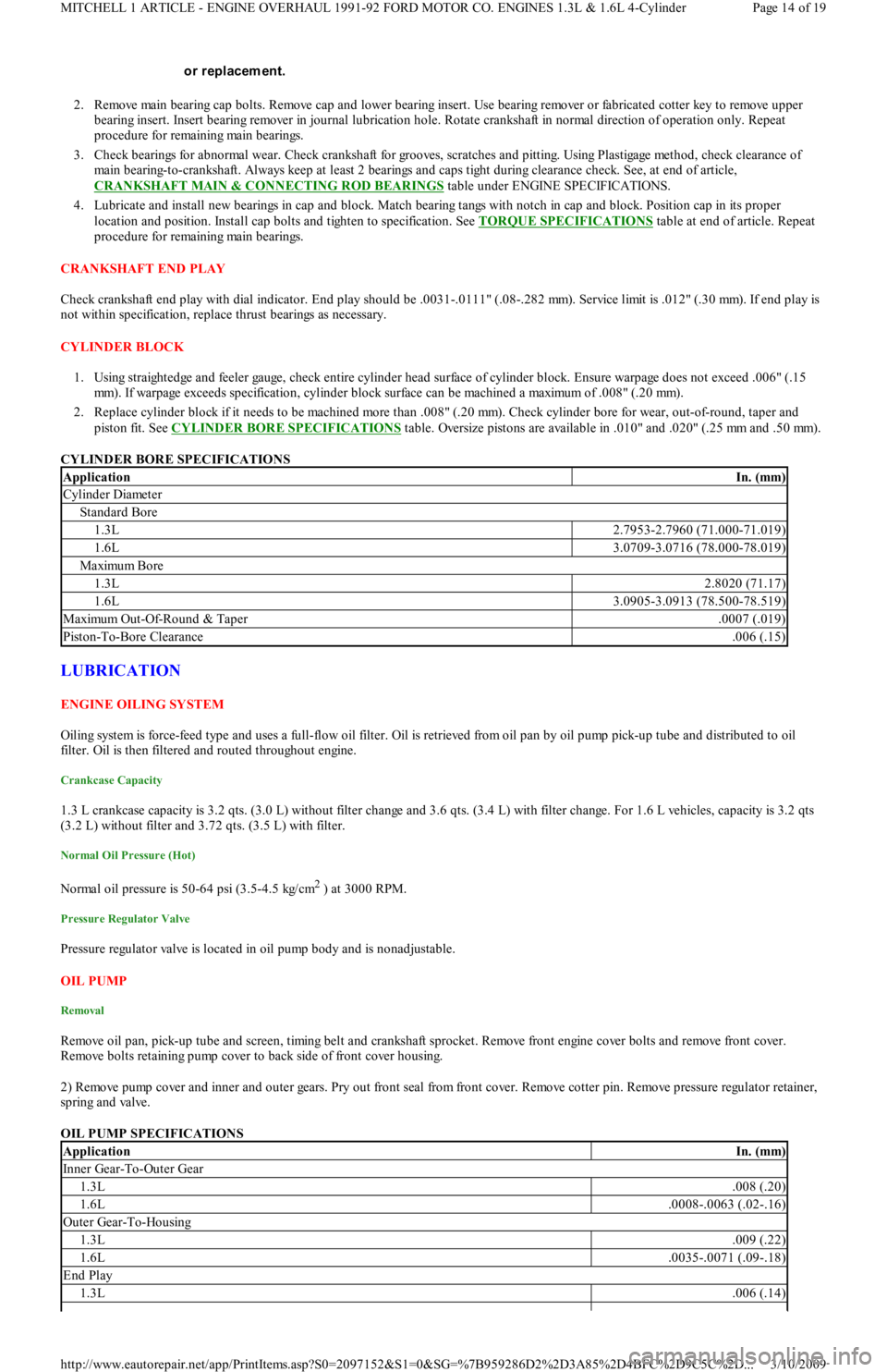
piston fit. See CYLINDER BORE SPECIFICATIONS
table. Oversize pistons are available in .010" and .020" (.25 mm and .50 mm).
CYLINDER BORE SPECIFICATIONS
LUBRICATION
ENGINE OILING SYSTEM
Oiling system is force-feed type and uses a full-flow oil filter. Oil is retrieved from oil pan by oil pump pick-up tube and distributed to oil
filter. Oil is then filtered and routed throughout engine.
Crankcase Capacity
1.3 L crankcase capacity is 3.2 qts. (3.0 L) without filter change and 3.6 qts. (3.4 L) with filter change. For 1.6 L vehicles, capacity is 3.2 qts
(3.2 L) without filter and 3.72 qts. (3.5 L) with filter.
Normal Oil Pressure (Hot)
Normal oil pressure is 50-64 psi (3.5-4.5 kg/cm2 ) at 3000 RPM.
Pressure Regulator Valve
Pressure regulator valve is located in oil pump body and is nonadjustable.
OIL PUMP
Removal
Remove oil pan, pick-up tube and screen, timing belt and crankshaft sprocket. Remove front engine cover bolts and remove front cover.
R e mo ve b o l t s r e t a in in g p u mp c o ve r t o b a c k sid e o f fr o n t c o ve r h o u sin g.
2) Remove pump cover and inner and outer gears. Pry out front seal from front cover. Remove cotter pin. Remove pressure regulator retainer,
spring and valve.
OIL PUMP SPECIFICATIONS or replacem ent.
ApplicationIn. (mm)
Cylinder Diameter
Standard Bore
1.3L2.7953-2.7960 (71.000-71.019)
1.6L3.0709-3.0716 (78.000-78.019)
Maximu m Bo re
1.3L2.8020 (71.17)
1.6L3.0905-3.0913 (78.500-78.519)
Maximu m Ou t -Of-Ro u n d & Tap er.0007 (.019)
Piston-To-Bore Clearance.006 (.15)
ApplicationIn. (mm)
Inner Gear-To-Outer Gear
1.3L.008 (.20)
1.6L.0008-.0063 (.02-.16)
Outer Gear-To-Housing
1.3L.009 (.22)
1.6L.0035-.0071 (.09-.18)
End Play
1.3L.006 (.14)
Page 14 of 19 MITCHELL 1 ARTICLE - ENGINE OVERHAUL 1991-92 FORD MOTOR CO. ENGINES 1.3L & 1.6L 4-Cylinder
3/10/2009 http://www.eautorepair.net/app/PrintItems.asp?S0=2097152&S1=0&SG=%7B959286D2%2D3A85%2D4BFC%2D9C5C%2D
...
Page 211 of 454
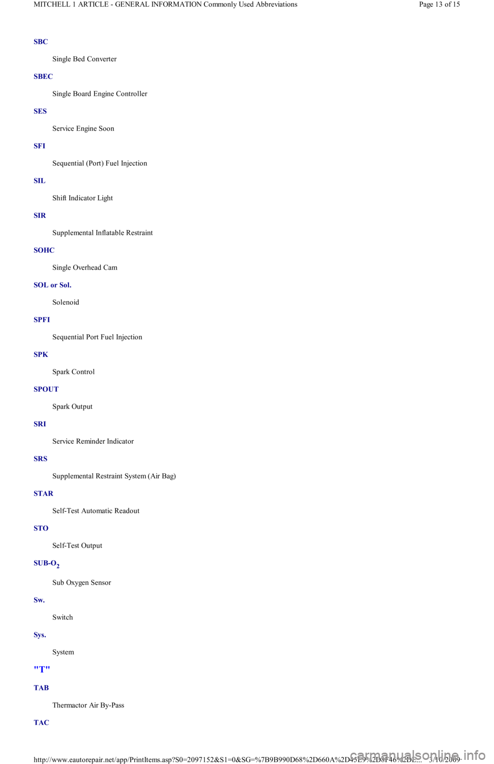
SBC
Single Bed Converter
SBEC
Single Board Engine Controller
SES
Service Engine Soon
SFI
Sequential (Port) Fuel Injection
SIL
Shift Indicator Light
SIR
Supplemental Inflatable Restraint
SOHC
Single Overhead Cam
SOL or Sol.
Solenoid
SPFI
Sequential Port Fuel Injection
SPK
Spark Control
SPOUT
Spark Output
SRI
Service Reminder Indicator
SRS
Supplemental Restraint System (Air Bag)
STAR
Self-Test Automatic Readout
STO
Self-Test Output
SUB-O
2
Sub Oxygen Sensor
Sw.
Switch
Sys.
System
"T"
TAB
Thermactor Air By-Pass
TAC
Page 13 of 15 MITCHELL 1 ARTICLE - GENERAL INFORMATION Commonly Used Abbreviations
3/10/2009 http://www.eautorepair.net/app/PrintItems.asp?S0=2097152&S1=0&SG=%7B9B990D68%2D660A%2D45E9%2D8F46%2DE
...
Page 272 of 454
carburetor. As the exhaust gas quickly warms the intake mixture, distribution is improved. This results in better cold engine driveability,
shorter choke periods and lower emissions.
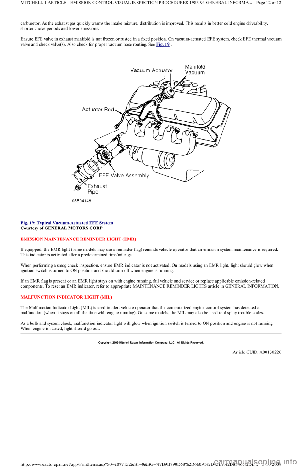
Ensure EFE valve in exhaust manifold is not frozen or rusted in a fixed position. On vacuum-actuated EFE system, check EFE thermal vacuu
m
valve and check valve(s). Also check for proper vacuum hose routing. See Fig. 19
.
Fig. 19: Typical Vacuum
-Actuated EFE System
Courtesy of GENERAL MOTORS CORP.
EMISSION MAINTENANCE REMINDER LIGHT (EMR)
If equipped, the EMR light (some models may use a reminder flag) reminds vehicle operator that an emission system maintenance is required.
This indicator is activated after a predetermined time/mileage.
When performing a smog check inspection, ensure EMR indicator is not activated. On models using an EMR light, light should glow when
ignition switch is turned to ON position and should turn off when engine is running.
If an EMR flag is present or an EMR light stays on with engine running, fail vehicle and service or replace applicable emission-related
components. To reset an EMR indicator, refer to appropriate MAINTENANCE REMINDER LIGHTS article in GENERAL INFORMATION.
MALFUNCTION INDICATOR LIGHT (MIL)
The Malfunction Indicator Light (MIL) is used to alert vehicle operator that the computerized engine control system has detected a
malfunction (when it stays on all the time with engine running). On some models, the MIL may also be used to display trouble codes.
As a bulb and system check, malfunction indicator light will glow when ignition switch is turned to ON position and engine is not running.
When engine is started, light should go out.
Copyr ight 2009 Mitchell Repair Information Company, LLC. All Rights Reserved.
Article GUID: A00130226
Page 12 of 12 MITCHELL 1 ARTICLE - EMISSION CONTROL VISUAL INSPECTION PROCEDURES 1983-93 GENERAL INFORMA...
3/10/2009 http://www.eautorepair.net/app/PrintItems.asp?S0=2097152&S1=0&SG=%7B9B990D68%2D660A%2D45E9%2D8F46%2DE
...
Page 334 of 454
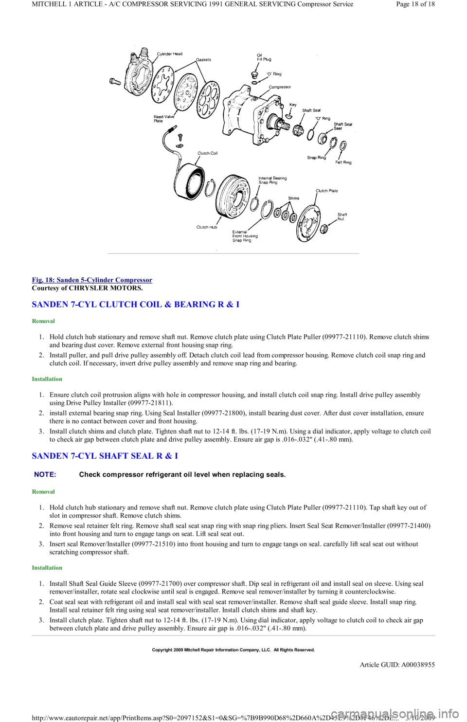
Fig. 18: Sanden 5
-Cylinder Compressor
Courtesy of CHRYSLER MOTORS.
SANDEN 7-CYL CLUTCH COIL & BEARING R & I
Removal
1. Hold clutch hub stationary and remove shaft nut. Remove clutch plate using Clutch Plate Puller (09977-21110). Remove clutch shims
and bearing dust cover. Remove external front housing snap ring.
2. Install puller, and pull drive pulley assembly off. Detach clutch coil lead from compressor housing. Remove clutch coil snap ring and
clutch coil. If necessary, invert drive pulley assembly and remove snap ring and bearing.
Installation
1. Ensure clutch coil protrusion aligns with hole in compressor housing, and install clutch coil snap ring. Install drive pulley assembly
using Drive Pulley Installer (09977-21811).
2. install external bearing snap ring. Using Seal Installer (09977-21800), install bearing dust cover. After dust cover installation, ensure
there is no contact between cover and front housing.
3. Install clutch shims and clutch plate. Tighten shaft nut to 12-14 ft. lbs. (17-19 N.m). Using a dial indicator, apply voltage to clutch coil
to check air gap between clutch plate and drive pulley assembly. Ensure air gap is .016-.032" (.41-.80 mm).
SANDEN 7-CYL SHAFT SEAL R & I
Removal
1. Hold clutch hub stationary and remove shaft nut. Remove clutch plate using Clutch Plate Puller (09977-21110). Tap shaft key out of
slot in compressor shaft. Remove clutch shims.
2. Remove seal retainer felt ring. Remove shaft seal seat snap ring with snap ring pliers. Insert Seal Seat Remover/Installer (09977-21400)
into front housing and turn to engage tangs on seat. Lift seal seat out.
3. Insert seal Remover/Installer (09977-21510) into front housing and turn to engage tangs on seal. carefully lift seal seat out without
scratching compressor shaft.
Installation
1. Install Shaft Seal Guide Sleeve (09977-21700) over compressor shaft. Dip seal in refrigerant oil and install seal on sleeve. Using seal
remover/installer, rotate seal clockwise until seal is engaged. Remove seal remover/installer by turning it counterclockwise.
2. Coat seal seat with refrigerant oil and install seal with seal seat remover/installer. Remove shaft seal guide sleeve. Install snap ring.
Install seal retainer felt ring using seal seat remover/installer. Install clutch shims and shaft key.
3. Install clutch plate. Tighten shaft nut to 12-14 ft. lbs. (17-19 N.m). Using dial indicator, apply voltage to clutch coil to check air gap
between clutch plate and drive pulley assembly. Ensure air gap is .016-.032" (.41-.80 mm).
NOTE:Check com pressor refrigerant oil level when replacing seals.
Copyr ight 2009 Mitchell Repair Information Company, LLC. All Rights Reserved.
Article GUID: A00038955
Page 18 of 18 MITCHELL 1 ARTICLE - A/C COMPRESSOR SERVICING 1991 GENERAL SERVICING Compressor Service
3/10/2009 http://www.eautorepair.net/app/PrintItems.asp?S0=2097152&S1=0&SG=%7B9B990D68%2D660A%2D45E9%2D8F46%2DE
...
Page 370 of 454
BRAKE PAD WEAR INDICATOR
CATALYTIC CONVERTER
COOLANT (PROPYLENE-GLYCOL FORMULATIONS)
ELECTROSTATIC DISCHARGE SENSITIVE (ESD) PARTS
ENGINE OIL
FUEL PUMP SHUTOFF SWITCH
This switch stops flow of fuel to engine after a collision. The impact does not have to be great for switch to be triggered. Switch must be reset
after collision. Switch is located under left rear speaker in luggage compartment. Press button to reset switch.
FUEL SYSTEM SERVICE
HALOGEN BULBS
PASSIVE RESTRAINTS
RADIATOR CAP
RADIATOR FAN
WARRANTY INFORMATION
BASIC NEW CAR LIMITED WARRANTY
All parts of the vehicle, except tires, are covered against defects in factory-supplied materials and workmanship for 12 months or 12,000 miles, CAUT ION: Indicator will cause a squealing or scraping noise, warning that brake pads need replacem ent.
CAUT ION: Continued operation of vehicle with a severe m alfunction could cause converter to overheat, resulting
in possible dam age to converter and vehicle.
CAUT ION: T o avoid possible dam age to vehicle use only ethylene-glycol based coolants with a m ixture ratio from
44-68% anti-freeze. DO NOT use 100% anti-freeze as it will cause the form ation of cooling system
deposits. T his results in coolant tem peratures of over 300° F (149°C) which can m elt plastics. 100% anti-
freeze has a freeze point of only -8° F (-22°C).
CAUT ION: Propylene-Glycol Mixtures has a sm aller tem perature range than Ethylene-Glycol. T he tem perature
range (freeze-boil) of a 50/50 Anti-Freeze/Water Mix is as follows: Propylene-Glycol -26° F (-32°C) - 257° F
(125°C) Ethylene-Glycol -35° F (-37°C) - 263° F (128°C)
CAUT ION: Propylene-Glycol/Ethylene-Glycol Mixtures can cause the destabilization of various corrosion inhibitors.
Also Propylene-Glycol/Ethylene-Glycol has a different specific gravity than Ethylene-Glycol coolant,
which will result in inaccurate freeze point calculations.
WARNING:Many solid state electrical com ponents can be dam aged by static electricity (ESD). Som e will display a
warning label, but m any will not. Discharge personal static electricity by touching a m etal ground point
on the vehicle prior to servicing any ESD sensitive com ponent.
CAUT ION: Never use non-detergent or straight m ineral oil.
WARNING:Relieve fuel system pressure prior to servicing any fuel system com ponent (fuel injection m odels).
WARNING:Halogen bulbs contain pressurized gas which m ay explode if overheated. DO NOT touch glass portion
of bulb with bare hands. Eye protection should be worn when handling or working around halogen
bulbs.
CAUT ION: Before operating vehicle, securely fasten passive shoulder restraints to the em ergency release buckles.
T he buckle fits in only one way. Ensure to position it properly.
CAUT ION: Always disconnect the fan m otor when working near the radiator fan. T he fan is tem perature controlled
and could start at any tim e even when the ignition key is in the OFF position. DO NOT loosen or rem ove
radiator cap when cooling system is hot.
WARNING:Keep hands away from radiator fan. Fan is controlled by a therm ostatic switch which m ay com e on or
run for up to 15 m inutes even after engine is turned off.
CAUT ION: Due to the different warranties offered in various regions and the variety of after-m arket extended
warranties available, please refer to the warranty package that cam e with the vehicle to verify all
warranty options.
Page 6 of 9 MITCHELL 1 ARTICLE - MAINTENANCE INFORMATION 1988-93 MAINTENANCE Ford Motor Co. Maintenance Inform...
3/10/2009 http://www.eautorepair.net/app/PrintItems.asp?S0=2097152&S1=0&SG=%7B9B990D68%2D660A%2D45E9%2D8F46%2DE
...
Page 374 of 454
Back To Article
SERVICE INDICATOR & WARNING LIGHTS
1988-92 MAINT ENANCE Ford Motor Co. Service Indicator & Warning Lights
SERVICE INDICATOR & WARNING LIGHTS
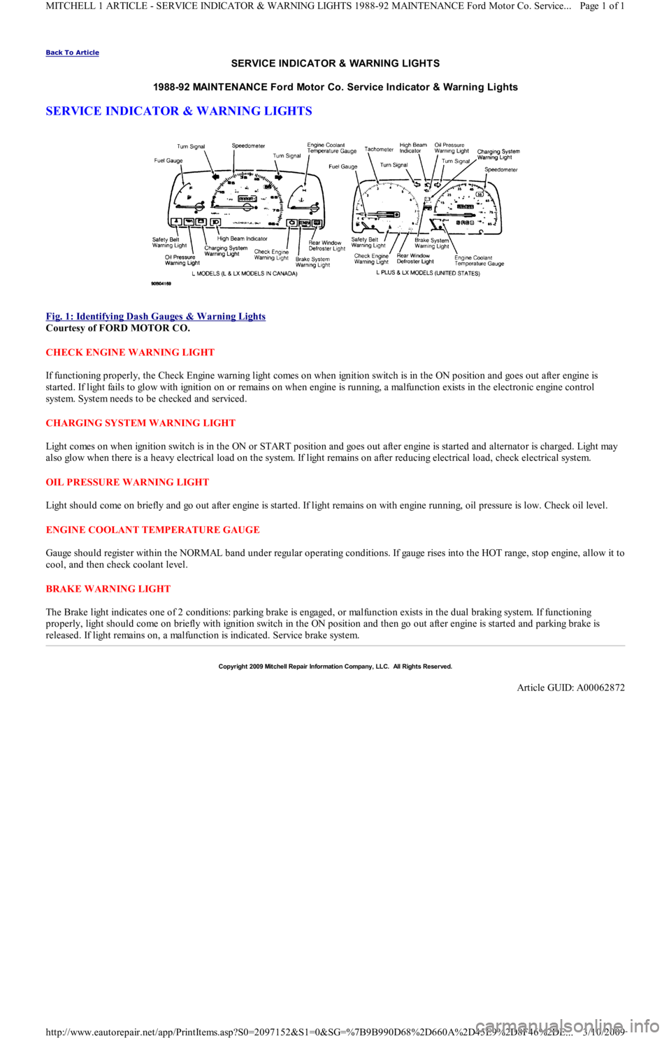
Fig. 1: Identifying Dash Gauges & W arning Lights
Courtesy of FORD MOTOR CO.
CHECK ENGINE WARNING LIGHT
If functioning properly, the Check Engine warning light comes on when ignition switch is in the ON position and goes out after engine is
started. If light fails to glow with ignition on or remains on when engine is running, a malfunction exists in the electronic engine control
system. System needs to be checked and serviced.
CHARGING SYSTEM WARNING LIGHT
Light comes on when ignition switch is in the ON or START position and goes out after engine is started and alternator is charged. Light may
also glow when there is a heavy electrical load on the system. If light remains on after reducing electrical load, check electrical system.
OIL PRESSURE WARNING LIGHT
Light should come on briefly and go out after engine is started. If light remains on with engine running, oil pressure is low. Check oil level.
ENGINE COOLANT TEMPERATURE GAUGE
Gauge should register within the NORMAL band under regular operating conditions. If gauge rises into the HOT range, stop engine, allow it to
cool, and then check coolant level.
BRAKE WARNING LIGHT
The Brake light indicates one of 2 conditions: parking brake is engaged, or malfunction exists in the dual braking system. If functioning
properly, light should come on briefly with ignition switch in the ON position and then go out after engine is started and parking brake is
released. If light remains on, a malfunction is indicated. Service brake system.
Copyr ight 2009 Mitchell Repair Information Company, LLC. All Rights Reserved.
Article GUID: A00062872
Page 1 of 1 MITCHELL 1 ARTICLE - SERVICE INDICATOR & WARNING LIGHTS 1988-92 MAINTENANCE Ford Motor Co. Service
...
3/10/2009 http://www.eautorepair.net/app/PrintItems.asp?S0=2097152&S1=0&SG=%7B9B990D68%2D660A%2D45E9%2D8F46%2DE
...