timing belt FORD FESTIVA 1991 Service Manual
[x] Cancel search | Manufacturer: FORD, Model Year: 1991, Model line: FESTIVA, Model: FORD FESTIVA 1991Pages: 454, PDF Size: 9.53 MB
Page 104 of 454
1. Position new gasket on exhaust manifold, and install turbocharger onto studs. Install 4 retaining nuts and tighten to specification. See
TORQUE SPECIFICATIONS
table at end of article.
2. Remove oil supply line from turbocharger. Position new (2-piece) exhaust gasket on cylinder head with heavy gasket installed first .
Carefully position turbocharger assembly in engine compartment and slide exhaust manifold on studs. Position heater tube bracket onto
exhaust stud. Install 11 retaining nuts onto exhaust manifold and tighten to specification. See TORQUE SPECIFICATIONS
table at
end of article. Tighten heater tube clamp bolt securely.
3. Raise vehicle. Position new gasket and install 2 retaining bolts on heater tube outlet. Install 2 retaining bolts into turbocharger support
bracket and tighten bolts to specification.
4. Connect coolant return hose. Connect oil return hose and secure with clamp. Position exhaust pipe onto turbocharger, and start nuts
and washers. Install 2 retaining bolts on exhaust hanger at engine. Slide on 2 rubber exhaust hangers at catalytic converter. Tighten
exhaust pipe retaining nuts to specification. Lower vehicle.
5. Install retaining bolt and brass washers on oil supply line, carefully position oil line into vehicle and hand-start bolt into engine block.
Connect and finger tighten oil line to turbocharger. Tighten oil line bolt and oil supply line on turbocharger to specification.
6. Connect coolant supply hose. Position air cleaner duct tube on turbocharger and tighten clamp. Install 2 screws retaining air cleaner
duct tube. Position power steering pump bracket on engine, and install 2 retaining bolts and one retaining nut. Tighten to specification.
Position power steering pump on mounting bracket, and install though bolt and adjuster. Connect lower radiator hose. Install power
steering belt. Position upper heat shield and install 2 retaining bolts finger tight.
7. Position lower heat shield and install three retaining bolts finger tight. Tighten all heat shield bolts to specification. Connect O2 sensor
and install connector into its retaining clip. See TORQUE SPECIFICATIONS
table at end of article. Position intercooler hose on
turbocharger and secure with clamp. Install throttle body air intake tube. Connect negative battery cable. Refill cooling system.
CYLINDER HEAD
Removal (1.3L)
1. Disconnect battery ground cable. Mark and disconnect fuel lines at fuel pump. Remove accessory belts, water pump pulley, crankshaft
pulley, timing belt covers, timing belt tensioner, timing belt, valve cover and exhaust and intake manifolds. Drain cooling system.
2. Mark and remove electrical connectors and vacuum hoses. Remove spark plug wires from spark plugs, and remove spark plugs. Remove
distributor cap. Disconnect vacuum hoses and distributor wiring.
3. Index distributor-to-mount position and remove hold-down bolt. Remove distributor assembly. Remove engine ground strap. Remove
front and rear engine lifting hooks. Remove upper radiator hose, by-pass hose and bracket.
4. Remove bolts retaining rocker arm shaft. Remove rocker arm assemblies. Remove cylinder head bolts. Remove head and gasket.
Inspection (1.3L)
1. Thoroughly clean and check gasket mating surface of cylinder head and block. Check cylinder for cracks, nicks, burrs or damage. Using
a straightedge and feeler gauge, check warpage over entire gasket area. Ensure cylinder head and/or block warpage does not
exceed .006" (.15 mm).
2. If warpage exceeds .006" (.15 mm), machine cylinder head and/or block gasket surface. Maximum machining allowed is .008" (.20 mm).
If more machining is required, replace block and/or cylinder head.
Installation (1.3L)
1. Place new head gasket properly on block. Carefully place cylinder head in position on block. Install head bolts. Tighten bolts in
sequence and in 2 steps. See Fig. 1
.
2. While tightening rocker arm shaft, slide shaft springs away from retaining bolt to prevent pinching springs. Tighten rocker arm shaft bolts
in sequence and to specification. See Fig. 5
. To complete installation, reverse removal procedure. Tighten all bolts/nuts to
specification. Fill all fluids to proper levels. NOTE:T urbocharger-to-exhaust m anifold m ounting nuts are of special quality. Ensure correct nuts are
used.
NOTE:Ensure one brass washer is positioned on each side of oil line fitting.
NOTE:Feed O2 sensor wire through upper heat shield. Install wire retainer under LH bolt.
NOTE:If turbocharger was replaced: Disconnect ignition coil, crank engine for 20 seconds, connect ignition
coil, start engine and run at idle for 30 seconds and check for leaks.
NOTE:If original tim ing belt is being reused, m ark direction of rotation for installation reference.
Page 4 of 19 MITCHELL 1 ARTICLE - ENGINE OVERHAUL 1991-92 FORD MOTOR CO. ENGINES 1.3L & 1.6L 4-Cylinder
3/10/2009 http://www.eautorepair.net/app/PrintItems.asp?S0=2097152&S1=0&SG=%7B959286D2%2D3A85%2D4BFC%2D9C5C%2D
...
Page 105 of 454
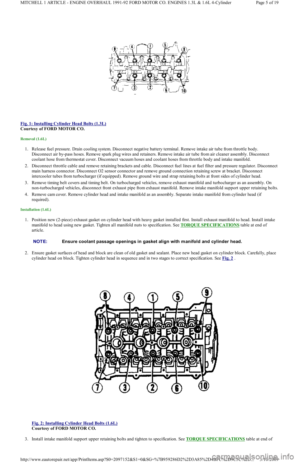
Fig. 1: Installing Cylinder Head Bolts (1.3L)
Courtesy of FORD MOTOR CO.
Removal (1.6L)
1. Release fuel pressure. Drain cooling system. Disconnect negative battery terminal. Remove intake air tube from throttle body.
Disconnect air by-pass hoses. Remove spark plug wires and retainers. Remove intake air tube from air cleaner assembly. Disconnect
coolant hose from thermostat cover. Disconnect vacuum hoses and coolant hoses from throttle body and intake manifold.
2. Disconnect throttle cable and remove retaining brackets and cable. Disconnect fuel lines at fuel filter and pressure regulator. Disconnect
main harness connector. Disconnect O2 sensor connector and remove ground connection retaining screw at bracket. Disconnect
intercooler tubes from turbocharger (if equipped). Remove ground wire and strap retaining bolts at front sides of cylinder head.
3. Remove timing belt covers and timing belt. On turbocharged vehicles, remove exhaust manifold and turbocharger as an assembly. On
non-turbocharged vehicles, disconnect front exhaust pipe from exhaust manifold. Remove intake manifold support upper retaining bolts.
4. Remove cam cover. Remove cylinder head and intake manifold as an assembly. Separate intake manifold from cylinder head (if
required).
Installation (1.6L)
1. Position new (2-piece) exhaust gasket on cylinder head with heavy gasket installed first. Install exhaust manifold to head. Install intake
manifold to head using new gasket. Tighten all manifold nuts to specification. See TORQUE SPECIFICATIONS
table at end of
article.
2. Ensure gasket surfaces of head and block are clean of old gasket and sealant. Place new head gasket on cylinder block. Carefully, place
cylinder head on block. Tighten cylinder head in sequence and in two stages to correct specification. See Fig. 2
.
Fig. 2: Installing Cylinder Head Bolts (1.6L)
Courtesy of FORD MOTOR CO.
3. Install intake manifold support upper retaining bolts and tighten to specification. See TORQUE SPECIFICATIONS
table at end of
NOTE:Ensure coolant passage openings in gasket align with m anifold and cylinder head.
Page 5 of 19 MITCHELL 1 ARTICLE - ENGINE OVERHAUL 1991-92 FORD MOTOR CO. ENGINES 1.3L & 1.6L 4-Cylinder
3/10/2009 http://www.eautorepair.net/app/PrintItems.asp?S0=2097152&S1=0&SG=%7B959286D2%2D3A85%2D4BFC%2D9C5C%2D
...
Page 106 of 454
article. Install timing belt and covers. Install cam cover. On non-turbo engines, connect front exhaust pipe to exhaust manifold. Tighten
nuts to specification.
4. On turbocharged engines, install exhaust manifold and turbocharger assembly. Install ground wire and strap to cylinder head with
retaining bolts. Connect intercooler tubes (if equipped). Connect O2 sensor connector, and install ground wires to bracket on cylinder
head with retaining screw. Connect main engine harness connector. Connect fuel lines to fuel filter and pressure regulator. Install
throttle cable and retaining brackets.
5. Install coolant hoses and vacuum lines to intake manifold and throttle body. Install coolant hose to thermostat cover. Install intake air
tube to air cleaner. Install spark plug wires and retainers. Install intake air tube to throttle body, and connect by-pass hoses. Fill cooling
system. Connect negative battery terminal. Start engine, check for leaks and system operation.
TIMING BELT COVER
Removal & Installation (1.3L)
Remove accessory belts. Remove water pump pulley. Remove crankshaft damper. Remove bolts retaining upper and lower cover halves to
engine front. Remove both covers. To install, reverse removal procedure.
Removal & Installation (1.6L)
Raise vehicle on hoist. Remove RF tire and wheel assembly. Remove RF splash guard. Lower vehicle. Remove spark plugs and set camsh aft
timing to TDC No. 1 cylinder. Remove oil dipstick. Remove water pump pulley. Remove crankshaft pulley, damper and baffle plate. Remove
upper timing belt cover. Remove center and lower timing belt covers. To install, reverse removal procedure.
TIMING BELT
Removal (1.3L)
Remove accessory belts, water pump pulley, crankshaft damper and upper and lower timing belt covers. Mark timing belt direction of rotation
for installation reference. Remove timing belt tensioner pulley bolt. Remove tensioner pulley, spring and spring cover. Remove timing belt.
Installation (1.3L)
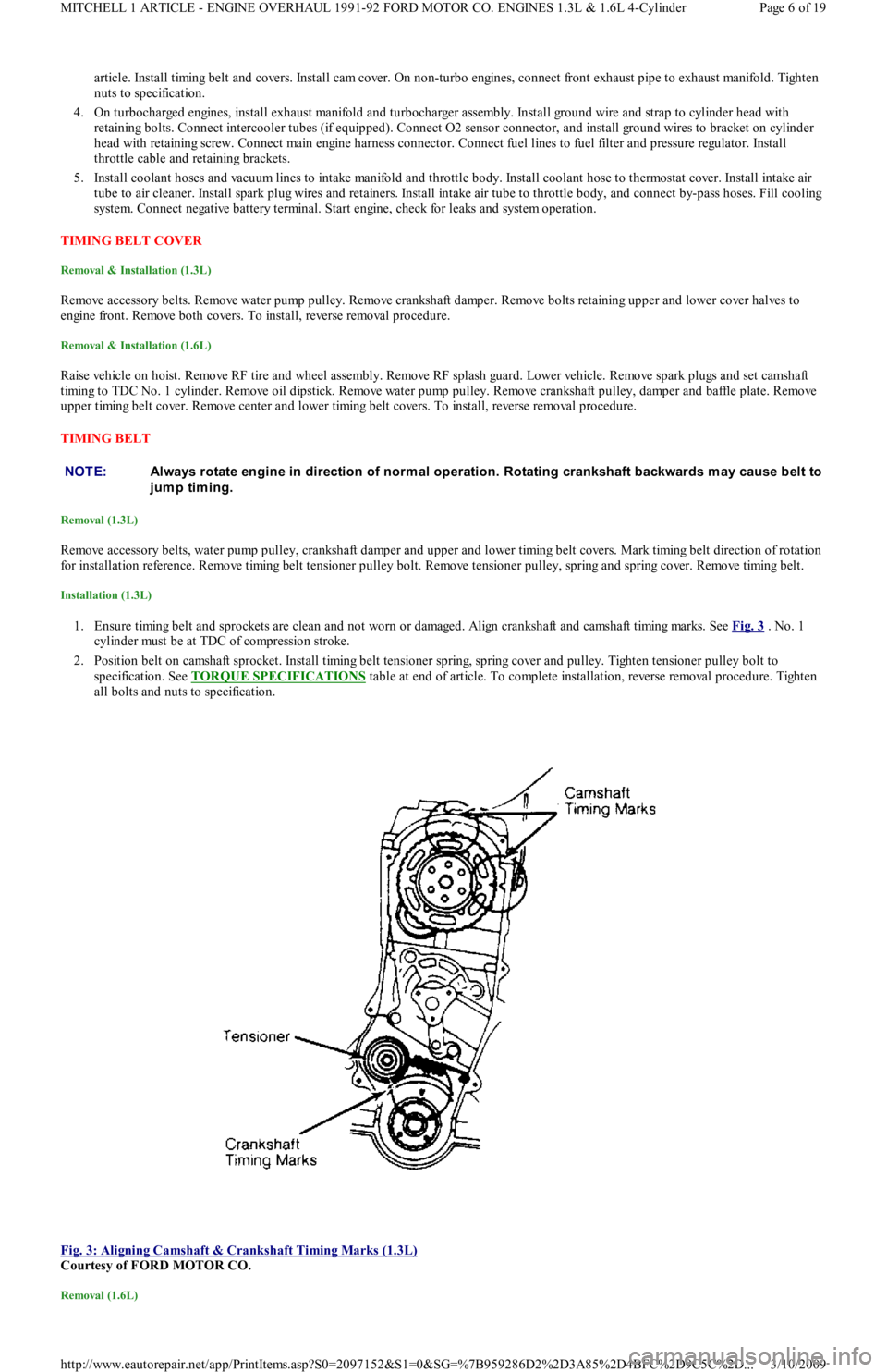
1. Ensure timing belt and sprockets are clean and not worn or damaged. Align crankshaft and camshaft timing marks. See Fig. 3 . No. 1
cylinder must be at TDC of compression stroke.
2. Position belt on camshaft sprocket. Install timing belt tensioner spring, spring cover and pulley. Tighten tensioner pulley bolt to
specification. See TORQUE SPECIFICATIONS
table at end of article. To complete installation, reverse removal procedure. Tighten
all bolts and nuts to specification.
Fig. 3: Aligning Camshaft & Crankshaft Timing Marks (1.3L)
Courtesy of FORD MOTOR CO.
Removal (1.6L)
NOTE:Always rotate engine in direction of norm al operation. Rotating crankshaft backwards m ay cause belt to
jump timing.
Page 6 of 19 MITCHELL 1 ARTICLE - ENGINE OVERHAUL 1991-92 FORD MOTOR CO. ENGINES 1.3L & 1.6L 4-Cylinder
3/10/2009 http://www.eautorepair.net/app/PrintItems.asp?S0=2097152&S1=0&SG=%7B959286D2%2D3A85%2D4BFC%2D9C5C%2D
...
Page 107 of 454
Remove timing belt covers, See TIMING BELT COVER procedure to remove timing belt from this engine.
Installation (1.6L)
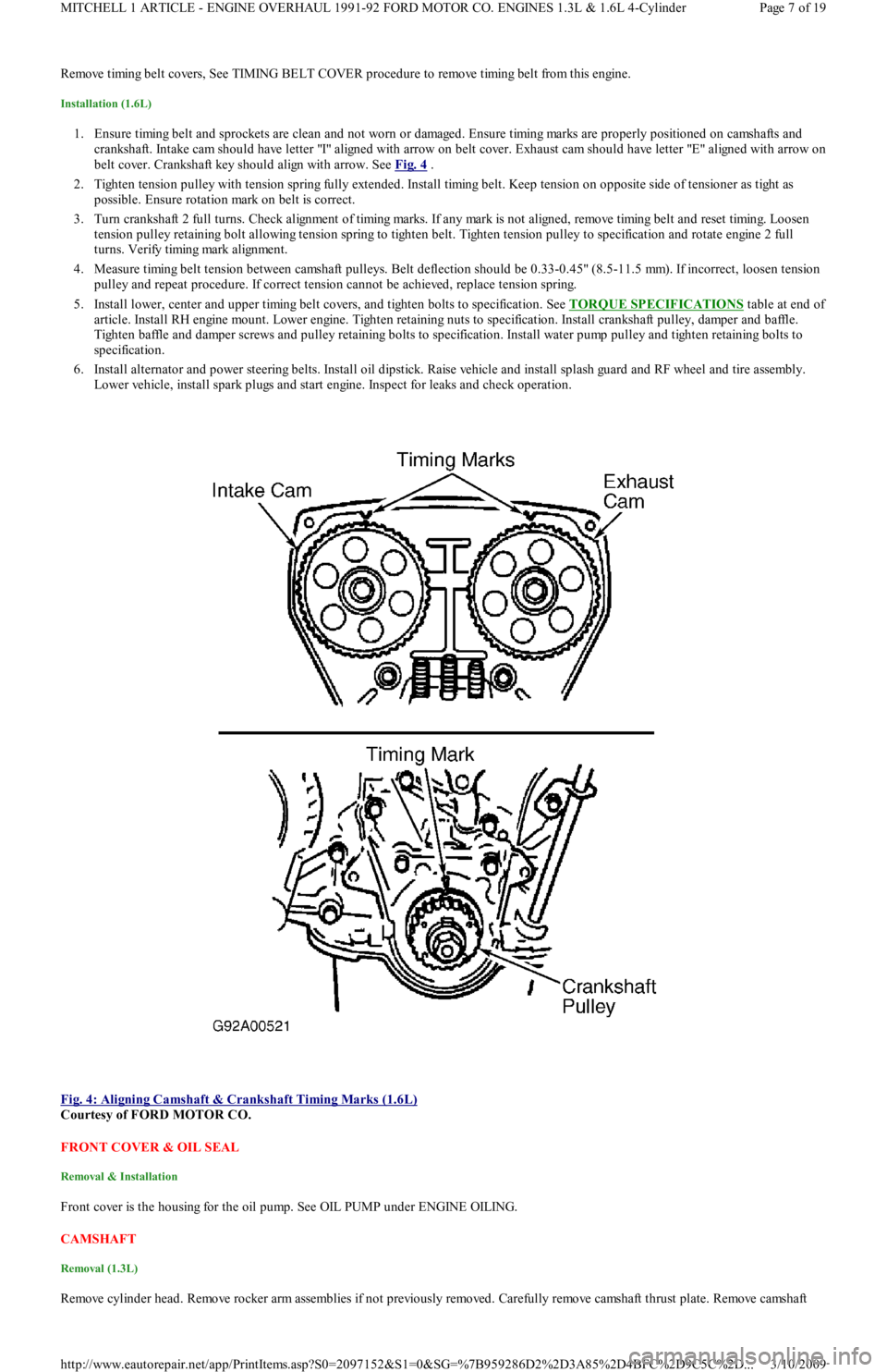
1. Ensure timing belt and sprockets are clean and not worn or damaged. Ensure timing marks are properly positioned on camshafts and
crankshaft. Intake cam should have letter "I" aligned with arrow on belt cover. Exhaust cam should have letter "E" aligned with arrow on
belt cover. Crankshaft key should align with arrow. See Fig. 4
.
2. Tighten tension pulley with tension spring fully extended. Install timing belt. Keep tension on opposite side of tensioner as tight as
possible. Ensure rotation mark on belt is correct.
3. Turn crankshaft 2 full turns. Check alignment of timing marks. If any mark is not aligned, remove timing belt and reset timing. Lo o se n
tension pulley retaining bolt allowing tension spring to tighten belt. Tighten tension pulley to specification and rotate engine 2 full
turns. Verify timing mark alignment.
4. Measure timing belt tension between camshaft pulleys. Belt deflection should be 0.33-0.45" (8.5-11.5 mm). If incorrect, loosen tension
pulley and repeat procedure. If correct tension cannot be achieved, replace tension spring.
5. Install lower, center and upper timing belt covers, and tighten bolts to specification. See TORQUE SPECIFICATIONS
table at end of
article. Install RH engine mount. Lower engine. Tighten retaining nuts to specification. Install crankshaft pulley, damper and baffle.
Tighten baffle and damper screws and pulley retaining bolts to specification. Install water pump pulley and tighten retaining bolts to
specification.
6. Install alternator and power steering belts. Install oil dipstick. Raise vehicle and install splash guard and RF wheel and tire assembly.
Lower vehicle, install spark plugs and start engine. Inspect for leaks and check operation.
Fig. 4: Aligning Camshaft & Crankshaft Timing Marks (1.6L)
Courtesy of FORD MOTOR CO.
FRONT COVER & OIL SEAL
Removal & Installation
Front cover is the housing for the oil pump. See OIL PUMP under ENGINE OILING.
CAMSHAFT
Removal (1.3L)
Remove cylinder head. Remove rocker arm assemblies if not previously removed. Carefully remove camshaft thrust plate. Remove camsh aft
Page 7 of 19 MITCHELL 1 ARTICLE - ENGINE OVERHAUL 1991-92 FORD MOTOR CO. ENGINES 1.3L & 1.6L 4-Cylinder
3/10/2009 http://www.eautorepair.net/app/PrintItems.asp?S0=2097152&S1=0&SG=%7B959286D2%2D3A85%2D4BFC%2D9C5C%2D
...
Page 109 of 454
2. Measure camshaft bearing journals and cylinder head bores (with bearing caps in place and torqued to specification). See Fig. 7 .
Subtract camshaft bearing journal O.D. from cylinder head bore I.D. to obtain oil clearance. If clearance is not within specification,
replace head and/or camshaft. See CAMSHAFT SPECIFICATIONS
table under ENGINE SPECIFICATIONS at end of article.
Installation (1.6L)
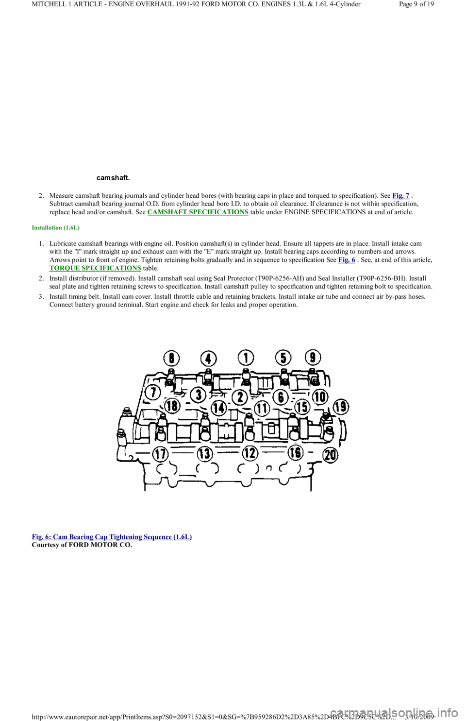
1. Lubricate camshaft bearings with engine oil. Position camshaft(s) in cylinder head. Ensure all tappets are in place. Install intake cam
with the "I" mark straight up and exhaust cam with the "E" mark straight up. Install bearing caps according to numbers and arrows.
Arrows point to front of engine. Tighten retaining bolts gradually and in sequence to specification See Fig. 6
. See, at end of this article,
TORQUE SPECIFICATIONS
table.
2. Install distributor (if removed). Install camshaft seal using Seal Protector (T90P-6256-AH) and Seal Installer (T90P-6256-BH). Install
seal plate and tighten retaining screws to specification. Install camshaft pulley to specification and tighten retaining bolt to specification.
3. Install timing belt. Install cam cover. Install throttle cable and retaining brackets. Install intake air tube and connect air by-pass hoses.
Connect battery ground terminal. Start engine and check for leaks and proper operation.
Fig. 6: Cam Bearing Cap Tightening Sequence (1.6L)
Courtesy of FORD MOTOR CO. cam shaft.
Page 9 of 19 MITCHELL 1 ARTICLE - ENGINE OVERHAUL 1991-92 FORD MOTOR CO. ENGINES 1.3L & 1.6L 4-Cylinder
3/10/2009 http://www.eautorepair.net/app/PrintItems.asp?S0=2097152&S1=0&SG=%7B959286D2%2D3A85%2D4BFC%2D9C5C%2D
...
Page 111 of 454
bearing oil seal. To complete installation, reverse removal procedure.
WATER PUMP
Removal & Installation (1.3L)
Remove timing belt. Drain cooling system. Remove lower radiator hose and heater return hose from water pump. Remove water pump
retaining bolts and water pump. Clean gasket mounting surface and replace gasket. To install, reverse removal procedure.
Removal (1.6L)
1. Remove timing belt. See TIMING BELT . Drain cooling system. Remove timing belt tensioner and idler pulleys. Remove oil dipstick
bracket retaining bolt.
2. Remove power steering pump from retaining bracket, leaving hoses attached. Remove power steering bracket and position power
steering pump to one side. Remove water pump outlet. Remove water pump retaining bolts and water pump.
Installation (1.6L)
1. Clean all gasket surfaces. Transfer rubber belt cover seal to new water pump (if required). Position water pump with new gasket and
install retaining bolts. Install pump outlet with new gasket and "O" ring. See TORQUE SPECIFICATIONS
table at end of article.
2. Install oil dipstick retaining bolt. Install timing belt tensioner and idler pulleys. Install power steering pump bracket. Install power
steering pump. Tighten all bolts and nuts to specification. See TORQUE SPECIFICATIONS
table at end of article.
3. Install timing belt. Fill cooling system. Start engine and check for leaks and proper system function.
OIL PAN
Removal (1.3L)
Disconnect battery ground cable. Raise vehicle and drain engine oil. Remove flywheel housing dust cover. Remove oil pan retaining bolts,
nuts and stiffeners. Rotate crankshaft while removing oil pan. Remove baffle plate from oil pan. Clean gasket mating surfaces thoroughly.
Installation (1.3L)
Ensure gasket surfaces are clean. Apply oil resistant sealer to front and rear engine covers and across joint line of cylinder block.
Removal (1.6L)
1. Raise vehicle and drain engine oil. Remove frame brace retaining bolt. Loosen RH "A" arm front bolt, and pivot brace downward.
Disconnect front exhaust pipe from exhaust manifold (or turbocharger). Remove exhaust pipe bracket retaining bolts. Loosen rubber
exhaust hangers at catalytic converter.
2. Allow exhaust to hang supported by mechanic's wire. Disconnect turbocharger oil return hose (if equipped). Remove oil pan retaining
bolts. Carefully pry oil pan loose from cylinder block.
Installation (1.6L)
1. Clean pan and block gasket surfaces. Apply Gasket Sealant (E3AZ-19562-A) to new front and rear pan seals. Install seals to cylinder
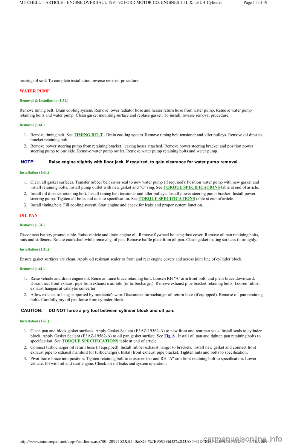
block. Apply Gasket Sealant (E3AZ-19562-A) to oil pan gasket surface. See Fig. 8
. Install oil pan and tighten pan retaining bolts to
specification. See TORQUE SPECIFICATIONS
table at end of article.
2. Connect turbocharger oil return hose (if equipped). Install rubber exhaust hanger to brackets. Install new gasket and connect fro n t
exhaust pipe to exhaust manifold (or turbocharger). Install front exhaust pipe bracket. Tighten nuts and bolts to specification.
3. Pivot frame brace into position. Tighten retaining bolt to crossmember and RH "A" arm front retaining bolt to specification. Lower
vehicle, fill with oil and start engine. Check for oil leaks and system operation. NOTE:Raise engine slightly with floor jack, if required, to gain clearance for water pum p rem oval.
CAUT ION: DO NOT force a pry tool between cylinder block and oil pan.
Page 11 of 19 MITCHELL 1 ARTICLE - ENGINE OVERHAUL 1991-92 FORD MOTOR CO. ENGINES 1.3L & 1.6L 4-Cylinder
3/10/2009 http://www.eautorepair.net/app/PrintItems.asp?S0=2097152&S1=0&SG=%7B959286D2%2D3A85%2D4BFC%2D9C5C%2D
...
Page 114 of 454
2. Remove main bearing cap bolts. Remove cap and lower bearing insert. Use bearing remover or fabricated cotter key to remove upper
bearing insert. Insert bearing remover in journal lubrication hole. Rotate crankshaft in normal direction of operation only. Repeat
procedure for remaining main bearings.
3. Check bearings for abnormal wear. Check crankshaft for grooves, scratches and pitting. Using Plastigage method, check clearance of
main bearing-to-crankshaft. Always keep at least 2 bearings and caps tight during clearance check. See, at end of article,
CRANKSHAFT MAIN & CONNECTING ROD BEARINGS
table under ENGINE SPECIFICATIONS.
4. Lubricate and install new bearings in cap and block. Match bearing tangs with notch in cap and block. Position cap in its proper
location and position. Install cap bolts and tighten to specification. See TORQUE SPECIFICATIONS
table at end of article. Repeat
procedure for remaining main bearings.
CRANKSHAFT END PLAY
Check crankshaft end play with dial indicator. End play should be .0031-.0111" (.08-.282 mm). Service limit is .012" (.30 mm). If end play is
not within specification, replace thrust bearings as necessary.
CYLINDER BLOCK
1. Using straightedge and feeler gauge, check entire cylinder head surface of cylinder block. Ensure warpage does not exceed .006" (.15
mm). If warpage exceeds specification, cylinder block surface can be machined a maximum of .008" (.20 mm).
2. Replace cylinder block if it needs to be machined more than .008" (.20 mm). Check cylinder bore for wear, out-of-round, taper and
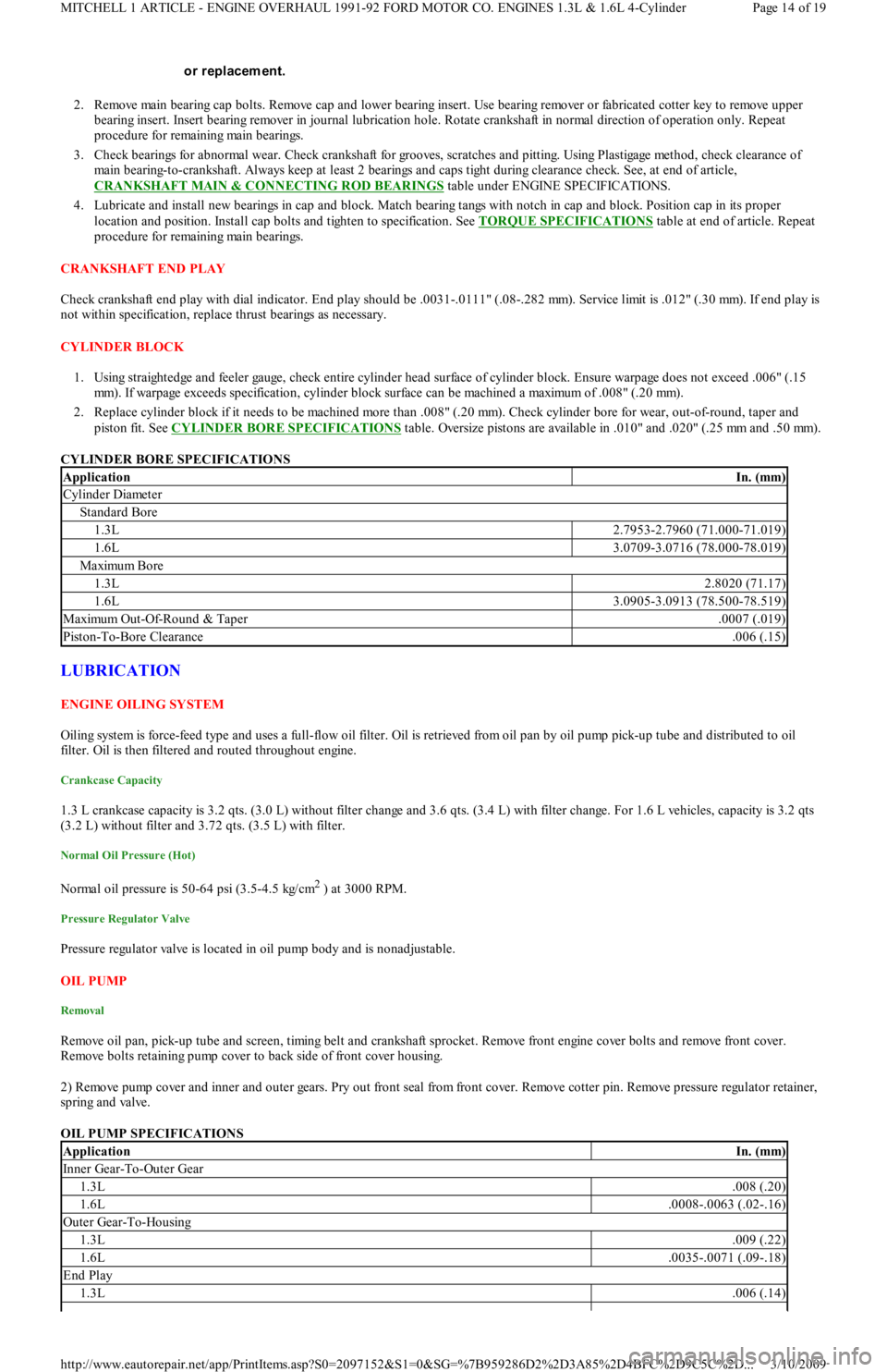
piston fit. See CYLINDER BORE SPECIFICATIONS
table. Oversize pistons are available in .010" and .020" (.25 mm and .50 mm).
CYLINDER BORE SPECIFICATIONS
LUBRICATION
ENGINE OILING SYSTEM
Oiling system is force-feed type and uses a full-flow oil filter. Oil is retrieved from oil pan by oil pump pick-up tube and distributed to oil
filter. Oil is then filtered and routed throughout engine.
Crankcase Capacity
1.3 L crankcase capacity is 3.2 qts. (3.0 L) without filter change and 3.6 qts. (3.4 L) with filter change. For 1.6 L vehicles, capacity is 3.2 qts
(3.2 L) without filter and 3.72 qts. (3.5 L) with filter.
Normal Oil Pressure (Hot)
Normal oil pressure is 50-64 psi (3.5-4.5 kg/cm2 ) at 3000 RPM.
Pressure Regulator Valve
Pressure regulator valve is located in oil pump body and is nonadjustable.
OIL PUMP
Removal
Remove oil pan, pick-up tube and screen, timing belt and crankshaft sprocket. Remove front engine cover bolts and remove front cover.
R e mo ve b o l t s r e t a in in g p u mp c o ve r t o b a c k sid e o f fr o n t c o ve r h o u sin g.
2) Remove pump cover and inner and outer gears. Pry out front seal from front cover. Remove cotter pin. Remove pressure regulator retainer,
spring and valve.
OIL PUMP SPECIFICATIONS or replacem ent.
ApplicationIn. (mm)
Cylinder Diameter
Standard Bore
1.3L2.7953-2.7960 (71.000-71.019)
1.6L3.0709-3.0716 (78.000-78.019)
Maximu m Bo re
1.3L2.8020 (71.17)
1.6L3.0905-3.0913 (78.500-78.519)
Maximu m Ou t -Of-Ro u n d & Tap er.0007 (.019)
Piston-To-Bore Clearance.006 (.15)
ApplicationIn. (mm)
Inner Gear-To-Outer Gear
1.3L.008 (.20)
1.6L.0008-.0063 (.02-.16)
Outer Gear-To-Housing
1.3L.009 (.22)
1.6L.0035-.0071 (.09-.18)
End Play
1.3L.006 (.14)
Page 14 of 19 MITCHELL 1 ARTICLE - ENGINE OVERHAUL 1991-92 FORD MOTOR CO. ENGINES 1.3L & 1.6L 4-Cylinder
3/10/2009 http://www.eautorepair.net/app/PrintItems.asp?S0=2097152&S1=0&SG=%7B959286D2%2D3A85%2D4BFC%2D9C5C%2D
...
Page 115 of 454
Installation
1. Install pressure regulator valve, spring, retainer and new cotter pin. Press a new seal in front cover housing. Install outer and inner gears
in housing. Install pump cover. Coat bolts with Loctite and tighten to specification. See TORQUE SPECIFICATIONS
table at end of
article.
2. Install new gasket and install front cover housing. Install new gasket and install pick-up tube and screen. Tighten all bolts/nuts to
specification. To complete installation, reverse removal procedure.
ENGINE COOLING
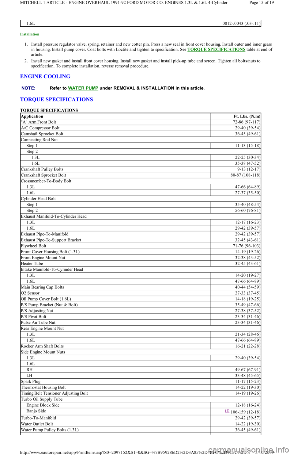
TORQUE SPECIFICATIONS
TORQUE SPECIFICATIONS
1.6L.0012-.0043 (.03-.11)
NOTE:Refer to WAT ER PUMP
under REMOVAL & INSTALLATION in this article.
ApplicationFt. Lbs. (N.m)
"A" Arm Front Bolt72-86 (97-117)
A/C Compressor Bolt29-40 (39-54)
Camshaft Sprocket Bolt36-45 (49-61)
Connecting Rod Nut
Step 111-13 (15-18)
Step 2
1.3L22-25 (30-34)
1.6L35-38 (47-52)
Crankshaft Pulley Bolts9-13 (12-17)
Crankshaft Sprocket Bolt80-87 (108-118)
Crossmember-To-Body Bolt
1.3L47-66 (64-89)
1.6L27-37 (35-50)
Cylinder Head Bolt
Step 135-40 (48-54)
Step 256-60 (76-81)
Exhaust Manifold-To-Cylinder Head
1.3L12-17 (16-23)
1.6L29-42 (39-57)
Exhaust Pipe-To-Manifold29-42 (39-57)
Exhaust Pipe-To-Support Bracket32-45 (43-61)
Flywheel Bolt71-76 (96-103)
Front Cover Housing Bolt (1.3L)14-19 (19-26)
Front Engine Mount Nut32-38 (43-52)
Heater Tube32-45 (43-61)
Intake Manifold-To-Cylinder Head
1.3L14-20 (19-27)
1.6L47-66 (64-89)
Main Bearing Cap Bolts40-44 (54-59)
O2 Sensor27-33 (37-45)
Oil Pump Cover Bolt (1.6L)14-18 (19-25)
P/S Pump Bracket (Nut & Bolt)35-49 (47-66)
P/S Adjusting Nut27-38 (37-52)
P/S Pivot Bolt23-34 (31-46)
Pulse Air Tube Nut23-34 (31-46)
Rear Engine Mount Nut
1.3L21-34 (28-46)
1.6L47-66 (64-89)
Rocker Arm Shaft Bolts16-21 (22-28)
Side Engine Mount Nuts
1.3L29-40 (39-54)
1.6L
RH49-67 (67-91)
LH33-48 (45-65)
Spark Plug11-17 (15-23)
Thermostat Housing Bolt14-22 (19-30)
Timing Belt Tensioner Adjusting Bolt14-19 (19-26)
Turbo Oil Supply Tube
Engine Block Side12-18 (16-24)
Banjo Side(1) 106-159 (12-18)
Turbo-To-Manifold29-42 (39-57)
Water Outlet Bolt14-22 (19-30)
Water Pump Pulley Bolts (1.3L)36-45 (49-61)
Page 15 of 19 MITCHELL 1 ARTICLE - ENGINE OVERHAUL 1991-92 FORD MOTOR CO. ENGINES 1.3L & 1.6L 4-Cylinder
3/10/2009 http://www.eautorepair.net/app/PrintItems.asp?S0=2097152&S1=0&SG=%7B959286D2%2D3A85%2D4BFC%2D9C5C%2D
...
Page 116 of 454
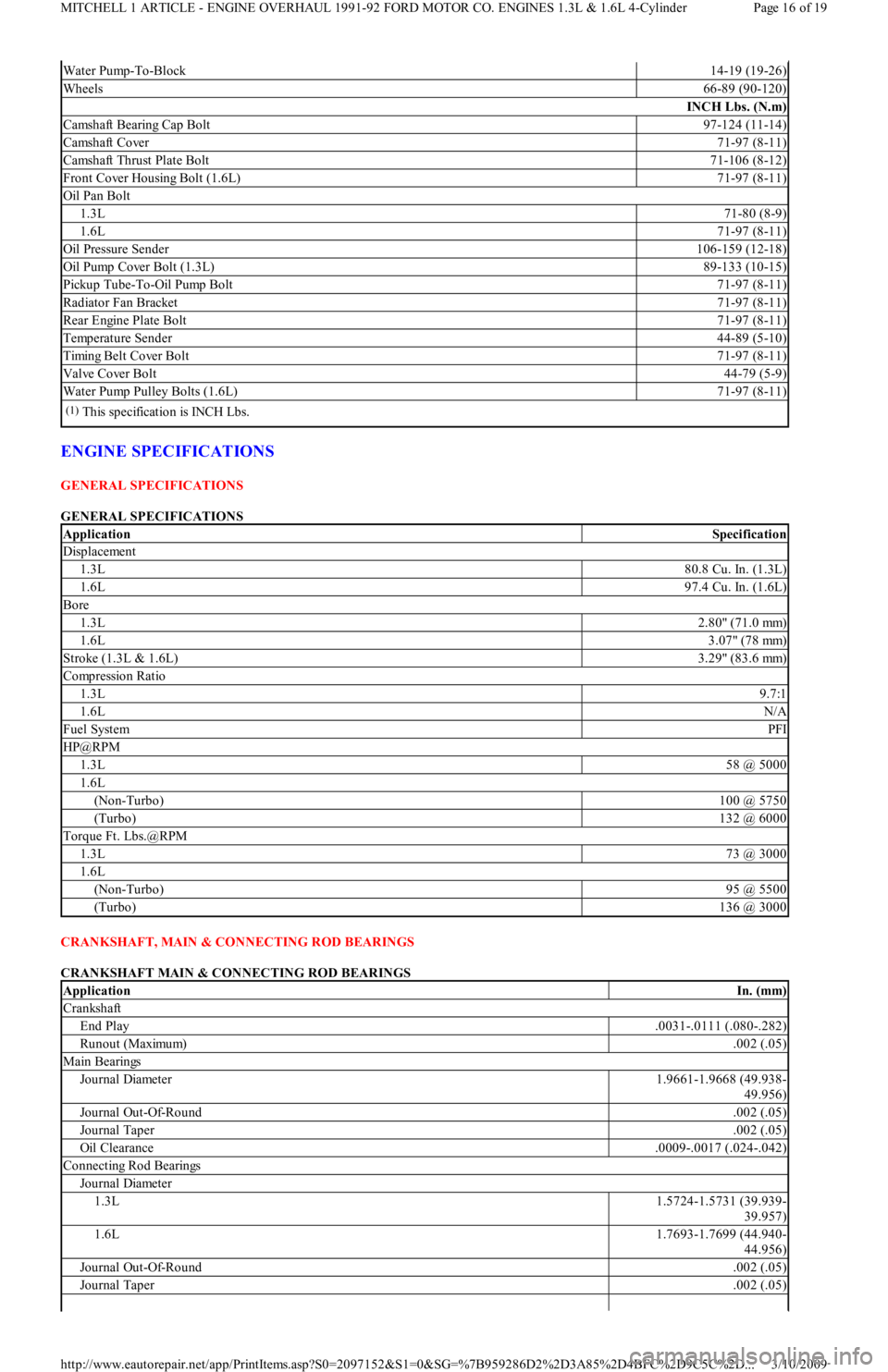
ENGINE SPECIFICATIONS
GENERAL SPECIFICATIONS
GENERAL SPECIFICATIONS
CRANKSHAFT, MAIN & CONNECTING ROD BEARINGS
CRANKSHAFT MAIN & CONNECTING ROD BEARINGS
Water Pump-To-Block14-19 (19-26)
Wheels66-89 (90-120)
INCH Lbs. (N.m)
Camshaft Bearing Cap Bolt97-124 (11-14)
Camshaft Cover71-97 (8-11)
Camshaft Thrust Plate Bolt71-106 (8-12)
Front Cover Housing Bolt (1.6L)71-97 (8-11)
Oil Pan Bolt
1.3L71-80 (8-9)
1.6L71-97 (8-11)
Oil Pressure Sender106-159 (12-18)
Oil Pump Cover Bolt (1.3L)89-133 (10-15)
Pickup Tube-To-Oil Pump Bolt71-97 (8-11)
Radiator Fan Bracket71-97 (8-11)
Rear Engine Plate Bolt71-97 (8-11)
Temperature Sender44-89 (5-10)
Timing Belt Cover Bolt71-97 (8-11)
Valve Cover Bolt44-79 (5-9)
Water Pump Pulley Bolts (1.6L)71-97 (8-11)
(1)This specification is INCH Lbs.
ApplicationSpecification
Displacement
1.3L80.8 Cu. In. (1.3L)
1.6L97.4 Cu. In. (1.6L)
Bore
1.3L2.80" (71.0 mm)
1.6L3.07" (78 mm)
Stroke (1.3L & 1.6L)3.29" (83.6 mm)
Compression Ratio
1.3L9.7:1
1.6LN/A
Fuel SystemPFI
HP@RPM
1.3L58 @ 5000
1.6L
(Non-Turbo)100 @ 5750
(Turbo)132 @ 6000
Torque Ft. Lbs.@RPM
1.3L73 @ 3000
1.6L
(Non-Turbo)95 @ 5500
(Turbo)136 @ 3000
ApplicationIn. (mm)
Crankshaft
End Play.0031-.0111 (.080-.282)
Runout (Maximum).002 (.05)
Main Bearings
Journal Diameter1.9661-1.9668 (49.938-
49.956)
Journal Out-Of-Round.002 (.05)
Journal Taper.002 (.05)
Oil Clearance.0009-.0017 (.024-.042)
Connecting Rod Bearings
Journal Diameter
1.3L1.5724-1.5731 (39.939-
39.957)
1.6L1.7693-1.7699 (44.940-
44.956)
Journal Out-Of-Round.002 (.05)
Journal Taper.002 (.05)
Page 16 of 19 MITCHELL 1 ARTICLE - ENGINE OVERHAUL 1991-92 FORD MOTOR CO. ENGINES 1.3L & 1.6L 4-Cylinder
3/10/2009 http://www.eautorepair.net/app/PrintItems.asp?S0=2097152&S1=0&SG=%7B959286D2%2D3A85%2D4BFC%2D9C5C%2D
...
Page 126 of 454
Back To Article
FORD
1.3L 4-Cylinder
MANUFACTURER'S SUGGESTED SCHEDULED MAINTENANCE
For Aspire, the manufacturer recommends the belt be replaced every 60,000 miles on Federal vehicles, and 105,000 miles on California
vehicles. For Festiva, the manufacturer recommends the belt be replaced every 60,000 miles.
REMOVAL & INSTALLATION
TIMING BELT
Removal
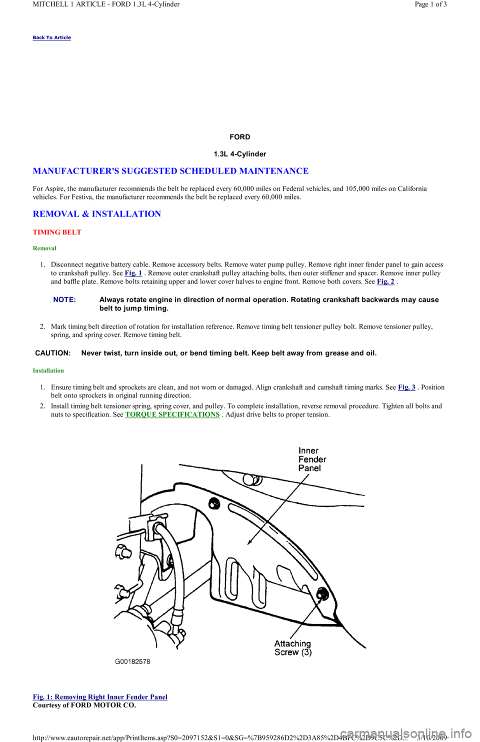
1. Disconnect negative battery cable. Remove accessory belts. Remove water pump pulley. Remove right inner fender panel to gain access
to crankshaft pulley. See Fig. 1
. Remove outer crankshaft pulley attaching bolts, then outer stiffener and spacer. Remove inner pulley
and baffle plate. Remove bolts retaining upper and lower cover halves to engine front. Remove both covers. See Fig. 2
.
2. Mark timing belt direction of rotation for installation reference. Remove timing belt tensioner pulley bolt. Remove tensioner pulley,
spring, and spring cover. Remove timing belt.
Installation
1. Ensure timing belt and sprockets are clean, and not worn or damaged. Align crankshaft and camshaft timing marks. See Fig. 3 . Position
belt onto sprockets in original running direction.
2. Install timing belt tensioner spring, spring cover, and pulley. To complete installation, reverse removal procedure. Tighten all bolts and
nuts to specification. See TORQUE SPECIFICATIONS
. Adjust drive belts to proper tension.
Fig. 1: Removing Right Inner Fender Panel
Courtesy of FORD MOTOR CO. NOTE:Always rotate engine in direction of norm al operation. Rotating crankshaft backwards m ay cause
belt to jum p tim ing.
CAUT ION: Never twist, turn inside out, or bend tim ing belt. Keep belt away from grease and oil.
Page 1 of 3 MITCHELL 1 ARTICLE - FORD 1.3L 4-Cylinder
3/10/2009 http://www.eautorepair.net/app/PrintItems.asp?S0=2097152&S1=0&SG=%7B959286D2%2D3A85%2D4BFC%2D9C5C%2D
...